Titan Lifts HD2P-10000AC-D Instruction manual

INSTALLATION, OPERATION
& MAINTENANCE MANUAL
FOLLOW THIS MANUAL CAREFULLY TO ENSURE THE EQUIPMENT WILL
FUNCTION CORRECTLY AND PROVIDE MANYYEARS OF DEPENDABLE SERVICE.
FAILURE TO FOLLOW THESE INSTRUCTIONS AND SAFETYWARNINGS MAY
RESULT IN PERSONAL INJURY OR PROPERTY DAMAGE. KEEP THIS MANUAL IN A
SAFE DRY PLACE FOR FUTURE REFERENCE.
MODEL:
HD2P-10000AC-D
10,000 LB CAPACITY 2 POST DIRECT DRIVE LIFT
®

Products May Be
Upgraded Without Notice
PleaseVisit
WWW.TITANLIFTS.COM
For The Latest Version Of
This Manual
P.O. Box 7069 • Greenwood, IN 46142 • Ph. 888-908-4826 • Fx. 317-215-2770 • www.titanlifts.com

CONTENTS
1-SAFETY .....................................................................................................................1
1.1 INTRODUCTION........................................................................................................................ 1
1.2 SAFETY INSTRUCTIONS FOR COMMISSIONING...................................................................... 1
1.3 SAFETY INSTRUCTIONS FOR OPERATION............................................................................... 1
1.4 SAFETY INSTRUCTIONS FOR MAINTENANCE ......................................................................... 3
1.5 RISKS....................................................................................................................................... 3
2-DESCRIPTION............................................................................................................4
3-UNPACKING & SETUP................................................................................................5
3.1 DELIVERY AND CHECK OF PACKAGES ..................................................................................... 5
3.2 LIFTING AND HANDLING.......................................................................................................... 5
3.3 PREPARATION ......................................................................................................................... 5
4 SPECIFICATIONS .......................................................................................................6
5-FLOOR REQUIREMENTS ............................................................................................6
5.1 SELECTING THE SITE AREA ..................................................................................................... 6
5.2 FLOOR REQUIREMENTS ........................................................................................................... 6
5.3 IMPORTANT CONCRETE AND ANCHORING INFORMATION ..................................................... 7
5.4 ANCHORING TIP SHEET........................................................................................................... 7
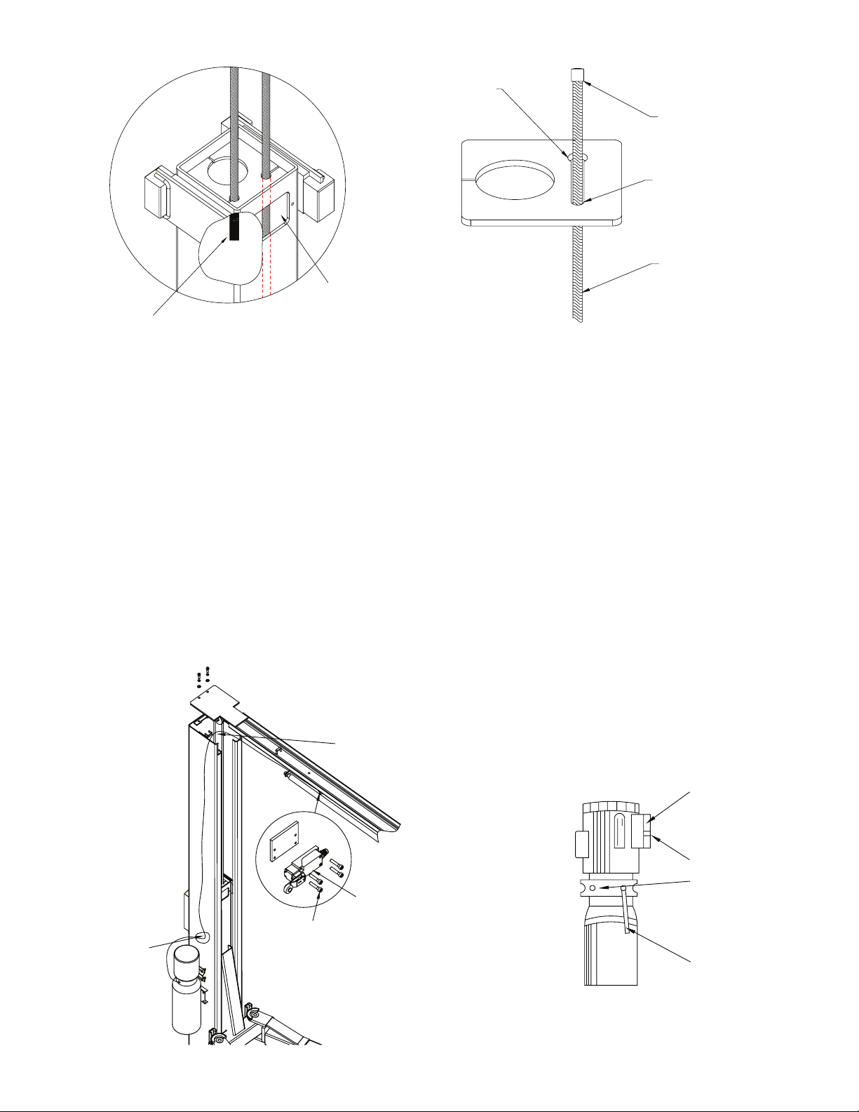
6-INSTALLATION INSTRUCTIONS................................................................................8
7-OPERATION INSTRUCTIONS...................................................................................13
7.1 DEFECTS / MALFUNCTIONS....................................................................................................13
7.2 CONTROLS..............................................................................................................................13
7.2.1 UP CONTROL.......................................................................................................................................................................... 13
7.2.2 SAFETY LOCK CONTROL...................................................................................................................................................... 13
7.2.3 LOWERING CONTROL ........................................................................................................................................................... 14
7.3 OPERATION.............................................................................................................................14
8-MAINTENANCE........................................................................................................16
8.1 MAINTENANCE SCHEDULE .....................................................................................................16
8.1.1 DAILY ....................................................................................................................................................................................... 16
8.1.2 WEEKLY ................................................................................................................................................................................... 16
8.1.3 MONTHLY................................................................................................................................................................................ 17
8.1.4 BIMONTHLY............................................................................................................................................................................ 17
8.1.5 YEARLY .................................................................................................................................................................................... 17
8.1.6 EVERY OTHER YEAR.............................................................................................................................................................. 17
8.2 MAINTENANCE BY OPERATOR ...............................................................................................18
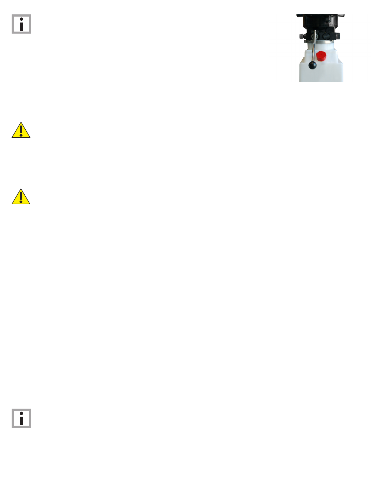
8.2.1 HYDRAULIC SYSTEM ............................................................................................................................................................ 18
8.2.2 GREASING POINTS................................................................................................................................................................ 18
8.2.3 OPERATION AND WEAR CHECKS ....................................................................................................................................... 19
8.2.4 LIFT STABILITY...................................................................................................................................................................... 19
8.3 CLEANING ...............................................................................................................................19
9-TROUBLESHOOTING ...............................................................................................20
10-OWNER/EMPLOYER RESPONSIBILITIES................................................................21
11-DIAGRAMS (FIG. 1-5).............................................................................................22
FIG. 1 - MAIN COMPONENTS........................................................................................................22
FIG. 2 - EXPLODED PARTS VIEW ...................................................................................................23
FIG. 3 - ELECTRICAL .....................................................................................................................25
FIG. 4 - POWER UNIT.....................................................................................................................26
FIG. 5 - DIMENSIONS ....................................................................................................................27

PO Box 7069 Greenwood, IN 46142
1.888.908-4826 FAX (317) 215.2770
www.titanlifts.com
TITAN MARKETING, LLC
®
To Our Valued Customers:
Thank you for purchasing a Titan Lifts®product. We hope this high quality equipment provides you with years of
dependable service.
It is unfortunate that rare situations may occur with the products you purchase from Titan Lifts®. We value your
business as well as the trust you have and need to maintain your relationship with us. Titan Lifts®carries liability
coverage that may protect our customers if a situation does occur. However, as in all accidents there must be
proof of liability for a claim to be made. Our insurance company requires the following procedures be observed in
order to consider a claim:
A. The claimant must contact the Titan Lifts®distributor immediately with the facts of the situation.
B. If any equipment is damaged, including vehicles or shop equipment, Titan Lifts®must be given the
opportunity to send an impartial representative to the site for proper assessment of the situation.
C. The Vehicle cannot be moved until either an impartial representative has reviewed the accident or clear
and precise pictures are taken that reect all the pertinent information for an impartial representative to be able
to access the information from a distance. Titan Lifts®or its representatives must approve the pictures before
anything can be moved.
D. If any potential liability is determined on behalf of Titan Lifts®, two estimates must be submitted for
damages to be reimbursed.
It is imperative that the claimant complies with these procedures, because without proper assessment of the
situation a claim will be denied.
ARBITRATION NOTICE
The installation or use of this equipment shall constitute an acknowledgement that the user agrees to resolve any
and all disputes or claims of any kind whatsoever, which relate in any way to the equipment, by way of binding
arbitration, not litigation. No suit or legal action may be led in any state or federal court. Any arbitration shall be
governed by the Federal Arbitration Act, and administered by the American Mediation Association, Indianapolis
Indiana. The maximum amount that an arbitrator may award and all damages shall not exceed the retail value of
this equipment.
WARRANTY NOTICE
This equipment must be assembled and used in the manner according to the documentation provided to be
covered by warranty.
Damaged or missing components must be reported within 72 hours of receipt to your freight carrier and to the
distributor. Claims must be led to cover cost.
If you have any questions or if we can be of any further assistance, please don’t hesitate to contact a Titan Lifts®
representative at 1-888-908-4826. Thank you for the opportunity to continue to serve your lift equipment needs.

1
1-SAFETY
INSTRUCTIONS
1.1 INTRODUCTION
• The lift may be installed and commissioned by authorized service personnel only.
• The standard lift version may not be installed and commissioned in the vicinity of
explosives or ammable liquids, outdoors or in moist rooms (e.g. car wash).
• Read this entire manual.
• Load should not exceed rated capacity for this lift –10,000 lbs. (2,500 lbs per lift arm)
• Only trained authorized personnel over the age of 18 years should operate the lift.
• Indoor use recommended.
• Always lift the vehicle using all four arms.
• Never use the lift to raise one end or one side of vehicle.
FAILURE TO COMPLY WITH INSTRUCTIONS COULD RESULT IN
PROPERTY DAMAGE.
WARNING: READ ENTIRE MANUAL AND COMPLY WITH ALL SAFETY AND SERVICE
PRECAUTIONS. DEATH, PERSONAL INJURY AND / OR PROPERTY DAMAGE MAY OCCUR IF
INSTRUCTIONS ARE NOT FOLLOWED CAREFULLY.
Personal injury and property damage incurred due to non-compliance with these safety
instructions are not covered by the product liability regulations.
FAILURE TO COMPLY WITH INSTRUCTIONS COULD RESULT IN PERSONAL
INJURY.
SYMBOLS
IMPORTANT INFORMATION
1.2 SAFETY INSTRUCTIONS FOR COMMISSIONING
1.3 SAFETY INSTRUCTIONS FOR OPERATION

2
WARNING: Prior to completely raising the vehicle, raise the vehicle 6” off the ground
and check the adapter pads for solid contact by performing the “BUMPER TEST”. Walk
around the back of the vehicle and push up and down on the bumper. The vehicle will rock,
but should not at any time lose contact with the pads. If the vehicle is bouncing off the
pads or feels at all unstable, you should lower it back to the ground and reposition the pads
to balance the load. Repeat this process until the vehicle is completely stable.
WARNING: Use this lift only in well ventilated areas. Carbon monoxide exhausted
from running vehicle engines is a colorless, odorless fume that, if inhaled, can cause
serious personal injury or death.
WARNING: People with pacemakers should consult their physician(s) before using
this product. Operation of electrical equipment in close proximity to a heart pacemaker
could cause interference or failure of the pacemaker.
WARNING: This product contains or produces a chemical known to the State of
California to cause cancer and birth defects (or other reproductive harm). (California Health
& Safety Code 25249.5 et seq.)
• Maintain a safe working environment. The work area should be clean, dry, clutter free, and
sufciently lit.
• Vehicle doors should be closed during the raising and lowering cycles.
• Closely watch the vehicle and lift during the raising and lowering cycles.
• Do not operate the lift in explosive atmospheres, such as in the presence of ammable
liquids, gases, or dust. Power equipment can create sparks which may ignite ammables.
• Keep hands, tools, and other extremities from under carriage and moving parts.
• Never operate this lift with someone on it.
• Do not allow anyone on the lift or inside a raised vehicle.
• Keep children and bystanders away from work area. Do not let children operate or play
on lift.
• Wear proper safety attire. Do not wear loose tting clothing while operating lift. Long hair,
jewelry and sleeves should be secured.
• Never leave the lift unattended while under a load.
• Do not operate this lift if under the inuence of drugs, alcohol, or medication. Operator
must be alert at all times when using heavy lift equipment.
• Comply with all applicable accident prevention regulations.
• Only use the vehicle manufacturer’s recommended lifting points.
• After positioning the vehicle, apply the parking brake.
• Use caution when removing or installing heavy vehicle components which may result in
center-of-gravity displacement.
• Use this lift only for the work it is intended. Do not use this product for an application for
which it was not designed. Misuse can lead to personal injury and/or property damage.

3
• Maintenance or repair work should be done by authorized service personnel only.
• Work on the electrical equipment should be done by certied licensed electricians only.
• Ensure that ecologically harmful substances are disposed of in accordance with the
appropriate regulations.
• To prevent the risk of damage, do not use high pressure / steam jet cleaners or caustic
cleaning agents.
• Do not replace or override the safety devices.
WARNING: Risks the personnel could encounter, due to an improper use of the lift, are
described in this section.
CRUSHING RISK
During lowering of runways and vehicles, personnel must not be within the area
covered by the lowering trajectory. The operator must be sure no one is in danger before
operating the lift. Stay clear of the lift when lowering or raising vehicles. Keep hands and
feet away from moving parts and especially points that could pinch. Keep your feet clear of
the lift when raising and lowering vehicles.
RISK OF THE VEHICLE FALLING FROM THE LIFT
Risk of the vehicle falling from the lift is increased: when the vehicle is improperly placed on
the platforms, when the vehicle’s weight or physical dimensions exceed the rated capacity
of the lift, or when there is excessive movement of the vehicle while on the lift. If vehicle
appears to begin falling, exit the area as quickly as possible to avoid injury. Always position
vehicle with the center of gravity midway between the adapters. Adding or removing
parts of a vehicle on the lift will alter the weight displacement on the lift. Therefore, use of
auxilary safety stands in the front and back of the vehicle is recommended. Never override
the manufactured lift controls. Always use height adapter pads when possible to ensure
proper contact. Only authorized personnel should be allowed in the lift area and the lift
should only be operated by authorized and trianed personnel. Adding or removing parts of a
vehicle on the lift will alter the weight displacement on the lift.
BUMPING RISK
When the lift is stopped at relatively low working height, the risk of bumping against
projecting parts increases. Always be aware of your surroundings and avoid bumping your
head or body on the lift or the vehicle.
1.4 SAFETY INSTRUCTIONS FOR MAINTENANCE
1.5 RISKS

4
2-DESCRIPTION
This lift is a 10,000 lb. capacity, surface mount clearoor, 2-Post Lift with asymmetric swing
arm setup and direct drive hydraulic system. The safety latch system is very similar to an
extension ladder. The safety latch is in contact with the rack as the lift ascends and drops
into place as the lift rises. Safety latch engages in rack in 3 1/2” increments at about 26
1/2” from the ground. The latch must be manually disengaged for the lift to descend. The
latch is released by pulling the release cable raising the latch up off the latch rack. Once
the raise button is pressed, the latch will automatically re-engage after approximately 3”of
travel. The work is done by a 3” cylinder directly, driven by a hydraulic pump capable of
providing 3,000 psi.
Please read the Safety Procedures and operation instructions in this manual before
operating the lift. Proper installation is very important. To minimize the chance of making
an error in installation, please read this manual thoroughly before beginning installation.
Check with building owner and/or architect’s building plans when applicable. The lift should
be located on a level oor with 4” 3000 psi concrete sufciently cured, for at least 30 days.
This is a vehicle lift installation / operation manual and no attempt is made or implied
herein to instruct the user in lifting methods particular to an individual application. Rather,
the contents of this manual are intended as a basis for operation and maintenance of the
unit as it stands alone or as it is intended and anticipated to be used in conjunction with
other equipment.
Proper application of the equipment described herein is limited to the parameters detailed
in the specications and the uses set forth in the descriptive passages. Any other proposed
application of this equipment should be documented and submitted in writing to the factory
for examination. The user assumes full responsibility for any equipment damage, personal
injury, or alteration of the equipment described in this manual or any subsequent damages.

5
3-UNPACKING & SETUP
Only skilled personnel who are familiar with the lift and this manual shall be allowed to
carry out, lifting, handling, transport and unpacking operations.
When the lift is delivered, carefully unpack the lift making sure all the parts have been
included. Check for possible damages due to transport and storage; verify that what is
specied in the conrmation of order is included. In case of damage in transit, the customer
must immediately inform the carrier of the problem.
Remove the lift and all parts from delivery pallet and place on a clean, solid, at surface.
Packages must be opened paying attention not to cause damage to people (keep a safe
distance when opening straps) and parts of the lift (be careful the objects do not
drop from the package when opening.)
LIFT AND HANDLE ONLY ONE PACKAGE AT A TIME
3.1 DELIVERY AND CHECK OF PACKAGES
3.2 LIFTING AND HANDLING
3.3 PREPARATION
When loading/unloading or transporting the equipment to the site, be sure to use suitable
loading (e.g. cranes, trucks) and hoisting means. Be sure to hoist and transport the
components securely so that they cannot drop, taking into consideration the package’s
size, weight, center of gravity, and its fragile parts.
Professional installation is required. The following tools and equipment are needed:
1. ISO-32, AW-32, or AW-46 hydraulic oil (2.5 Gallons)
2. Chalk line and Tape Measure
3. Rotary Hammer Drill with 3/4” Drill Bit. Core Drill Rebar Cutter recommended
4. 4’ Level
5. Sockets and Open Wrench set, metric & standard (1-1/8”for 3/4” Anchors)
6. Pliers
7. Torque Wrench
8. Metric allen wrench set

6
4 SPECIFICATIONS
5-FLOOR REQUIREMENTS
WARNING: SPECIFICATIONS OF CONCRETE MUST BE ADHERED TO. FAILURE
TO DO SO COULD CAUSE LIFT FAILURE RESULTING IN PERSONAL INJURY
OR DEATH. THE FLOOR SHOULD BE A REINFORCED CONCRETE SLAB NOT
LESS THAN 4” (101.6MM) THICKWITH THE COMPRESSIVE STRENGTH OF THE
CONCRETE NO LESS THAN 3,000 PSI.
DANGER: FOR CORRECT INSTALLATION OF THE LIFT, THE FLOOR MUST
BE FLAT AND LEVEL. CHECKWITH STRAIGHT EDGE AND LEVEL. IF A FLOOR IS
OF QUESTIONABLE SLOPE, CONSIDER A SURVEY OF THE SITE AND/OR THE
POSSIBILITY OF POURING A NEW LEVEL CONCRETE SLAB.
5.1 SELECTING THE SITE AREA
5.2 FLOOR REQUIREMENTS
1. Make sure that adequate space and height is available.
2. Check for ceiling clearance (lifting height plus vehicle height).
3. Check for clearance in front and rear of vehicle on lift.
4. Check for overhead garage door clearance.
Do not use the lift on any asphalt surface. Make sure the lift is used on a dry, oil/grease
free, at level CONCRETE surface capable of supporting the weight of the lift, the vehicle
being lifted, and any additional tools and equipment. The concrete oor surface should
have a minimum thickness of 4”. The concrete must have a minimum strength of 3,000 PSI,
and should be aged at least 30 days prior to use. Do not use the lift on concrete expansion
seams or on cracked, defective concrete.
IMPORTANT: NEW CONCRETE MUST BE ADEQUATELY CURED AT LEAST 30
DAYS MINIMUM. NO LIABILITY FOR ANY DAMAGESWILL BE ACCEPTED SHOULD
YOU INSTALL THE LIFT ON AN UNSUITABLE FLOOR.
Model Description Capacity Lifting Time Overall Height Overall Width Between Posts
HD2P-
10000AC-D
Clear Floor/
Asymmetric 10,000 lbs 75 sec. 144 3/4” 145” 117 3/8”
Drive-Thru Liting Height Power Unit
98” 72” 220V
*Due to minor variances in the manufacturing process, dimensions in this manual may vary slightly from the nished product.

7
5.3 IMPORTANT CONCRETE AND ANCHORING INFORMATION
1. Concrete shall have compression strength of at least 3,000 PSI and a minimum
thickness of 4”. Measure the length of the supplied anchor bolts in order to achieve a
minimum anchor embedment of 3-1/4”. If the top of the anchor exceeds 2” above the
oor grade, you DO NOT have enough embedment.
2. Before drilling 3/4” dia. Holes in concrete oor using holes in column base plate as
guide, make sure the hole distance from the edge is not less than 6”. Hole to hole
spacing should not be less than 6 1/2 in any direction. Concrete thickness should be a
minimum of 4”
3. DANGER: DO NOT Install on asphalt or other similar unstable surface. Columns are
supported only by anchoring in oor.
4. Shim each column base until each column is plumb. If one column has to be elevated
to match the plane of the other column, full size base shim plates should be used.
Torque anchors to 85 ft-lbs. Shim thickness MUST NOT exceed 1/2”. Adjust the column
extensions plumb.
5. If anchors do not tighten to 85 ft-lbs. installation torque, replace concrete under each
column base with a 4’ x 4’ x 6” thick 3,000 PSI minimum concrete pad keyed under and
ush with the top of existing oor. Let concrete cure at least 30 days before installing
lifts and anchors.
5.4 ANCHORING TIP SHEET
1. Use a concrete hammer drill with a carbide tip, solid drill bit the same diameter as the
anchor, 3/4”. (.775 to .787 inches diameter). Do not use excessively worn bits or bits
which have been incorrectly sharpened.
2. Keep the drill perpendicular to the concrete while drilling.
3. Let the drill do the work. Do not apply excessive pressure. Lift the drill up and down
occasionally to remove residue to reduce binding.
4. Drill the hole for anchor bolt completely through the concrete. If an error is made during
the installation of these anchors, this will allow for the anchor bolt to be driven down
into the ground, so that a new anchor may be installed in place (g.1).
5. Be sure to clean all dust from hole. (g. 2).
6. Place a at washer and hex nut over threaded end of anchor, leaving approximately 1/4
inch of thread exposed above the nut (g.3). Carefully tap anchor into the concrete until
nut and at washer are against base plate. Be sure to only tap the top of the anchor and
not the nut. This could cause damage to the threads of the anchor.
7. Tighten the nut (g. 4) to 85 ft-lbs of torque.
DO NOT USE AN IMPACT
WRENCH TO TIGHTEN
ANCHORS!

8
6-INSTALLATION INSTRUCTIONS
PLEASE READ THIS INSTRUCTION BEFORE STARTING TO OPERATE THE LIFT.
1) After unloading the lift, place it near the intended installation location.
2) Remove the shipping bands, packing materials and the power unit from the lift.
Carefully remove the parts from the column inside. Unbolt the column from the
shipping brackets.
3) Position the columns facing each other 145” (3683 mm) between outside base plates.
Square the columns by measuring from corner points on base plates (within 1/4”). (Fig.
1) NOTE: The power unit column is referred to as the main side column and the non-
power unit column is referred to as the offside column.
4) Using a 3/4” diameter concrete drill, drill the anchor holes in the main side column,
installing anchors as you go. NOTE: Remember to place washer and nut over threads,
leaving approximately 1/4” of threads exposed above the nut. Use a block of wood
or rubber mallet to drive anchor bolts in. Drill to a minimum depth of 4” to insure
maximum holding power.
5) Using a level, check column for side-to-side plumb and front-to-back plumb. If needed,
use horseshoe shims provided by placing shims underneath the base plate and around
the anchor bolt. This will prevent bending the column base plate (Shim thickness should
not exceed 1/2”). Thread the 3/4” nuts onto the anchor bolts down to the column base
plate, however do not tighten at this time. (Fig.2) NOTE: Do not use impact wrench.
Check for ceiling clearance to conrm the lift can be set up in your bay.
$
%
PP
Fig. 1 Fig. 2

9
6) Using a tape measure, measure from front corner of the base to the opposite front
corner to ensure columns are square.
7) Attach the ceiling safety bar and switch to the
overhead cross beam. (Fig. 11)
8) Install the overhead cross beam on the column
tops. (Fig. 3)
9) After overhead beam is assembled, drill and
anchor offside column as described in steps 4
and 5. Again check the plumb for both columns
carefully. Tighten all the anchor bolts to 85 ft-lbs.
of torque for each column. NOTE: Do not use
impact wrench.
10) Connect the safety release cable between the two
latches. Check that the tension of the cable is tight. Pull the single point release handle
several times and check the tension again by making sure both latches release at the
same time when the handle is pulled. (Fig. 4 & Fig. 5)
11) Mount the power unit to the mounting bracket located on the main column using the four
supplied 5/16” nuts and bolts.
12) Install the 90-degree hydraulic tting on the power unit. Connect the short hydraulic hose
to the “T” tting at the base of cylinder in the mainside column and to the power unit.
Then run the long hose through the columns and overhead cross beam. Connect the
hose to the tting on the base of each cylinder. (Fig. 6- 7 and diagram Fig. 2)
Cable for
ceiling safety
device
Safety switch
Cross beam
Fig. 3
Fig. 4 Fig. 5
Mainside Column Locking Device Offside Column Locking Device
cable wheel
cable
cable fixing nut
M6X35 bolt
latch
releasing rod
R pinspindle
spring
R pin
latch
spring
cable fixing nut
cable
cable wheel M6X35 bolt

10
13) Raise the carriages (approximately 28” from the ground)
so that they are resting on the rst safety lock position
(Fig. 8). Connect the equalizing cables as shown in the
cable diagram. NOTE: (See Fig. 9-10 and diagram Fig. 2)
A. First put one cable bolt end through the left hole in
the upper end of the carriage. Lock this end by the
nut. Let 1/2” of thread pass through the nut.
B. 2. Pull the other end of the cable up, around the
sheaves on the overhead cross beam, down to the
other carriage in the other column. Put the stud through the big hole at right corner
of the carriage. Then around the sheaves in the column bottom, then back up to
the carriage again. Make sure the cable stud goes through the big hole and move
through the small hole in the carriage from the bottom. This completes the rst
equalizing cable run.
C. Do the same for the other equalizing cable.
Fig. 6 Fig. 7
Fig. 8
hydraulic fitting
90 degree
'T' fitting on the
cylinder
90 degree hose
fitting
The hose should be routed
through the metal guides
Route hose through
metal guides inside
column
WARNING: BE SURE THE HOSEWILL NOT BE TOUCHED BY ANY MOVING
PARTS INSIDE THE COLUMNS.
WARNING: MAKE SURE THE CARRIAGES ARE SET ON THE SAFETY LOCK
POSITIONS AT THE SAME HEIGHT.
raise up the carriages
to 28" high and lock
both of them

11
Bottom End of Carriage
ATTENTION
cable stud goes through
the big hole then moves
to small end
big hole end
small hole end
cable stud
equalizing cable
adjusting
window
cable stud
Upper End of Carriage
Fig. 9
Fig. 11
Fig. 10
Fig. 12
14) Adjust the carriage cable tension. This is accomplished by tightening the lock nut under
the upper end of each carriage through the adjusting window. Tighten the nut on the
side that you wish to raise. Adjust each cable to approximately 1/2” side-to-side play.
When the cables are adjusted properly, the locks will click simultaniously as the lift is
raised.
15) Install the swing arms on the carriages using the included 4 pins (35). Adjust the lifting
arm gear locks on each swing arm. Check for proper engagement of the arm lock – the
rack on the lock should fully engaged in the gear on the arm.
connect
according
to the
instructions
safety
switch
fixing bolt
wire for
ceiling safety
device
lowering handle
outlet port
up button
small hole for
wire exit

12
16) Remove the ll cap from the power unit and ll the oil tank reservoir. To ll the oil tank
reservoir, the lift must be completely lowered. Fill the oil tank with a premium quality
ISO-32, or AW-46 Hydraulic Oil.
17) Using the cable provided connect the ceiling safety switch to power unit. Be sure that
the cable should connect to the two normal closed terminals of the switch. (Fig.11)
18) Make the Electrical hookup to the power unit: 220V Single phase. It is recommended
that a 220 Volt, 30 Amp twist lock plug be installed in the power line just ahead of the
power unit. Use wire capable of supporting a 30-amp circuit. (Fig. 12 and diagram Fig.
5)
19) Lubricate the cables, sheaves, release latch and inner
corners in the columns (Fig.13). Install the single hand
releasing latch covers (23).
20) Check again for the plumb of the columns. The
distance at the bottom and at the top position between
the columns should be equal. Check the height of the
lifting arms. The difference should be within 1”.
21) Do not place any vehicle on the lift at this time. Read
the operation instructions (pg 14-16) and cycle the lift
up and down several times to ensure safety latches
click together and all air is removed from the system. Ensure all hydraulic ttings are
tight and not leaking. To lower the lift, the safety latch releases must be manually
released. Latches will automatically reset once the lift ascends approximately 17” from
base. NOTE: If latches click out of sync, tighten the cable on the one that clicks rst.
WARNING: THE WIRING MUST COMPLY WITH LOCAL CODE. HAVE A
CERTIFIED LICENSED ELECTRICIAN MAKE THE ELECTRICAL HOOK-UP TO THE
POWER UNIT. PROTECT EACH CIRCUITWITH TIME
DELAY FUSE OR CIRCUIT BREAKER; 208V-230V
SINGLE PHASE. 50HZ/60HZ 30 AMP.
Fig. 13
lubricate the
cable and
latch
lubricate the
sheaves
lubricate the
inner corners
lubricate the
sheaves and
cables
WARNING: DO NOT PERFORM ANY MAINTENANCE OR INSTALLATION
OF ANY COMPONENTS WITHOUT FIRST ENSURING THAT ELECTRICAL POWER
HAS BEEN DISCONNECTED AT THE SOURCE OR PANEL AND CANNOT BE
REENERGIZED UNTIL ALL MAINTENANCE AND/OR INSTALLATION PROCEDURES
ARE COMPLETED.
DANGER: DO NOT RUN POWER UNIT WITHOUT FLUID. DAMAGE TO PUMP
CAN OCCUR. THE POWER UNIT MUST BE KEPT DRY. DAMAGE TO POWER UNIT
CAUSED BYWATER OR OTHER LIQUIDS SUCH AS DETERGENTS, ACID ETC., IS
NOT COVERED UNDERWARRANTY.

13
7-OPERATION INSTRUCTIONS
WARNING: LIFT OPERATION BY TRAINED AUTHORIZED PERSONNEL OVER
18YEARS ONLY. APPLY THE PARKING BRAKE AFTER POSITIONING THE VEHICLE
ON THE LIFT. DO NOT ALLOW ANYONE TO STAY IN LIFT AREA DURING RAISING
AND LOWERING CYCLES. CLOSELY WATCH THE VEHICLE AND THE LIFT DURING
RAISING AND LOWERING CYCLES. OBSERVE THE RATED LOAD CAPACITY AND
LOAD DISTRIBUTION. DO NOT ALLOW ANYONE TO CLIMB ON LIFT OR STAY
INSIDE VEHICLE. AFTER RAISING THE VEHICLE FRAME 6”, STOP AND CHECK
ADAPTERS FOR SECURE CONTACT. PERFORM BUMPER TEST. MAKE SURE THE
VEHICLE DOORS ARE CLOSED DURING RAISING AND LOWERING CYCLES.
WARNING: IN CASE OF DEFECTS OR MALFUNCTIONS SUCH AS JERKY LIFT
MOVEMENT OR DEFORMATION OF THE SUPERSTRUCTURE, SUPPORT OR LOWER
THE LIFT IMMEDIATELY. CONTACT QUALIFIED SERVICE PERSONNEL.
WARNING: PAY CLOSE ATTENTION WHEN SETTING THE LOCKS. THE LOCKS
MUST BE A LEVEL MATCH SET IN ORDER TO AVOID A VEHICLE TILT.
WARNING: ALWAYS LOCK THE LIFT BEFORE GOING UNDER THE VEHICLE.
NEVER ALLOW ANYONE TO GO UNDER THE LIFTWHEN RAISING OR LOWERING.
7.1 DEFECTS / MALFUNCTIONS
7.2 CONTROLS
7.2.1 UP CONTROL
7.2.2 SAFETY LOCK CONTROL
The safety latch mechanism will “Trip Over” as the lift raises and drop into each safety latch
stop. To lock the lift you must press the lowering handle on the power unit (Fig. 1) to relieve
the hydraulic pressure and let the safety locks engage into a level locked position.
Once the up button is actuated, the lift moves up until the button is
released or the limit stop is reached.
UP

14
1. Before driving a vehicle onto the lift make sure the lift is fully lowered. Before driving a
vehicle onto the lift, position the lift arms outward. Do not hit or run over the lifting arms,
as this could damage the vehicle and/or lift. Make sure the lift is fully lowered before
moving the vehicle over the lift. NOTE: It is recommended to swing both arms outward
pointing toward the front of the lift prior to loading a vehicle onto the 10000AC-D.
2. Drive the vehicle over the lift while keeping the vehicle parallel with the lift and aligning
the center of gravity of the vehicle with the center of the lift. NOTE: The “Center of
Gravity” (COG) of the vehicle is the balance point at which there is equal weight in front
of and behind the COG, and equal weight on both sides of the COG. The COG is not
necessarily the dimensional center of the vehicle, but is often slightly toward the engine
from the dimensional center of the vehicle.
3. Turn off the vehicle’s engine and engage the parking brake of the vehicle.
4. Read the vehicles owner’s manual to identify the recommended vehicle lifting points.
5. Prepare the work area according to this manual. Move the lifting arms inward, and
position the rubber pads to contact with the vehicle manufacturer’s recommended
lifting points.
Press the power button to raise the carriages high enough up
off the locks so that they can be disengaged. Press down on the
lock release lever located on the power unit column to manually
disengage the both locks.
WARNING: ALWAYS RELEASE BOTH SIDES.
Press the lowering handle Fig. 1 until the lift is completely lowered.
7.3 OPERATION
NOTE: IT IS NORMAL FOR AN EMPTY LIFT TO LOWER
SLOWLY - IT MAY BE NECESSARY TO ADDWEIGHT.
7.2.3 LOWERING CONTROL
Fig. 1
WARNING: FAILURE TO OPERATE THE LIFT ACCORDING TO THIS MANUAL
MAY CAUSE DAMAGE TO THE LIFT, PROPERTY DAMAGE AND/OR PERSONAL
INJURY.
IMPORTANT: PLACE THE FOUR RUBBER PADS UNDER EDGE OF VEHICLE AT
THE FOUR JACK POINTS.
6. Once the lifting arms have been positioned under the vehicle lifting points, operate the
power switch to make contact and lift the vehicle slightly. Test to make sure the vehicle
is well balanced and the contact between the rubber pads and vehicle lifting points are
secure by performing the “BUMPER TEST.” (pg. 2) Then proceed to lift the vehicle to the
desired height.

15
7. WARNING: Do not lift the vehicle if you cannot establish secure and level lifting
points. Do not use sub-standard shims or other devices in place of approved and
recommended rubber pad adapters. Never use the lift without the rubber pads in place
on each plate and in contact with the lifting points of a vehicle.
8. Press up button and raise vehicle to desired height. Do not go under vehicle until load
rests on level safety locks.
9. While lifting the vehicle a clicking sound should be noticeable which indicates the
safety mechanism is operating. If this sound is not heard, immediately cease using the
lift and call an authorized service agent.
10. When lift reaches maximum height, a limit switch will come into operation and stop the
lift. When lift has stopped, press and hold the lowering handle (Fig. 1) until load rests on
level safety locks.
11. Once the repair work to the vehicle is complete, make sure to remove all tools, safety
jack stands, and materials from under the vehicle and lift. Also, make sure the work area
is clear and it is safe to lower the vehicle.
12. Lower vehicle by pressing the Up button to disengage the safety locks. Pull both latch
releases to release (Fig. 2) the safety locks then press the lowering handle (Fig. 1) until
the lift is completely lowered.
13. Move the lifting arms outward, out of the path of the vehicle. Clear all bystanders, and
any objects from work area and direction of vehicle.
14. Disengage the vehicle parking brake. Start the vehicle’s engine, and drive the vehicle off
the lift slowly and carefully.
WARNING: THE OPERATOR MUST BE TRAINED AND AUTHORIZED TO
OPERATE THE LIFT.
WARNING: DO NOT GO UNDER VEHICLE UNDER ANY CIRCUMSTANCES
WHILEVEHICLE IS BEING RAISED OR LOWERED.
WARNING: LOAD MUST BE EVENLY DISTRIBUTED BETWEEN BOTH LIFTING
PLATFORMS. IF LOAD IS UNBALANCED, REPOSITION VEHICLE. DO NOT LOWER
ON TO LOCKS AT DIFFERENT HEIGHTS.

16
8-MAINTENANCE
WARNING: DISCONNECT THE POWER BEFORE SERVICING THE LIFT.
IMPORTANT: THE MAINTENANCE INTERVALS INDICATED BELOW APPLY TO
AVERAGEWORKSHOP USE. THE LIFT SHOULD BE INSPECTED MORE FREQUENTLY
FOR SEVERE USE APPLICATIONS.
It is important to keep the lift clean, dry, and well maintained by establishing a periodic
preventive maintenance program to ensure trouble-free operation and long service life.
1. Check safety locking mechanism is functioning correctly.
2. Check safety lock audibly and visually while in operation.
3. Check safety latches for free movement and full engagement with rack.
4. Inspect the condition of rubber lifting pads and replace as necessary if worn or torn.
5. Check hydraulic connections, and hoses for leakage.
6. Check chain connections - Bends, cracks - and looseness.
7. Check for frayed cables in both raised and lowered positions.
8. Check snap rings at all rollers and sheaves.
9. Check bolts, nuts, and screws and tighten.
10. Check wiring & switches for damage.
11. Keep base plate free of dirt, grease or any other corrosive substances.
12. Check oor for stress cracks near anchor bolts.
13. Check swing arm restraints.
1. Check anchor bolts torque to 85 ft-lbs for the 3/4’’ anchor bolts.
NOTE: DO NOT USE IMPACT WRENCH.
2. Check oor for stress cracks near anchor bolts.
3. Check hydraulic oil level.
4. Check and tighten bolts and nuts, and screws.
5. Check cylinder pulley assembly for free movement or excessive wear on cylinder yoke or
pulley pin.
6. Check cable pulley for free movement and excessive wear.
8.1 MAINTENANCE SCHEDULE
8.1.1 DAILY
8.1.2WEEKLY
Table of contents
Other Titan Lifts Lifting System manuals

Titan Lifts
Titan Lifts HD2P-15000C Instruction manual

Titan Lifts
Titan Lifts MD-1250-XL Instruction manual

Titan Lifts
Titan Lifts MASTER HD2P-9KMSC Instruction manual

Titan Lifts
Titan Lifts HD2P-9KCL Instruction manual

Titan Lifts
Titan Lifts PREMIER HD2P-9KFP Instruction manual

Titan Lifts
Titan Lifts HD2P-9000AF Instruction manual

Titan Lifts
Titan Lifts MLJ-1000B Instruction manual

Titan Lifts
Titan Lifts RJ-6K-HP Instruction manual

Titan Lifts
Titan Lifts HD2P-12000F Instruction manual

Titan Lifts
Titan Lifts PREMIER Series Instruction manual