FLAIM Systems Trainer User manual

June 2020
FLAIM
Trainer™
User Manual
flaimsystems.com
info@flaimsystems.com
Copyright © 2020

Contents
1. Overview 1
2. What’s in the Box 3
3. Quick Start Guide 13
3.1 Hardware Setup 13
3.2 Tracking Hardware 13
3.3 Instructor Viewing Hardware 15
3.4 The SCBA Set 16
3.5 Hose Reel 17
3.6 The Nozzle 17
3.7 Half Facemask 18
3.8 Heat Suit 18
4. Turning the System On 19
5. Turning the System Off 22
6. Using the Instructor Tablet 23
6.1 Starting the Application 23
6.2 Setup Tab 24
6.3 Room Setup 24
7. Running a Scenario 27
7.1 Select Training Mode 27
7.2 Select Simulations Tab 28
8. After Action Review 30
9. Fault Finding 31
10. Battery Charging 34
10.1 Main battery charging 34
10.2 Tracker battery charging 34
10.3 Nozzle battery replacement 35
10.4 Nozzle Puck charging 35
10.5 iPad Charging 35
Contents

11. Safety 36
11.1 Travelling with Batteries 37
11.2 Charging Batteries 37
11.3 Weight 37
11.4 Reel/Hose line Forces 37
11.5 Heat 37
12. Maintenance 38
12.1 SCBA mask 38
12.2 Batteries 38
12.3 SCBA 38
12.4 Head Mounted Display (HMD) 38
12.5 Heat Suit 38
13. Travel Advice and Warnings 39
14. FLAIM Trainer Duo Setup 40
15. Adding New/Replacement Hardware 41
15.1 Connect hardware 41
15.2 Re-pairing the tracking puck 41
16. Further Support 42
Contents

Figure 1: The FLAIM Trainer system 3
Figure 2: Standard packaging for the FLAIM Trainer system 3
Figure 3: Standard packaging of support components 4
Figure 4: Standard packaging of the SCBA, VR headset and half facemask 5
Figure 5: Standard packaging of the hose reel 6
Figure 6: Tracking system 13
Figure 7: Tracking system showing plug locations 13
Figure 8: Typical configuration of training area 14
Figure 9: Trackers installed on tripods angled at ~30 degrees 14
Figure 10: Instructor viewing hardware 15
Figure 11: SCBA Main battery installation 16
Figure 12: Battery connected and secured 16
Figure 13: Connect the hose reel to a standard power socket 17
Figure 14: Hose rewind and system power 17
Figure 15: Nozzle face showing batteries installed and tracking puck 17
Figure 16: When installed, the puck should look like this 18
Figure 17: Step 1. Power to hose reel 19
Figure 18: Step 1 Connect two trackers 20
Figure 19: Step 3. Ensure HDMI receiver is powered 20
Figure 20: Step 4. Power on SCBA Backpack - short press 20
Figure 21: Step 5. Short press to power on nozzle puck 21
Figure 22: Step 6. Power on or wake instructor tablet 21
Figure 23: Instructor tablet home screen 23
Figure 24: FLAIM Trainer instructor software 23
Figure 25: Basic room setup configuration 24
Figure 26: Room Setup Step 1 25
Figure 27: Room Setup Step 2 25
Figure 28: Room Setup Step 3 25
Figure 29: Room Setup Step 25
Figure 30: Room Setup Step 5 25
Figure 31: Room Setup Step 6 26
Contents

Figure 32: Room Setup Step 7 26
Figure 33: Room Setup Step 8 26
Figure 34: Scenario Tab 27
Figure 35: Select Training Mode Button 27
Figure 36: Select Simulation Scenario Button 28
Figure 37: Select Teleport Mode and Select Heat Vest Mode Buttons 28
Figure 38: Select Pump Pressure Button 28
Figure 39: Analysis Tab 29
Figure 40: After Action Review 30
Figure 41: Main battery charger connection 34
Figure 42: Tracker batteries connect to charger 34
Figure 43: Nozzle batteries behind tracking puck 35
Figure 44: Nozzle puck charging via micro USB cable 35
Figure 45: FLAIM Trainer Dual remote control for switching video sources 40
Figure 46: SteamVR Software 41
Figure 47: Looking for Tracking Puck and Paired! 41
Contents

Welcome to the FLAIM
community. Thank you
for your purchase of the
FLAIM Trainer™ virtual
reality training system.
1. Overview
This manual should get you on your way in no time. It is designed for trainers with
minimal understanding of virtual reality. The FLAIM Trainer system is not designed
to replace hot fire training, but instead allows experiential learning through a number
of practical scenarios developed to improve dynamic thinking, risk assessment, radio
messaging, muscle memory, hose handling technique and nozzle control. Our system
is designed so you can train people at all levels in your organisation from novice
through to experienced firefighters. Giving you the ability to train and develop their
skillset in a safe environment with immersive, repeatable and realistic fire scenarios.
The FLAIM Trainer can also be used to train the public in the dangers of fire and allow
them to appreciate the work that you do.
1

The FLAIM Systems Team
Train more, learn more, prepare better.
FLAIM Trainer provides firefighters the capacity to train situations and scenarios that
are:
• inherently unsafe and difficult to reproduce;
• no longer possible due to environmental, community and regulatory constraints;
• incur significant training cost in time, people and assets.
FLAIM Trainer places firefighters in the most realistic training scenario available by
utilising several customised elements:
• Head Mounted Display: Breathing apparatus (SCBA) kit incorporates a head
mounted virtual reality (VR) display.
• Nozzle: Hose-line system provides realistic jet or nozzle reaction force.
• Heat Suit: Heat Suit with heat generation components.
Once again, thank you for your support.
2
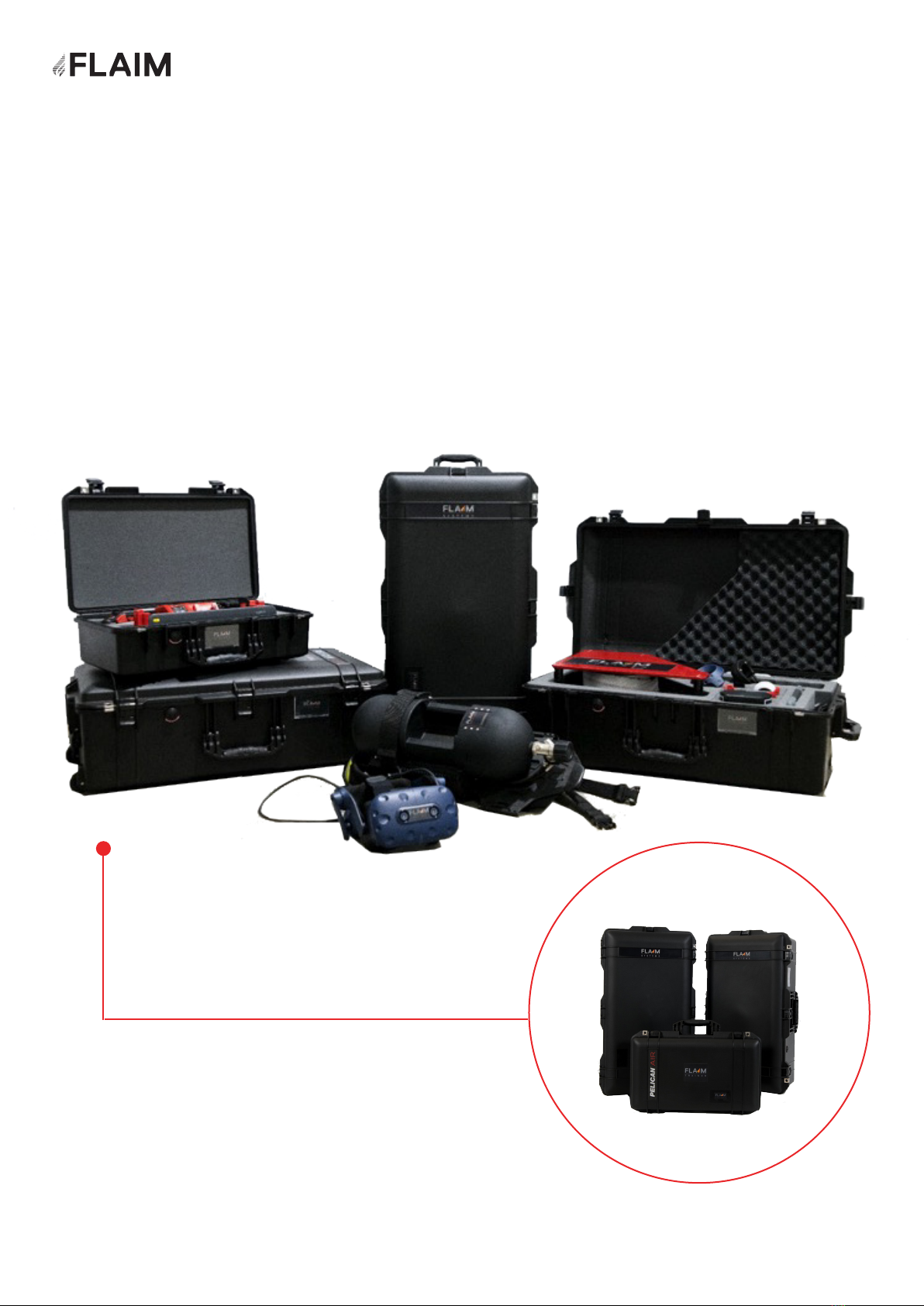
2. What’s in the box?
This section covers the FLAIM Trainer system and what to expect when you open the
box. It also lists the individual parts included and explains what they do.
Figure 1: The FLAIM Trainer system
Figure 2: Standard packaging for the
FLAIM Trainer system
3

Figure 3: Standard packaging of support components
iPad - SCBA Battery
charger underneath
Charging leads
Hose Reel
Power cable
Nozzle
Tracking Puck
Tracker batteries
SCBA Batteries
USB charger and
country specific
adaptors
4

Figure 4: Standard packaging of the SCBA, VR headset and half facemask
Tripods
VR Headset
SCBA
5

Figure 5: Standard packaging of the hose reel
Hose Reel
Nozzle/Branch
Keyboard
Hose Reel
power supply
VIVE controller
Mouse
2x VIVE tracking
hardware
2x Tracker battery
power supply
HDMI receiver
6

QTY Description Picture
1SCBA including main computer
and VR Headset
1Heat Suit
2Tripod for mounting tracking
hardware
1Force feedback Hose Reel
1TFT G-Force Nozzle/Branch
7

QTY Description Picture
1Half face SCBA mask and lung
demand valve
1Instructor iPad
2VIVE tracking hardware
1VIVE Tracking - Puck
2Standard power cable for powering
tracking hardware from battery bank
8

QTY Description Picture
1iPad charging cable
1USB cable for nozzle tracking puck
charging
2Swivel mount for VIVE tracking hardware
installation
2Tracker batteries
2Tracker Battery – power source
9

QTY Description Picture
2Tracker Battery Adapters – brackets for
power source
1HDMI receiver
2Main SCBA batteries
1Mouse for user setup – initial
*Mouse may appear different to image
shown
1VIVE controller (for future AR
instructor use)
10

QTY Description Picture
1USB Rapid travel charger (country specific)
for charging VIVE controller, puck and iPad.
1Milwaukee battery charger for both
tracker batteries and main SCBA battery
charging (country specific power plug
supplied)
1Instructor and upgrade keyboard (not
used in general operation)
1Hose Reel Power Supply
2VIVE Tracker room mounting hardware
11

QTY Description Picture
1Country specific Hose Reel power cable
1USB VIVE controller and HDMI Receiver
power cable
1HDMI extension cable
12
3. Quick Start Guide
3.1 Hardware Setup
3.2 Tracking hardware
This section covers the basic setup, use and
running of the FLAIM Trainer system.
The hardware consists of a number of support
components that must be installed before training
can commence. This section covers the placement
and installation of all tracking hardware and
instructor television (or projector) monitoring
equipment.
Tracking is achieved using the VIVE lighthouse
system from HTC. A pair of trackers are installed
that define the maximum training space allowable
for the user to train in. At present the system
supports a training area of 6 x 6m ~(20 x 20ft)
or a total distance between the two trackers not
greater than about 7m (23ft).
This training area should be cleared of all furniture,
not contain large mirrors or highly reflective
surfaces and should not be in direct sunlight. The
tracking system used by FLAIM Trainer relies on
Infrared Light (IR) and tracking performance can be
degraded in certain conditions.
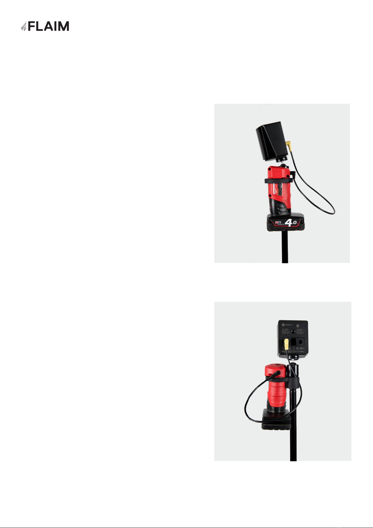
Each tracker is assembled as per the following
figures.
As shown in Figure 7, the tracking system
is plugged into the power receptacle. Once
assembled, the system can be placed into position
at diagonal corners of the training space and
powered on (by connecting the battery to the
system).
Figure 6: Tracking System
Figure 7: Tracking system showing plug
locations
13

Please ensure that there is at least one red light
(out of a possible 4) on the power adaptor before
beginning a scenario.
The trackers should be placed at diagonal
corners of the training space at a height of ~2m
(6ft). The sensor face should be angled down at
an approximately 30-degree angle as shown in
Figure 9.
When installed and powered on, both trackers
should show a power led on the front window.
Note
Figure 8: Typical configuration of training area Figure 9: Trackers installed on tripods angled at ~30
degrees
14
3.3 Instructor viewing hardware
In addition to the tracking hardware, the instructor viewing hardware must also be
installed. This hardware receives the signal transmitted by the FLAIM Trainer SCBA
so that the instructor and/or fellow trainees can view live footage from the training
environment. This hardware is crucial for first time setup of the tracking environment.
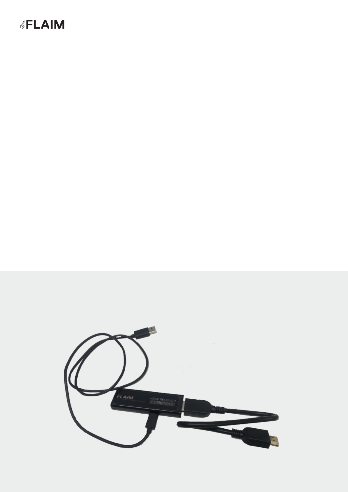
The instructor viewing hardware consists of a HDMI receiver that connects to a
television/projector (not supplied) via a supplied HDMI cable (Figure 10).
Power is supplied to the HDMI receiver from the included USB Power supply or by
plugging the attached micro USB lead into the USB port on most newer televisions and
projectors.
The system is a commercial unit and has been trialled with a number of televisions
and projectors with great success. Some systems cannot supply enough power from
their in-built USB port and it is suggested to use the included power supply in this
instance.
When powered, the receiver power light will glow blue.
Figure 10: Instructor viewing hardware
15
Other manuals for Trainer
1
Table of contents
Other FLAIM Systems Safety Equipment manuals


Popular Safety Equipment manuals by other brands


SKYLOTEC
SKYLOTEC ERGOGRIP SK 12 Instructions for use

Pizzato Elettrica
Pizzato Elettrica CS DM-01 Series quick start guide

BFT
BFT ERIS A30 installation manual

Dräger
Dräger PARAT C Series Instructions for use

ROCK EXOTICA
ROCK EXOTICA Soloist instruction manual

AAT Holding
AAT Holding KaDe KDH-EXIT1030-P installation manual


