flakt woods ECONOVENT - PUM Release Note
ECONOVENT®– PUM
Rotary heat exchanger
Technical Handbook

Fläkt Woods 3099 US 03.02 2 Specifications are subject to alteration without notice
PUMA (A–F) Rotary heat exchanger TECHNICAL HANDBOOK
CONTENTS
Design . . . . . . . . . . . . . . . . . . . . . . . . . . . . . . . . . . . . . . . . . . . . . . . . 3,4
Design – Description – Accessories . . . . . . . . . . . . . . . . . . .5,6
The process in the psychrometric chart . . . . . . . . . . . . .7,8,9
Rotor selection . . . . . . . . . . . . . . . . . . . . . . . . . . . . . . . . . . . . . . . .10
Selection of heat exchanger type and size . . . . . . . . . . . . .11
Efficiency . . . . . . . . . . . . . . . . . . . . . . . . . . . . . . . . . . . . . . . . . . . . .12
Design chart . . . . . . . . . . . . . . . . . . . . . . . . . . . . . . . . . . . . . . . . . .13
Project design advice . . . . . . . . . . . . . . . . . . . . . . . .14,15,16,17
Control Systems . . . . . . . . . . . . . . . . . . . . . . . . . . . . . . . . .17,18,19
Installation . . . . . . . . . . . . . . . . . . . . . . . . . . . . . . . . . . . . . . . . .20,21
Dimensions and weights . . . . . . . . . . . . . . . . . . . . . . . . . . .22,23
Ordering key . . . . . . . . . . . . . . . . . . . . . . . . . . . . . . . . . . . . . . .24,25
Sample specification . . . . . . . . . . . . . . . . . . . . . . . . . . . . . . . .26,27

Fläkt Woods 3099 US 03.02 3 Specifications are subject to alteration without notice
PUMA (A–F) Rotary heat exchanger TECHNICAL HANDBOOK
Design
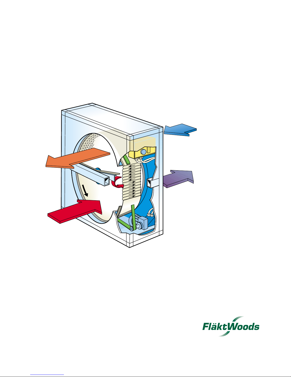
The ECONOVENT unit is a regenerative heat
exchanger comprising a rotor which transfers heat and
moisture from the exhaust air to the supply air as it
rotates.
The supply air flows through one half of the heat
exchanger, and the exhaust air flows in counterflow
through the other half. Supply air and exhaust air thus
flow alternately through small passages in the rotor in
opposite directions.
Most important benefits:
Reduced heat demand which, in turn, reduces the size
and thus also the investment cost for the boiler station
or the connection charge for tariff-linked heat, such as
electric power and heat from the district heating system.
In addition, the sizes and thus the investment costs for
air heaters, pipes and pumps are reduced.
Reduced heat energy demand, which reduces the
operating costs, i.e. the oil consumption or the con-
umption charge for electrical energy or heat from the
district heating system.
Reduced energy consumption for humidification
(hygroscopic rotors) of the air, since moisture is also
recovered.
Reduced cooling power demand (hygroscopic rotors)
which reduces the size and thus also the investment
cost for the refrigeration system (compressor, cooling
tower, etc.), air coolers, pumps and pipes.
Reduced energy consumption for refrigeration
(hygroscopic rotors).
General reduction in environmental pollutants.
ECONOVENT is a complete product range of rotary
heat exchangers for air handling systems in various types
of environments and plants. ECONOVENT is available
with six different materials for the rotor, and the right
material can therefore always be specified to suit most
environments.
2000 3000 4000 5000 10000 20000 30000 50000
Air flow, m3/h
Air flow, m3/s
100000 150000
0.4 0.5 1 2 3 4 5 10 20 30 40 500.30.2
Air flow, CFM
500 1000 2000 3000 4000 5000 10 000 20 000 30 000 50 000 100 000
060
080
095
110
135
150
170
190
200
215
240
265
290
320
350
380
420
460
500
120
Size
Air velocity 400 FTM
Air velocity 900 FTM
FPM
FPM
Fläkt Woods 3099 US 03.02 4 Specifications are subject to alteration without notice
PUMA (A–F) Rotary heat exchanger TECHNICAL HANDBOOK
Design
General
The heat exchanger consists of a casing, a rotor of hygro-
scopic or non-hygroscopic type, and a rotor drive unit.
Adjustable seals are fitted between the casing and the
rotor on both sides, in order to minimize the leakage of
air. The heat exchanger can be ordered either with or
without purging sector.
The purging sector is adjustable and prevents the carry-
over of exhaust air to the supply air.
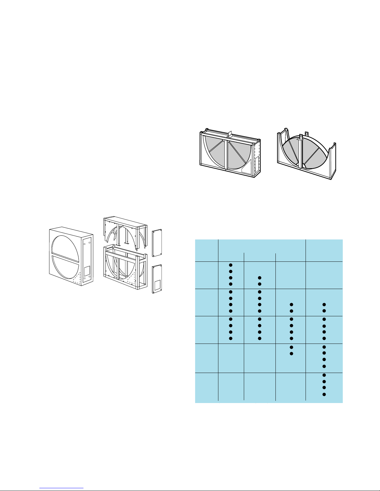
Casing for sizes 060–240
The casing is of single-skin design and is made as one
unit. An inspection panel (2 panels for size 190 and larg-
er sizes) is located on the end wall or front (optional) of
the casing as shown in Fig. 1. The drive motor and speed
controller (for a variable speed unit) are fitted and tested
at the factory. Note that a split casing as shown in Fig. 2
is available for size 150 and larger sizes.
Casing for sizes 265–500
The casing is of single-skin design and is delivered split,
as shown in Fig. 3. Size 265 and 290 units can also be
ordered assembled at the factory. Inspection panels are
located on the front or on the end wall (optional) of the
heat exchanger as shown in Fig. 3. The drive motor is
installed on the inside of the inspection panel. Access
panels are provided on the front of the casing for installa-
tion of the rotor sector.
Fig. 1 Fig. 2
Inspection panel
standard
Inspection panel, optional
Inspection panel
standard
Inspection panel, optional
Fig. 3.
Delivery
The ECONOVENT PUM(A-F) Heat exchanger is deliv-
ered as shown in Table 1.
●Standard. 1) A composite rotor (PUMF) is always sectorized.
One factory-assembled unit Split casing
Split casing ( 2 units)
Size One-piece Sectorized Sectorized Sectorized
bbb rotor 1) rotor rotor rotor
060
080
095 ●
110
120 ●
135
150
170
190
200
215
240 ●
265
290
320
350
380
420
460
500
Delivery form in split version.

Fläkt Woods 3099 US 03.02 5 Specifications are subject to alteration without notice
PUMA (A–F) Rotary heat exchanger TECHNICAL HANDBOOK
Design - Description - Accessories
Drive system
The drive system consists of an electric motor (constant
speed or variable speed) with reduction gear, driving the
rotor by means of a jointed V-belt. The V-belt is kept
automatically tensioned by the spring-mounted motor
bracket.
Temperature limit
The heat exchanger is suitable for use at temperatures up
to +165°F.
The temperature in the motor compartment must not
exceed +100°F. If the supply or exhaust air temperature
exceeds +100°F, see further under Temperature limit on
page 19.
Materials and finish
Frame Sizes 060–240: galvanized sheet metal
Sizes 265–500: rotor support steel beams
primed with anti-corrosion
paint.
Cover panels, inspection panels and purging sector: gal-
vanized sheet metal.
Hub (one-piece rotor): aluminum
Hub (sectorized rotor): steel, primed with anti-
corrosion paint.
Rotor material
ALUMINUM ROTORS (A, C and E rotors) are non-
hygroscopic, i.e. they recover only sensible heat, as long
as condensation does not occur.
ALUMINUM ROTORS (B and D rotors) are hygro-
scopic and recover both sensible heat and latent heat
(on changing moisture content).
COMPOSITE ROTORS (F) rotors are hygroscopic, i.e.
they recover both sensible heat and latent heat. The com-
posite material is incombustible and contains no metals,
which means that the material cannot corrode.
The material is treated with silica gel-based substances.
GENERAL SURVEY OF ROTORS
ECONOVENT Material Property Max temperature -
rotor designation range, °F
A Aluminum Non-hygroscopic 165
B Aluminum Hygroscopic 165
CEdge-reinforced aluminum Non-hygroscopic 165
DEdge-reinforced aluminum Hygroscopic 165
EEpoxy-coated aluminum Non-hygroscopic 165
FComposite Hygroscopic 165 1)
Heating and cooling energy recovery in air handling systems
- without moisture transfer.
Heating and cooling energy recovery in air handling systems
- with moisture transfer.
Heating and cooling energy recovery in air handling systems
- without moisture transfer in a corrosive environment.
Heating and cooling energy recovery in air handling systems
- with moisture transfer in a corrosive environment.
Heating and cooling energy recovery in air handling systems
- without moisture transfer in corrosive environment.
Heating and cooling energy recovery in air handling systems
- with moisture transfer in corrosive, city, marine and
coastal environments.
Application
1) Available for a max. temp. of 275°F. Get in touch with Munters International Inc.

Fläkt Woods 3099 US 03.02 6 Specifications are subject to alteration without notice
PUMA (A–F) Rotary heat exchanger TECHNICAL HANDBOOK
Design - Description - Accessories
Accessories
PUMZ-17 Duct connection frames
Slip joint connection, made of galvanized sheet metal and
fitted to the heat exchanger at the factory.
PUMZ-20 Speed detector
Used for continuous monitoring of the rotor speed, with
automatic alarm if the rotor should stop when heat recov-
ery is needed.
An alarm relay and sensor unit are needed for a constant-
speed exchanger. Only the sensor unit is needed for a
variable-speed exchanger.
PUMZ-21 Differential thermostat
In cooling energy recovery, used for switching the heat
exchanger to maximum speed when the outdoor temper-
ature is higher than the exhaust air temperature. Two sen-
sors are included for fitting in the outdoor air and
exhaust air ducts upstream of the heat exchanger.
PUMZ-27 Cleaning equipment
For automatic purging of the air passages in the rotor.
With compressed air nozzle which is moved by means of
a pneumatically actuated cylinder in a radial direction
along the face of the rotor. Nozzle, cylinder and control
unit are included.
For assistance in selecting the variant and locating the
equipment, please get in touch with Munters
International Inc. representative.
PUMZ-28 Condensate tray
For collecting and disposal of the condensate from the
rotor.

Fläkt Woods 3099 US 03.02 7 Specifications are subject to alteration without notice
PUMA (A–F) Rotary heat exchanger TECHNICAL HANDBOOK
The process in the psychrometric chart
35
70
105
140
175
-20 -10 0 10 20 30 40 50 60 70 80 90 Dry Bulb Temperature°F
Humidity Ratio
grains/lb
100 110 120
0
5
10
15
20
25
30
35
40
45
50
20%
40%
60%
12.0 12.5 14.5
14.0
13.513.0
80%
Chart 1
Non-hygroscopic rotors - type A, C and E
In type A, C and E NON-HYGROSCOPIC rotors, only
sensible heat exchange takes place as long as there is no
condensation in the rotor. As soon as condensation
occurs, the condensate will evaporate in the supply air.
The graphic presentation of the process in the psychro-
metric chart when condensation takes place varies with
the operating conditions and can therefore not be speci-
fied generally.
Outdoor air summer
Exhaust air summer
Exhaust air winter
Outdoor air winter

Fläkt Woods 3099 US 03.02 8 Specifications are subject to alteration without notice
PUMA (A–F) Rotary heat exchanger TECHNICAL HANDBOOK
The Process in the psychrometric chart
35
70
105
140
175
-20 -10 0 10 20 30 40 50 60 70 80 90 Dry Bulb Temperature°F
Humidity Ratio
grains/lb
100 110 120
0
5
10
15
20
25
30
35
40
45
50
20%
40%
60%
12.0 12.5 14.5
14.0
13.513.0
80%
Chart 2
Hygroscopic rotors - type B, D and F
In type B, D and F HYGROSCOPIC ROTORS, the
moisture and temperature efficiencies at full speed are
equal. As a result, the process in the psychrometric chart
runs along the interconnecting line between the inlet
conditions for the supply and exhaust air
Outdoor air summer
Exhaust air summer
Exhaust air winter
Outdoor air winter

Fläkt Woods 3099 US 03.02 9 Specifications are subject to alteration without notice
PUMA (A–F) Rotary heat exchanger TECHNICAL HANDBOOK
The Process in the psychrometric chart
Summer operation
Charts 1 and 2 show summer conditions in which the out-
door air is warmer and more humid than the exhaust air.
The hygroscopic rotor (Chart 2) lowers both the moisture
content and the temperature to the vicinity of the exhaust
air conditions, and gives an enthalpy efficiency of 75%. The
nonhygroscopic exchanger (Chart 1) lowers the temperature
by the same amount, but does not change the moisture con-
tent. In this case the supply air enthalpy efficiency will be
only about 25%. The example illustrates the significance of
the high moisture efficiency of the hygroscopic rotor, above
all in humid, warm climates.
Winter operation
Charts 1 and 2 show a winter case with moderately low
outdoor temperatures. No condensation takes place in the
nonhygroscopic rotor, (Chart 1) which therefore does not
contribute to the moisture content of the supply air. On
the other hand, the hygroscopic rotor (Chart 2) raises the
moisture content of the supply air by almost 11 Gr/lb of
air, which usually offers welcome humidification of the
supply air. The nonhygroscopic rotor can operate without
risk of freezing even when condensation takes place at
temperatures below 32°F.
Frosting - Defrosting
Rotor temperatures below 32°F need not necessarily cause
frosting in the rotor. Moisture transfer then takes place by
the moisture, which has been deposited as frost on the
rotor surface, being evaporated on the supply air side. For
frosting to occur, there must also be excess water in the
rotor. This will take place if the supply air is not capable
of absorbing the moisture that has condensed out of the
exhaust air.
The frosting process, which causes an increase in pressure
drop across the rotor, normally takes many hours. The
frosting problem is therefore often relieved by the out-
door temperature varying over a 24 hour period, or
because the heat exchanger is in operation during only
part of the 24-hour period.
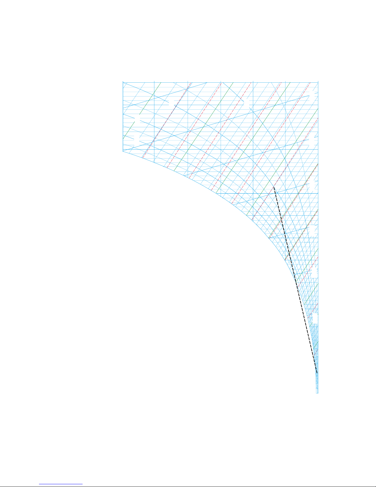
Frosting limit
Frosting will occur if excess water should occur, at the
same time as the supply air inlet temperature is below
14ºF. This temperature applies with relatively good accu-
racy at different airflow rates, full speed and typical
exhaust air temperatures occurring in comfort ventilation
systems.
Excess water will occur in the hygroscopic rotor as soon
as the interconnecting line between the inlet conditions
for the two air streams intersects the saturation line in the
psychometric chart (see Chart 3).
In the case of a nonhygroscopic rotor, excess water will
form when the interconnecting line between the supply
air condition and the exhaust air dewpoint plus approxi-
mately 7ºF, as shown in Chart 4, intersects the saturation
line in the psychometric chart.
Frosting time
As an example, it will take about 8 hours for the pressure
drop to increase by 50% if the saturation curve is inter-
sected as shown in Chart 3, and about 4 hours if the sat-
uration curve is intersected as shown in Chart 4.
Note that the frosting time will be as above if the temper-
ature and moisture conditions are constant throughout
the frosting time. But since the temperature often varies,
the frosting time may be appreciably longer. As a result of
factors such as operating time and supply air temperature
variations, experience shows that a minor intersection of
the saturation curve is permissible without significant
frosting occurring, even if the design outdoor tempera-
ture is below 14°F.
Defrosting - avoidance of frosting
Frosting can be totally avoided by preheating the outdoor
air to a temperature so that the line connecting indoor
and outdoor conditions in the psychometric chart falls
below the saturation line. Heating to 14ºF is normally
adequate. The rotor can be defrosted, normally within
5–10 minutes, in several ways.
– By reducing the rotor speed to around 0.5 r/min (see
example 5 page 22).
– By preheating the incoming outdoor air to around
23°F.
– By bypassing a sufficient amount of supply air across
the rotor so that the outlet temperature on the
exhaust air side will be at least around 41°F. As an
example, the supply air flow rate would have to be
reduced to around half for defrosting to take place at
the normal exhaust air temperature, at a 75%
temperature efficiency and an outdoor temperature
of about –4°F.
All three methods can be used for a variable speed rotor
drive, while the last two can be used with constant speed
drive.around half for defrosting to take place at the nor-
mal exhaust air temperature, around 75% temperature
efficiency and an outdoor temperature of about –4°F.
All three methods can be used for a variable-speed rotor,
while the last two can be used at constant speed.
Fläkt Woods 3099 US 03.02 10 Specifications are subject to alteration without notice
PUMA (A–F) Rotary heat exchanger TECHNICAL HANDBOOK
The process in the psychrometric chart
35
70
105
140
175
-20 -10 0 10 20 30 40 50 60 70 80 90 Dry Bulb Temperature°F
Humidity Ratio
grains/lb
100 110 120
0
5
10
15
20
25
30
35
40
45
50
20%
40%
60%
12.0 12.5 14.5
14.0
13.513.0
80%
Chart 3
Frosting in a hygroscopic rotor

Fläkt Woods 3099 US 03.02 11 Specifications are subject to alteration without notice
PUMA (A–F) Rotary heat exchanger TECHNICAL HANDBOOK
The process in the psychrometric chart
35
70
105
140
175
-20 -10 0 10 20 30 40 50 60 70 80 90 Dry Bulb Temperature°F
Humidity Ratio
grains/lb
100 110 120
0
5
10
15
20
25
30
35
40
45
50
20%
40%
60%
12.0 12.5 14.5
14.0
13.513.0
80%
Chart 4
Frosting in a non-hygroscopic rotor

Fläkt Woods 3099 US 03.02 12 Specifications are subject to alteration without notice
PUMA (A–F) Rotary heat exchanger TECHNICAL HANDBOOK
Rotor selection
Selection of the rotor material to suit the application.
Take great care to select the right material for every envi-
ronment.
If in doubt, consult Munters International.
= Rätt val = Godkänd = Ej rekommenda
PUMA PUMB PUMC PUMD PUME PUMFRotorutförande
Rotormaterial
Användningsområde
Icke hygroskopisk
(återvinning av värme)
Hygroskopisk
(återvinning av värme + fukt)
Hav - kust
Inland
Tung industri
Lätt industri
Stad
Landsbygd
Aluminium Kantförstärkt
aluminium
Epoxibelagd
aluminium Komposit
y
Key to markings
Rotor material
Application
Non-hygroscopic
(recovery of heat)
Hygroscopic
(recovery of heat + moisture)
Marine - coastal
Inland
Heavy industry
Light industry
Urban
Rural
Rotor version
Composite
Edge-reinforced
aluminum Epoxy-coated
aluminum
Right choice = Satisfactory = Not recommended
Aluminum

Fläkt Woods 3099 US 03.02 13 Specifications are subject to alteration without notice
PUMA (A–F) Rotary heat exchanger TECHNICAL HANDBOOK
Selection of heat exchanger type and size
Selection of heat exchanger
No moisture transfer required
1.Systems intended for:
comfort air handling
exhaust air with solvents or
exhaust air with dry, granular dust.
Select the ECONOVENT with A rotor or possibly C
rotor.
2.Systems with risk of corrosion and intended for:
comfort air handling
exhaust air with corrosive solvents
exhaust air with corrosive dust.
Select the ECONOVENT with E rotor.
Moisture transfer required.
3.Systems with humidification or dehumidification of
the supply air and intended for:
comfort air handling,
light industry inland.
Select the ECONOVENT with B rotor or possibly D rotor.
4. Systems with humidification or dehumidification of
the supply air and intended for:
comfort air handling
heavy industry in a coastal environment or
corrosive urban environment.
Select the ECONOVENT with D rotor or possibly F rotor.
5. Systems with high risk of corrosion and intended for:
comfort air handling
heavy industry in a coastal environment or
corrosive urban environment
Select the ECONOVENT with F rotor
For a non-hygroscopic rotor (A, C and E rotor):
The temperature efficiency can be obtained from the de-
sign chart on page 16. At maximum speed and for equal
supply and exhaust air flow
rates
ηtt = ηtf
The procedure for calculating the temperature efficiency
at different air flow rates is given in the design chart on
page 16. If the rotor size and the supply and exhaust air
flows are given, the temperature efficiency is independent
of the conditions of the supply and exhaust air.
A non-hygroscopic rotor recovers only heat as long as
condensation does not occur in the rotor. There is no
generally applicable formula for calculating the moisture
content of the supply air downstream of the rotor when
condensation takes place. If the rotor speed is reduced,
the supply and exhaust air temperature efficiencies will
decrease. This phenomenon is used for controlling the
supply air temperature downstream of the heat exchanger.
The temperature efficiency is the same for all rotor
types at a given face velocity.
Definitions, see page 15

Fläkt Woods 3099 US 03.02 14 Specifications are subject to alteration without notice
PUMA (A–F) Rotary heat exchanger TECHNICAL HANDBOOK
14
Efficiency
For a hygroscopic rotor (B, D and F rotor):
The temperature efficiency for a given rotor size and a
given supply air flow is obtained from the design chart
on page 16. At maximum speed and for equal supply and
exhaust air flow rates: ηtt = ηtf
where
ηtt = supply air temperature efficiency and
ηtf = exhaust air temperature efficiency.
At maximum speed and at different supply and exhaust
air flow rates, the supply air efficiencies are linked, and so
are those of the exhaust air.
ηtt ≈η
xt ηtf ≈η
xf
How the temperature efficiency changes at different flow
rates is shown in the design chart on page 16.
Chart 3
Temperature and moisture efficiencies at different rotor
speeds
Temperature and moisture recovery
The temperature efficiency ht and the moisture efficiency
hx at different rotor speeds are shown in Chart 3. The
chart is valid for normal changes in condition in climate
systems and at an air velocity v = 3 m/s through the
rotor.
Definitions:
Efficiency
Supply air temperature efficiency ηtt =t2-t1
t3-t1
Supply air moisture efficiency ηxt =x2-x1
x3-x1
Supply air enthalpy efficiency ηht =h2-h1
h3-h1
Exhaust air temperature efficiency ηtf =t3-t4
t3-t1
Exhaust air moisture efficiency ηxf =x3-x4
x3-x1
Exhaust air enthalpy efficiency ηhf =h3-h4
h3-h1
t = temperature (°F)
x = water content per lb of dry air (gr)
h = enthalpy (Btu/lb)
A common feature of all hygroscopic aluminium rotors is
that when the rotor speed is reduced, the moisture effi-
ciency also drops below the temperature efficiency.
However, with the ECONOVENT F rotor of composite
material, the difference between the two efficiencies on a
drop in speed is appreciably smaller.
0 102030405060 708090
0
20
40
60
80
100
Verkningsgrad η%
100
% av max. varvtal
ηt
ηx
Hygroskopisk rotor
Kompositrotor
t4, x4, h4t3, x3, h3
t1, x1, h1t
2, x2, h2
q1Tilluft q2
q4Frånluft q3
Rum
Composite rotor
Hygroscopic rotor
% of max. speed
Efficiency η%
Room
Fig. 4
Supply air q2
Exhaust air q3

Fläkt Woods 3099 US 03.02 15 Specifications are subject to alteration without notice
PUMA (A–F) Rotary heat exchanger TECHNICAL HANDBOOK
Design chart
Hygroscopic rotor with wider
foil spacing
600 800700 1 000 1 200300
0.2
0.3
0.4
0.5
1
2
3
4
5
10
20
30
40
50
200 000
150 000
100 000
50 000
40 000
30 000
20 000
15 000
10 000
8 000
6 000
5 000
4 000
3 000
2 000
1 500
500
1 000
2 000
3 000
4 000
5 000
10 000
20 000
30 000
40 000
50 000
100 000
1 000
800
Supply air flow, m3/h
Supply air flow, m3/s
Supply air flow, CFM
0.25
0.2
0.3
0.2
0.40.35 0.5 0.6 0.7 0.8 0.9 1 1.2 1.4 1.6 1.8
0.25 0.3 0.35 0.4 0.45 0.5 0.6
0.35 0.4 0.45 0.5 0.6 0.7 0.8
0.25 0.3 0.35 0.4 0.45 0.5
0.3 0.4 0.5 0.6 0.7 0.8
Air velocity, FTM
Pressure drop, IN. WG.
Pressure drop, IN. WG.
Pressure drop, IN. WG.
Pressure drop, IN. WG.
400 500
600 800700 1 000 1 200300 400 500
Pressure drop, IN. WG.
100
90
80
70
60
50
40
0.5
0.6
0.7
0.8
0.9
1.0
1.1
1.2
1.3
1.4
1.5
1.6
1.8
2.0
Air velocity, FTM
ηt= Supply air temperature efficiency, %
at maximum rotor speed
80
70
60
50
40
Composite rotor
Selected size
Non-hygroscopic rotor with
standard foil spacing
Non-hygroscopic rotor with
wider foil spacing
Hygroscopic rotor with stan-
dard foil spacing
The area marked
yellow is the normal
operating rane of
the heat exchanger
Wider foil spacing
Standard foil spacing
500 Size
Supply air/exhaust air flow ratio - q2/q3
460
420
380
290
350
320
265
240
215
190
200
170
150
135
120
110
095
080
060
Chart 4
The area marked
blue/grey is the normal
operating range of the
heat
exchanger
FPM
in.
in.
in.
in.
in.
FPM
Fläkt Woods 3099 US 03.02 16 Specifications are subject to alteration without notice
PUMA (A–F) Rotary heat exchanger TECHNICAL HANDBOOK
Project design advice
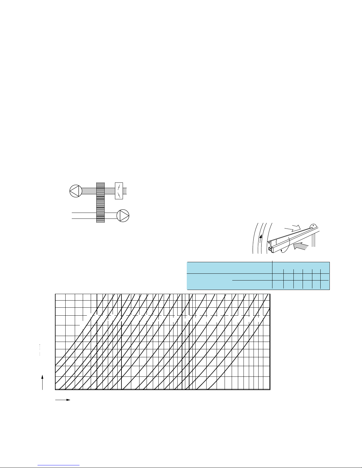
Angle, degrees 1°– 6°
123456
Pressure Standard foil spacing 4,8 2,0 1,3 0,9 0,7 0,6
differential, p1-p3, in WG Wider foil spacing 2,8 1,0 0,6 0,4 0,4 0,3
Leakage flow rates and fan sizing
Leakage between the supply and exhaust air sides cannot
be entirely eliminated in a rotary heat exchanger. But by
locating the fans as shown in Fig. 5, the carry-over of ex-
haust air to the supply air can be eliminated. The pres-
sure differential between the supply and exhaust air ducts
on both sides of the exchanger should be such that p1 >
p4 and p2 > p3. If necessary, an adjusting damper is
installed as shown in Fig. 5 to achieve this.
Leakage at the seals can be minimized by the pressure dif-
ferential between the supply and exhaust air ducts being
as small as possible. Chart 5 shows the leakage flow across
the seal as a function of pressure differential p1 - p3.
Purging sector – carry-over flow
The purging sector is located on the supply air outlet
side, at the point where the rotor passes from the exhaust
air flow path to the supply air flow path. The sector,
which is adjustable between 0 and 6°, should be set to
suit the pressure differential p1 - p3 in the system (see
table below).
If the purging sector of the heat exchanger is set to 0°, a
certain volume of exhaust air will always be transferred to
the supply air, and a certain volume of supply air will
always be transferred to the exhaust air by carry-over.
However, these volumes are equal and cancel one another
out. If the purging sector is correctly adjusted to suit the
prevailing pressure conditions (see the table), complete
purging of the rotor will take place without any air being
lost. However, a certain amount of supply air will be
transferred to the exhaust air by carry-over. This takes
place at the point where the rotor moves from the supply
air duct to the exhaust air duct as it rotates.
The volume carried over is approximately 3% of the
supply air flow at p1-p3 = 0.4 in. WG, and approximate-
ly 1.5% at p1-p3 = 0.8 in. WG, regardless of
the heat exchanger size (rotor speed = 10 RPM).
Tilluft
Frånluft
p3
p1
Frånluft
p4
Tilluft
p2
Fig. 6.
Purging sector
Chart 5
Leakage flow q1
Fig. 5. Heat exchanger on the suction side of both fans
110
120
135
150
190
200
215
240
265
290
320
350
380
420
300 400 500 1 000 2 000 3 000200
4.0
1.6
1.2
0.8
Leakage flow ql, CFM
p1–p3 , IN. WG.
2.0
2.4
3.2
Size 060
170
460
500
095
080
Supply air
Leakage flow ql,CFM
106 148 191 265 371 424 636 848 1272 1696 2120 2756 2968 3392
Size
Supply air
Exhaust air
Exhaust
air
inches WG.

Fläkt Woods 3099 US 03.02 17 Specifications are subject to alteration without notice
PUMA (A–F) Rotary heat exchanger TECHNICAL HANDBOOK
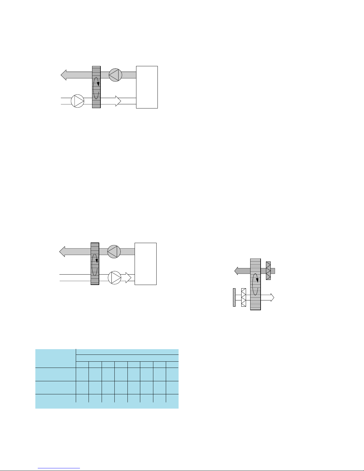
Project design advice
Location of the fan
Question: Is air recirculation permissible?
If air is recirculated, the fans can be located in any posi-
tion. If air recirculation is not permissible, the fans
should be installed as shown in Fig. 7 or Fig. 8 if particu-
larly high purging pressure is required.
Note that the installation shown in Fig. 7 may cause
negativ pressure in the building during the winter.
This is the most common location of the fans. The pres-
sure can be lowered by installing an adjusting damper in
the exhaust air duct upstream of the heat recovery unit.
Question: Is maximum cooling energy recovery desirable?
If the fans are installed as shown in Fig. 8, all of the losses
in the motor and the exhaust air fan and almost all of the
losses in the motor and the supply air fan will be dis-
charged with the exhaust air.
These locations give constant pressure conditions in the
building throughout the year.
Maximum cooling energy recovery will be achieved if the
fans are located so that the heat in the outdoor air and
the fan-generated heat are both transferred to the exhaust
air. This location is also suitable for premises in which
high air cleanliness is demanded.
p3
p1
p4
p2
Rum
p3
p1
p4
p2
Rum
Room
Room
Fig. 7
Fig. 8
Symbols used:
Rotor pressure drop on the supply air side,
∆p1-2, inches.WG
Pressure differential across the purging sector,
p1- p3, inches.WG
Supply air flow downstream of the heat exchanger,
q2, CFM
Exhaust air flow upstream of the heat exchanger,
q3, CFM
Exhaust fan air flow q4
Leakage flow, ql, CFM
Carry-over flow, qm, CFM
Rating factor for exhaust air =ƒ
Calculation example:
Given: PUMB-240 installed as shown in Fig. 5
q2= q3= 18 000 CFM
∆p = 0.66 in.WG
p1- p3= 1.6 in.WG
From Chart 5, ql= 540 CFM
From the previous page, the carry-over air flow
would amount to approximately 2% of the supply air
flow, q2 (3% at 0.4 inches WG; 1.5% at 0.8 inches WG.
The exhaust air fan thus operates at a flow which is
around 5% higher than the exhaust air flow rate from the
room (q3).
q4 =ƒ*q3
ƒ = 18000 + 540 + 0.02*18000 = 1.05
18000
q4 = 1.05 * 18000 = 18900 CFM
q3+q1+qm
ƒ= q3
Fläkt Woods 3099 US 03.02 18 Specifications are subject to alteration without notice
PUMA (A–F) Rotary heat exchanger TECHNICAL HANDBOOK
Project design advice
Filters
Experience has shown that the ECONOVENT rotor is
very insensitive to clogging during operation, in spite of
the dense structure of passages. This is due to the fact
that the direction of air flow through the rotor is contin-
ually reversing, which has an excellent self-cleaning
effect. The laminar flow through the rotor is also a con-
tributory factor to the very rare occurrence of clogging of
the rotor.
If either of the air streams has a high dust content, the
particles usually adhere to the rotor surface, and very
rarely settle inside the passages. As a result, the particles
are blown away from the rotor surface when the direction
of air flow reverses.
In many installations, the rotor is stationary during
parts of the year. To protect the rotor from deposits and
clogging, the supply air filter of the system should be
located upstream of the rotor.
If the rotor should become clogged, it can normally
easily be cleaned by vacuum cleaning. Compressed air,
low-pressure steam and certain types of grease solvents
can also be used.
Clogging problems may nevertheless occasionally
occur in practice. In the event of doubt, it is therefore
better to fit a filter rather than determine at a later date
that a filter is needed (see Fig. 11).
In order to prevent fouling and clogging of the rotor
during the construction period, the regular filters should
be in position, and the rotor should always be rotating
when the fans in the system are running.
Insertion loss ∆Lw, dB
Rotor version Octave band, mid-frequency, Hz
63 125 250 500 1000 2000 4000 8000
Non-hygroscopic
rotor, aluminium 344345 69
Hygroscopic
rotor, aluminium 323456 79
Composite rotor 3 3 3 4 5 6 10 14
The fan locations shown in Fig. 9 may give rise to prob-
lems, since it may be difficult to achieve correct pressure
balance.
Question: Is maximum heat recovery desirable?
If the fans are installed as shown in Fig. 10, all of the
power supplied to the exhaust air fan motor and almost
all of the power supplied to the exhaust air fan motor will
be utilized.
The location provides constant pressure conditions in the
building throughout the year.
Maximum heat recovery will be obtained if the fans are
installed so that the heat from the exhaust air fan is
utilized (Fig. 10). This fan location can be used only in
systems in which air recirculation is permissible.
In cases where the exhaust air is polluted and return air
cannot be used, a correct pressure balance must be
obtained on both sides of the rotor.
Pressure conditions: p1> p4, p2> p3.
INSERTION LOSS ∆Lw, dB
Rum
Rum
Room
Room
Fig. 9
Fig. 10
Frånluft
TilluftUteluft
1)
2)
Outdoor air
Fig. 11 Supply air
Exhaust air
1) A basic filter should preferably be installed, particularly if the dust consists
of large particles, or of oily, tacky or adhering particles. If a filter is not
installed, space should be left for installing a filter at a later date.
2) The filter class should be selected to suit the requirements of the
premises.
Inspection facilities
An inspection section or a duct with inspection cover
should be connected to the heat recovery unit to enable
the rotor to be inspected and serviced. However, if unit
sections with good access facilities are connected directly
to the heat recovery unit, these may be used for inspection.

Fläkt Woods 3099 US 03.02 19 Specifications are subject to alteration without notice
PUMA (A–F) Rotary heat exchanger TECHNICAL HANDBOOK
Control of rotary heat exchangers
Either on/off or continuously variable control can be em-
ployed for controlling the rotor speed.
If on/off control is employed, the temperature effici-
ency will be either zero or a maximum.
In continuously variable control, the rotor speed is var-
ied from rest to maximum speed in a continuous manner.
The temperature and moisture efficiencies as a function
of the rotor speed are shown in Chart 6.
During periods when no heat recovery is required, the
rotor speed will be so low that the efficiency will be close
to zero, although the rotor will still be purged.
For particulars of selecting the drive equipment for
on/off or continuously variable speed, refer to separate
instructions from Munters International Inc.
Chart 6
Example. Heat recovery - Variable speed
The heat exchanger rotor speed is controlled steplessly by
temperature sensors for constant supply air temperature,
constant room temperature or constant exhaust air tem-
perature.
0 102030405060708090
0
20
40
60
80
100
Verkningsgrad η%
100
% av max. varvtal
ηt
ηx
Hygroskopisk rotor
Kompositrotor
Rum
RC-T
RC
RPM
DM
~
Ingår i PUM
Fig. 13
RC
RPM
DM
ST
SV
RC
T
DT
K
= Varvtalsregulator = Spjällreglermotor
= Reglercentral för temperatur
= Kontaktor
= Drivmotor för värmeväxlare
= Ventilreglermotor
= Temperaturgivare
= Differenstermostat
Room
Included in PUM
Efficiency η, %
% of max. speed
= Speed controller
= Temperature control unit
= Heat exchanger drive motor
= Damper motor
= Temperature sensor
= Proportional thermostat
= Differential thermostat
= Contactor
Composite rotor
Hygroscopic rotor
Fig. 12.
If the air is admitted at an angle to the rotor face
In systems in which the air impinges on the rotor face at
an angle as shown in Fig. 12, the rotor could start to turn
because of this inclined angle of flow. This may cause
undesirable heat recovery due to the rotor rotating even
when the heat exchanger is shut down.
In such installations, guide vanes should be fitted at
the rotor inlet in order to deflect the air so that it will
flow at right angles to the rotor face.
If the heat exchanger is located on the delivery side of
the fan, a space should always be provided between the
fan outlet and the rotor to enable the air leaving the fan
outlet to distribute itself evenly over the whole of the
rotor area.
Control Systems
Project design advice

Fläkt Woods 3099 US 03.02 20 Specifications are subject to alteration without notice
PUMA (A–F) Rotary heat exchanger TECHNICAL HANDBOOK
Control
Example 4. Speed detector
Variable speed: The speed detector monitors the rotor
speed. An alarm will be initiated if the rotor speed is
lower than that demanded by the speed controller. The
magnet, magnetic sensor and mounting bracket are
included in the supply.
Constant speed: The speed detector consists of a mag-
net, a magnetic sensor and an alarm relay. The alarm
relay is preset for an alarm delay time of 120 seconds.
This time corresponds to the lowest rotor speed of
approximately 0.25 rpm. In order to avoid an alarm
when the rotor is intended to be stationary, the alarm
relay should be wired so that an alarm can be initiated
only when the system requires heating or cooling energy
recovery (see the instructions).
Rotor
Magnet Impulsgivare
Larm, lampa e.dyl.
Larmrelä
Fig. 16b
Fig. 16a
Nät
220 V
RC
RPM Rotor
Fästplåt
Magnet
Impulsgivar
e
Magnetic
sensor
Mounting bracket
200 V
supply
Magnetic sensor
Alarm relay
Alarm, alarm lamp or the like
Magnet
Magnet
Example 2. Heating and cooling energy recovery
The temperature sensor 5 maintains the exhaust air
temperature or room temperature constant via the con-
trol unit 4 which, on a drop in outdoor air temperature,
begins by reducing the cooling output. If the sensor 2
senses a higher temperature than sensor 3 , the rotor will
run at maximum speed, which is known as summer case
control. If no cooling is carried out and the temperature
drops further, the rotor speed will increase. At maximum
speed and increased heat demand, the supply air temper-
ature is controlled by means of the reheater.
1 Speed controller
2 Temperature sensor
3 Temperature sensor
4 Control unit of a make available on the market
5 Temperature sensor
6 PUMZ - 21 or equivalent differential thermostat
Example 3. Cooling energy recovery - maximum speed
If the temperature sensors 2 and 3 of the differential
thermostat sense that the supply air temperature is higher
than the exhaust air temperature, the motor will run at
maximum speed for cooling energy recovery.
Rum
RC
RPM
DM
~
DT
1
3
2
~~
Rum
1
3
2
RC
RPM
DM
DT
6
5
4
RC
T
ST SV SV
+–
Fig. 14
Fig. 15
Room
Room
1 PUMZ - 21
differential thermostat
2 Temperature sensor
3 Temperature sensor
are included in 1
}are included in 6
}
Table of contents
Popular Heater manuals by other brands


Rohnson
Rohnson R-8070 instruction manual

Greentouch
Greentouch DF1904-289 Assembly / care & use instructions

Brentwood Appliances
Brentwood Appliances H-Q600BK Operating and safety instructions

Frico
Frico Elztrip EZ300 Series Mounting and operating instructions

Travis Industries
Travis Industries Liberty manual

Goldair
Goldair GCT270 operating instructions

Rowi
Rowi HKH 2000/2/1 ODT Premium Original instruction manual

L.B. White
L.B. White Premier CS700 Owner's manual and instructions

Sears, Roebuck and Co.
Sears, Roebuck and Co. 583.409030 Assembly, operating instructions and parts list

BAWA
BAWA DBEPZMA00D Assembly and operating manual

Reece
Reece Kado Lussi installation instructions

Rinnai
Rinnai INFINITY 16 User instruction