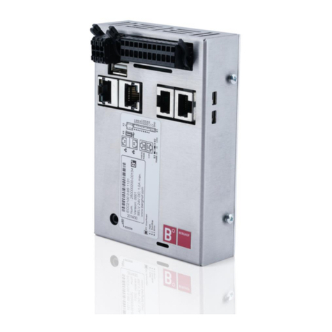
Trio MC6N-ECAT User manual

QUICK START GUIDE
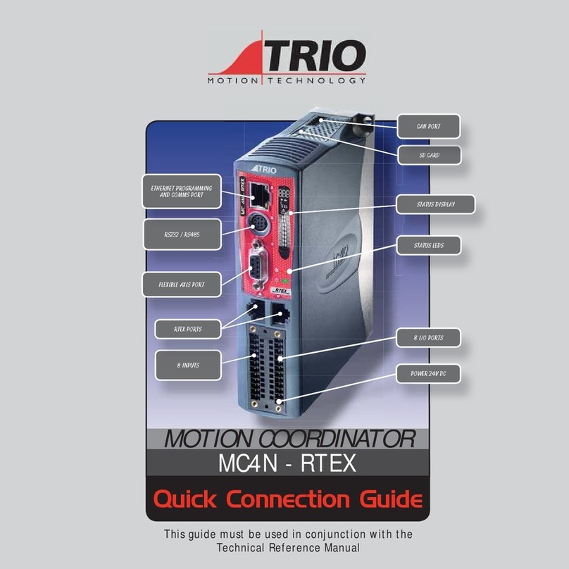
PROGRAMMING PORT
ETHECAT PORT
STATUS LEDS
BACKLIT DISPLAY
FLEXIBLE AXIS PORT
RS232 / RS485 PORT
POWER - I/O - WDOG
CANBUS & SD CARD
CHASSIS EARTH
SCREW
MC6N-ECAT
P960 - P965

2
MINIMUM CONNECTIONS
PROGRAMMING PORT
ETHECAT PORT
0V
24V
OPTIONAL CONNECTIONS
Serial ports
Auxiliary Flexible Axis Port
I/O Connections
Enable (Watchdog)
CONNECTORS
I/O / Power (24V) connector:
Note: Use ferrules on all wires for best connection.
1. Connection: Push wire into hole of connector. Tighten
screw. Insert connector into MC6N.
2. Removal: Reverse the procedure.
SAFETY WARNING
During the installation or use of control systems, users of Trio products must ensure that there is no possibility of injury to any
person or damage to machinery.
Control systems, especially during installation, can malfunction or behave unexpectedly. Bearing this in mind, users must
ensure that even in the event of a malfunction or unexpected behaviour, the safety of an operator or programmer is never
compromised.

3
RJ45 ETHERNET CONNECTOR (TOP)
A standard Ethernet connector is provided for use as the primary programming interface.
The Trio programming software, Motion Perfect 4.3 and above, must be installed on a Windows based PC that
is tted with an Ethernet connection. The IP address is displayed on the MC6N display for a few seconds after
power-up or when an Ethernet cable is plugged in.
The Standard Ethernet connection may also be used for Ethernet-IP, Modbus and other factory communications.
ETHERCAT PORT
The MC4N acts as an EtherCAT master. EtherCAT drives and I/O devices are normally connected in a chain.
Ethernet standard pin assignment:
Pin Signal Description
1TD+ Transmission data +
2TD- Transmission data -
3RD+ Receive data +
6RD- Receive data -
Symetric or cross-over cables can be used between EtherCAT devices. Minimum CAT 5 shielded SF/UTPcable is recommended.
ETHERCAT NETWORK DETECTION
EtherCAT Intelegent drives Window in Motion Perfect

4
SERIAL CONNECTIONS (8 WAY MINI-DIN)
Pin Function Note
1 RS485 Data In A Rx+ Serial Port #2
2 RS485 Data In B Rx-
3 RS232 Transmit Serial Port #1
4 0V Serial
5RS232 Receive Serial Port #1
65V Output 150mA max*
7 RS485 Data Out Z Tx- Serial Port #2
8 RS485 Data Out Y Tx+
* Current shared with encoder port
FLEXIBLE AXIS PORT (9 WAY D-TYPE)
Pin Encoder Stepper Axis Absolute Encoder
1 Enc. A Step + Clock
2Enc. /A Step - /Clock
3 Enc. B Direction + --------
4Enc. /B Direction - --------
5 0V Serial/Encoder 0V Serial/Encoder 0V Serial/Encoder
6 Enc. Z Enable + Data
7Enc. /Z Enable - /Data
85V* 5V* 5V*
9Not Connected Not Connected Not Connected
*Current limit is 150mA max shared with serial port.
8
7
6
5
4
3
1
2
5
4
3
2
1
9
8
7
6

5
SHIELDING THE FLEXIBLE AXIS PORT
Ensure that:
1. The shield screw is grounded as close to the MC6N as possible.
2. 0V connection is NOT used for terminating screens.
3. Pin 5 of Encoder/Stepper plug is connected to 0V on drive.
4. Encoder cable screen is clamped to 9 way D shell.
5. The MC6N 24V supply has common 0V with the drive(s).
WHEN WIRING MC6N STEPPER OUTPUT TO A DIFFERENTIAL
INPUT STEPPER DRIVE, USE THE 0V AND SHIELD CONNECTIONS
SHOWN FOR THE ENCODER. THE STEPPER DRIVE MUST HAVE ITS
COMMON 0V CONNECTED TO THE MC6N.
5
1
2
3
4
6
7
0V
A+
A-
B+
B-
Z+
Z-
CONNECTOR SHELL
Enc 0V
Quadrature A
Quadrature B
Z Marker Pulse
SHIELD SCREW
ENCODER INPUT (9 WAY D-TYPE)
Encoder Output 0V MUST be connected to pin 5
*
*

6
I/O CONNECTOR
Not Used
Not Used
I/O 8
I/O 9
I/O 10
I/O 11
I/O 12
I/O 13
I/O 14
I/O 15
I/O 24V
24V
Input 0
Input 1
Input 2
Input 3
Input 4
Input 5
Input 6
Input 7
I/O 0V
0V
Enable
(Watchdog)
I/O CIRCUITS
Optical
Output
Control
Signal
Optical
Input
Signal
I/O 24V
I/O 0V
Protected
Switch
I/O Pin
6k8
Optical
Input
Signal
I/O 0V
Input Pin
2k7 on Inputs 0 - 3
6k8 on all other inputs
Inputs 0 - 3 have fast
opto-couplers for use as
axis registration inputs.
Inputs 4 - 7 may also
be used as registration
inputs.
Inputs / Outputs 8 - 15

7
AMPLIFIER ENABLE (WATCHDOG) RELAY OUTPUT
An internal relay may be used to enable external ampliers when the controller has
powered up correctly and the system and application software are ready. The amplier
enable is a single pole solid state relay with a normally open “contact”. The enable
relay contact will be open circuit if there is no power on the controller OR an axis
error exists OR the user program sets it open with the WDOG=OFF command.
ETHERCAT DRIVES WILL BE ENABLED VIA THE ETHERCAT NETWORK SO THE
“AMPLIFIER ENABLE” CONNECTION IS NOT NORMALLY REQUIRED.
ALL NON ETHERCAT STEPPER AND SERVO AMPLIFIERS MUST BE INHIBITED
WHEN THE AMPLIFIER ENABLE OUTPUT IS OPEN CIRCUIT.
An additional safety relay may be required so as to meet machine safety approvals.
Enable
Not Used
Not used
Input/Output 8
Input/Output 9
Input/Output 10
Input/Output 11
Input/Output 12
Input/Output 13
Input/Output 14
Input/Output 15
Input/Output 24V
24V
Input 0
Input 1
Input 2
Input 3
Input 4
Input 5
Input 6
Input 7
Input/Output 0V
0V
Amplier
Enable 1
Amplier
Enable 2
To other axis enables
24V 0V 0V
Enable
CONTROLLER SERVO AMPLIFIER

8
DISPLAY
The IP address and subnet mask of the MC6N is shown on the LCD display for a few seconds
after power-up. The factory default IP address is 192.168.0.250. This can be changed using
the IP_ADDRESS command via the Motion Perfect software toolor SD Card.
Display
Example Description Details
SYS
Displayed on
controller
start
960
Model code :
Displayed on
power up
P960 : 2 axes
P961 : 4 axes
P962 : 8 axes
P963 : 16 axes
P964 : 32 axes
P965 : 64 axes
192.168 .0.25 0 IP Address :
Displayed on power up OR after
ethernet connection for 15
seconds
Enable status
Error codes
Ann : Error on Axis nn
Unn : Unit error on slot nn
Caa : Conguration error on
unit nn, ie: too many axes
E04 : VR/TABLE corrupt entry
IP Address / Run / Error code
(see table below)
EtherCAT Communications
active
EtherCAT detection (flashing)
EtherCAT detected (steady)
I/O channels On / OFF
Error
Enable status LED
Power LED

9
5-WAY CANBUS CONNECTOR
This is a 5 way 3.5mm pitch connector. The connector is used both to provide the 24 Volt power to
the MC6N CAN circuit and provide connections for I/O expansion via Trio’s CAN I/O expanders. A
24V dc, Class 2 transformer or power source should be used.
This 24V input is internally isolated from the I/O 24V and main 24V power.
THE CAN CONNECTOR MAY BE LEFT UNUSED. THE MC6N IS GROUNDED VIA THE METAL
CHASSIS. FIT A SHORT SHIELD CONNECTION BETWEEN THE CHASSIS EARTH SCREW AND
THE EARTHED METAL MOUNTING PANEL / PLATE.
SD CARD
The SDHC Card (high density) may be used for storing or transfering programs, recipes and data to and from the MC6N. The card
must be FAT32 format and a maximum 32Gb size.
SD CARDS MAY BE FAT16 FORMATTED WHEN PURCHACED. RE-FORMAT IN A PC TO FAT32 PRIOR TO USE.
CAN 0V
C-Low
C-High
CAN 24V

10
NETWORK SETUP
Network connection
Set IP_ADDRESS in MC6N to an available unused address.
It MUST match the subnet in use. Set the PC to use
DHCP server.
Note: the MC6N always has a xed IP address.
Point-to-point or closed network
(No DHCP server)
The PC MUST be set to a xed IP_ADDRESS.
The rst 3 “octets” MUST be the same as the MC6N and
the last MUST be dierent, but not 000, 254 or 255.
Setting a xed IP address
In Windows 7. Open “Network and Sharing Centre” then change “Adapter
Settings”. Select the properties of the Local Area Network and the IPv4
properties. The IP Address is set to 192.168.0.100 with subnet mask set to
255.255.255.0. Assuming that the MC6N has IP_ADDRESS=192.168.0.250 or
similar.
SwitchPC Laptop MC6N
PC Laptop MC6N
DCHP Server
Example : 192.168.0.100 Example : 192.168.0.250
SwitchPC Laptop MC6N
PC Laptop MC6N
DCHP Server
Example : 192.168.0.100 Example : 192.168.0.250

11
CHASSIS MOUNTING DIMENSIONS (LOOKING FROM FRONT)
M4 screws should be used in 2 places to mount the MC6N to an unpainted metal
panel.
The best EMC performance is obtained when the MC6N is attached from the shield
screw (marked) using a at braided conductor with a cross section of 4mm x 1mm.
Do NOT use a circular section wire or run the braid to a central star point.
ENSURE THAT THE VENTILATION SLOTS AT THE TOP AND BOTTOM OF THE
MC6N ARE KEPT CLEAR TO ENSURE A FREE FLOW OF AIR THROUGH THE
MODULE.
38.6
19.3 19.3
4
145.8
4
4.5
4.5
Shield Screw

UK | USA | CHINA | INDIA
WWW.TRIOMOTION.COM
THE MOTION SPECIALIST
CAD data Drawings to aid packaging and mounting are available in various formats from the Trio web site. Products should be
wired by qualied persons.
Specications may change without notice. E & OE
Quick Start v1 March 2018
154mm
184mm
56mm
186mm
122mm
35mm
226mm
132mm
35mm 135mm
122mm
35mm
270.97mm
212.97mm
40mm
200.35mm
146.35mm
34.0mm
120mm
157mm
107mm
40mm
147mm
15mm15mm15mm
17mm17mm
120mm
157mm
40mm 120mm
157mm
40mm
170mm
129mm
25mm
130mm
26mm 85mm
120mm
157mm
40mm
This manual suits for next models
2
Table of contents
Other Trio Control System manuals
