manuals.online logo
Brands
  1. Home
  2. •
  3. Brands
  4. •
  5. GE
  6. •
  7. Industrial Equipment
  8. •
  9. GE TLE 30 Series User manual

GE TLE 30 Series User manual

Critical Power
TLE Series 30 & 40 CE S1
Installation Guide / Installationsanleitung / Guía de instalación / Guide de installation
Modifications reserved
Page 1/8
GE_UPS_ISG_TLE_SCE_30K_40K_1XX_V010.docx
Installation Guide TLE Series 30 & 40 CE S1
GB This "Installation Guide" shall be used exclusively for UPS standard configurations.
If optional cabinets are included with the UPS, please refer to those accompanying manuals for installation.
DE Diese "Installationsanleitung" gilt nur für USV Standardanlagen.
Konsultieren Sie die beiliegende Installationsanleitung für Anschluss und Installation für Optionen in zusätzlich
mit der USV gelieferten Schränken.
ES Esta “Guía de instalación” es válida solo para la instalación de SAI estándar.
Si el SAI incluye opciones ubicadas en armarios adicionales utilizar el manual de instalación especifico anexo.
FR Cette "Guide d'installation" est valide seulement pour l'installation de ASI standard.
Si l’ASI est livrée avec des options en armoires additionnelles il faut utiliser le manuel l’installation spécifique
annexe.
GB UPS installation and connection must be performed by QUALIFIED SERVICE PERSONNEL
only.
Refer to the “Safety prescriptions - Installation” described on the “UPS Safety Rules”.
DE Installation und Verkabelung der USV darf nur durch QUALIFIZIERTES SERVICE-PERSONAL
ERFOLGEN.
Die “Sicherheits- und Installationsvorschriften“, wie beschrieben in den beiliegenden “UPS
Safety Rules”, müssen beachtet werden.
ES La instalación y cableado del SAI debe ser realizada por PERSONAL CUALIFICADO.
Respectar las “Normas de seguridad -Instalación” describidlas en la “UPS Safety Rules”.
FR L’installation et le câblage de l’ASI doivent être effectués SEULEMENT PAR DU PERSONNEL
QUALIFIÉ.
Respecter les “Consignes de sécurité - Installation” décrites dans l’annexe “UPS Safety
Rules”.
GB Check for sufficient floor and elevator loading capacity.
Be aware of the heavy weight of the UPS, pay attention when
moving the UPS cabinet.
Ensure that the cabinet is not damaged when moving by forklift.
DE Achten Sie auf ausreichende Tragfähigkeit des Bodens und des
Aufzugs.
Die USV ist sehr schwer, daher muss der Schrank mit großer
Vorsicht verschoben werden.
Achten Sie darauf, den Schrank nicht mit den Gabelarmen zu
beschädigen.
ES Verifique que existe suficiente pavimento y que la capacidad de carga del carro elevador es la suficiente.
El SAI es muy pesado, tener muy cuidado cuando se mueve el armario.
Asegurarse que no se daña el equipo mientras se mueve con la carretilla elevadora.
FR Contrôler que la résistance ou sol et la force portante de l’engin de levage utilisées soient suffisantes.
L’ASI est très lourd, faire très attention lors du déplacement de l’armoire.
Ne pas endommager l’armoire avec les fourches de l’élévateur.
GB A damaged UPS must never be installed or connected to mains or battery!
DE Eine beschädigte USV-Anlage darf NIE installiert, ans Netz oder an die Batterie
angeschlossen werden!
ES En caso de que el SAI presente algún daño no proceda a la instalación ni a la conexión a la
red ni a la batería!
FR Dans le cas où l’ASI arrive endommagée, ne pas procéder à l’installation ou au
raccordement du réseau et de la batterie!
Critical Power
TLE Series 30 & 40 CE S1
Installation Guide / Installationsanleitung / Guía de instalación / Guide de installation
Modifications reserved
Page 2/8
GE_UPS_ISG_TLE_SCE_30K_40K_1XX_V010.docx
Installation Guide TLE Series 30 & 40 CE S1
GB Heat evacuation from UPS room.
The heat must be evacuated from the environment with a proper cooling / ventilation system provided by the user.
DE Belüftung des USV-Raumes.
Die an die Umgebung abgegebene Verlustwärme der USV muss mit einem geeigneten Kühl-
/Lüftungssystem der Umgebung wieder entzogen werden.
ES Flujo de ventilación local del SAI.
El calor transmitido al ambiente por el SAI debe ser evacuado con un sistema de ventilación / climatización adecuada.
FR Flux ventilation local ASI.
La chaleur expulsée de l’ASI doit ensuite être évacuée vers l’extérieur par un système de climatisation ou
ventilation appropriée.
UPS disposition
Aufstellung USV
Posicionamiento del SAI
Emplacement de l’ASI
Access to the connection terminals
Zugang zu den Anschlussklemmen
Acceso a la regleta de conexión
Accès aux bornes de raccordement
GB UPS commissioning must be performed by GE
SERVICE ENGINEER only!
DE Die Inbetriebnahme der USV darf nur durch
einen SERVICETECHNIKER der GE
vorgenommen werden!
ES La puesta en marcha inicial del SAI debe ser
realizada solo por un TÉCNICO CUALIFICADO
GE!
FR La mise en service initiale de l’ASI doit être
effectuée seulement par un TECHNICIEN DE
SERVICE GE!
TLES_030-040_S1_UPS ventilation_Raised floor_01IT-a
Uscita Aria
Entrata Aria
TLES_030-040_S1_UPS ventilation_Raised floor_01IT-a
Entrata Aria
Uscita Aria
Min.
500mm / 19.7"
TLES_030-040_S1_UPS disposition_GE_01a
TLES_030-040_S1_RPA disposition_01GB-a
UPS 1 UPS 2 UPS 3 UPS 4 UPS 5 UPS 6
A
B
TLES_030-040_S1_UPS connection_Rear_01
Input mains / Battery / Output load
Netzeingang / Batterie / Lastausgang
Entrada red / Batería / Salida carga
Entré réseau / Batterie / Sortie chargerico
Ingresso rete / Batteria / Uscita carico
Ingangsspanning / Batterij / Uitgang belasting
Zapojení vstupní síte / Baterie / Zapojení výstupní záteže
Wejscie sieci zasilajacej / Bateria / Obciazenie
Critical Power
TLE Series 30 & 40 CE S1
Installation Guide / Installationsanleitung / Guía de instalación / Guide de installation
Modifications reserved
Page 3/8
GE_UPS_ISG_TLE_SCE_30K_40K_1XX_V010.docx
Installation Guide TLE Series 30 & 40 CE S1
GB Input/output terminals must be tightened with a proper screwdriver applying torsion force 1.8÷3 Nm /
25mm2and 2.5÷3.5 Nm / 50mm2.
DE Geeigneten Schraubendreher verwenden zum Anziehen der Klemm-Schrauben für Netzein- und
Lastausgang mit 1.8÷3 Nm / 25mm2und 2.5÷3.5 Nm / 50mm2!
Die Kabel mit dem entsprechenden Kabelbinder befestigen.
ES Utilizar herramienta con fuerza de torsión 1.8÷3 Nm / 25mm2y 2.5÷3.5 Nm / 50mm2para apretar los
tornillos de las terminales de conexión. Los cables deben ser bloqueados con Ia brida.
FR Utiliser des outils avec force de serrage de 1.8÷3 Nm / 25mm2et 2.5÷3.5 Nm / 50mm2pour serrer les vis
des bornes de raccordement.
Les câbles doivent être fixés avec une frette sur le châssis.
Common Mains Input for Rectifier & Bypass / Gemeinsame Netzversorgung für Gleichrichter und Bypass
Conexión con Red Común por Rectificador y Bypass / Raccordement Réseau Commune pour Redresseur et Bypass
L1-1
L1 Rectifier + Bypass / L1 Gleichrichter + Bypassnetz / L1 Rectificador + Bypass / L1 Redresseur + Bypass
L2-1
L2 Rectifier + Bypass / L2 Gleichrichter + Bypassnetz / L2 Rectificador + Bypass / L2 Redresseur + Bypass
L3-1
L3 Rectifier + Bypass / L3 Gleichrichter + Bypassnetz / L3 Rectificador + Bypass / L3 Redresseur + Bypass
N
Neutral Mains Input / Nullleiter Netz / Entrada Neutro Red / Neutre Entrée Réseau
PE
Ground Mains Input / Erde Netzeingang / Tierra Entrada Red / Terre Entrée Réseau
Output load / Last Ausgang / Salida carga / Sortie charge
L1
Phase L1 Load / Phase L1 Last / Fase L1 Carga / Phase L1 Charge
L2
Phase L2 Load / Phase L2 Last / Fase L2 Carga / Phase L2 Charge
L3
Phase L3 Load / Phase L3 Last / Fase L3 Carga / Phase L3 Charge
N
Neutral Output Load / Nullleiter Last / Neutro Salida Carga / Neutre Sortie Charge
PE
Ground Output Load / Erde Last / Tierra Salida Carga / Terre Sortie Charge
External Battery / Batterie Externe / Batería Esterna / Batterie Externe
+
Positive pole / Plus-Pol / Polo positivo / Pôle positif
-
Negative polo / Minus-Pol / Polo negativo / Pôle négatif
PE
Ground Battery / Erde Batterie / Tierra baterìa / Terre batterie
GB The interconnection links BR1, BR2 and BR3 MUST BE FITTED!
DE Die Verbindungsbrücken BR1, BR2 und BR3 MÜSSEN MONTIERT SEIN!
ES Los puentes de unión BR1, BR2 e BR3 DEBEN ESTAR CONECTADOS!
FR Les ponts de raccordement BR1, BR2 et BR3 DOIVENT ÊTRE RACCORDÉS!
TLES_030-040_S1_UPS connection common_Rear_01GB
+_
PE
BR1 BR2 BR3
PE
L1-1 L2-1 L3-1
N
L3 N
L2
L1
PE
PE
Load
1 - Rectifier mains
PE
Battery
BR4
A
Critical Power
TLE Series 30 & 40 CE S1
Installation Guide / Installationsanleitung / Guía de instalación / Guide de installation
Modifications reserved
Page 4/8
GE_UPS_ISG_TLE_SCE_30K_40K_1XX_V010.docx
Installation Guide TLE Series 30 & 40 CE S1
Separate Mains Input for Rectifier and Bypass / Getrennte Netzversorgung für Gleichrichter und Bypass
Conexión con Redes Separadas por Rectificador y Bypass / Raccordement avec Réseau Séparées pour Redresseur et Bypass
GB Connect a single input Neutral to Bypass Mains (inside the UPS, common Neutral for Bypass & Rectifier).
DE Getrennte Netzversorgung Gleichrichter und Bypass: ein einzelnen Nullleiter an dem Bypass Netz
anzuschließen (in der USV Anlage sind die Gleichrichter und Bypass Nullleiter gemeinsam).
ES Redes separadas Rectificador y Bypass: conectar un único conductor de entrada de Neutro a la entrada
de red de Bypass (dentro del UPS el Neutro de Bypass y del Rectificador es común).
FR Réseau séparé Redresseur et Bypass: connectez une seule entrée Neutre aux connecteurs du Bypass (à
l‘intérieur de l'ASI, neutre commun pour Bypass et Redresseur).
L1-1
Phase L1 rectifier / Phase L1 Gleichrichter / Fase L1 rectificador / Phase L1 redresseur
L2-1
Phase L2 rectifier / Phase L2 Gleichrichter / Fase L2 rectificador / Phase L2 redresseur
L3-1
Phase L3 rectifier / Phase L3 Gleichrichter / Fase L3 rectificador / Phase L3 redresseur
L1-2
Phase L1 bypass / Phase L1 Bypass / Fase L1 bypass / Phase L1 bypass
L2-2
Phase L2 bypass / Phase L2 Bypass / Fase L2 bypass / Phase L2 bypass
L3-2
Phase L3 bypass / Phase L3 Bypass / Fase L3 bypass / Phase L3 bypass
N1
Neutral (rectifier / bypass) / Nullleiter (Gleichrichter / Bypass) / Neutro (rectificador / bypass) / Neutre (redresseur / bypass)
PE
Ground Mains Input / Erde Netz / Tierra Entrada Red / Terre Principale
Output load / Last Ausgang / Salida carga / Sortie charge
L1
Phase L1 Load / Phase L1 Last / Fase L1 Carga / Phase L1 Charge
L2
Phase L2 Load / Phase L2 Last / Fase L2 Carga / Phase L2 Charge
L3
Phase L3 Load / Phase L3 Last / Fase L3 Carga / Phase L3 Charge
N
Neutral Output Load / Nullleiter Last / Neutro Salida Carga / Neutre Sortie Charge
PE
Ground Output Load / Erde Last / Tierra Salida Carga / Terre Sortie Charge
External Battery / Batterie Externe / Batería Esterna / Batterie Externe
+
Positive pole / Plus-Pol / Polo positivo / Pôle positif
-
Negative polo / Minus-Pol / Polo negativo / Pôle négatif
PE
Ground Battery / Erde Batterie / Tierra baterìa / Terre batterie
GB The interconnection links BR1, BR2 and BR3 MUST BE REMOVED!
DE Die Verbindungsbrücken BR1, BR2 und BR3 MÜSSEN ENTFERNT SEIN!
ES Los puentes de unión BR1, BR2 e BR3 DEBEN SER QUITADOS!
FR Les ponts de raccordement BR1, BR2 et BR3 DOIVENT ÊTRE ENLEVÉS!
BR1 BR2 BR3 PE
PE
L3 N
L2
L1
PE
L1-1
N
L1-2
L2-1
L2-2
L3-1
L3-2
PE
Load
1 - Rectifier mains
2 - Bypass mains
PE +_
Battery
TLES_030-040_S1_UPS connection separate_Rear_01GB
A
Critical Power
TLE Series 30 & 40 CE S1
Guida d’installazione / Instalační průvodce / Installatiegids / Przewodnik Instalacyjny
Modifications reserved
Page 5/8
GE_UPS_ISG_TLE_SCE_30K_40K_1XX_V010.docx
Installation Guide TLE Series 30 & 40 CE S1
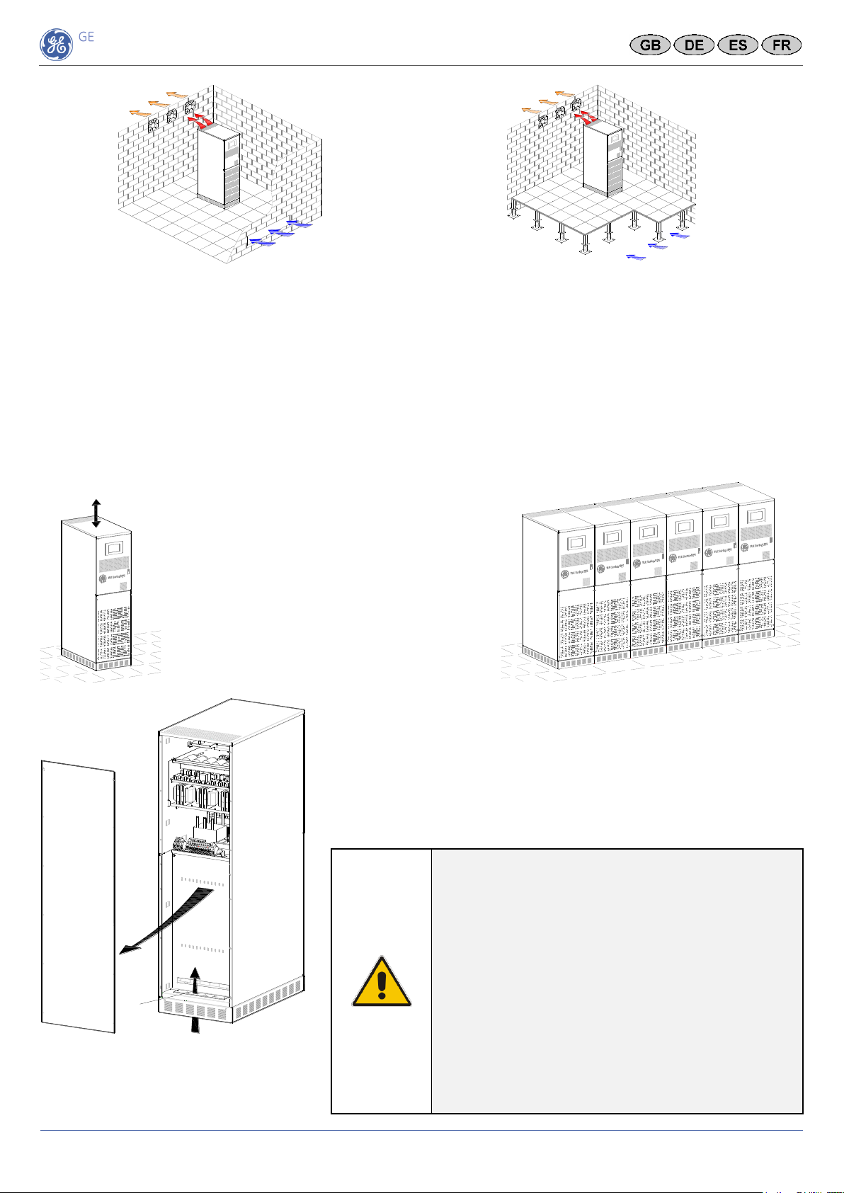
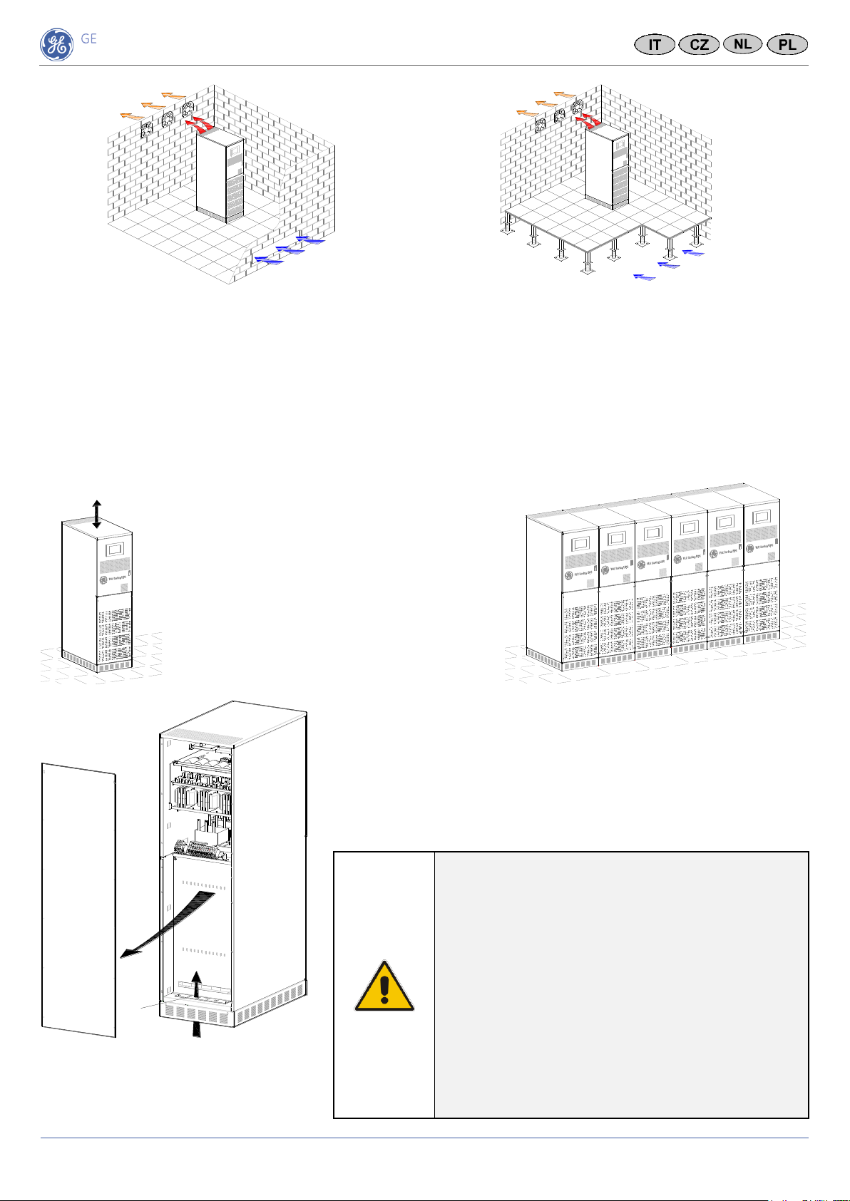
IT Questa “Guida d’installazione” é valida unicamente per l’installazione di un UPS Standard.
In caso l’UPS sia fornito con opzioni in armadi addizionali si prega di consultare lo specifico manuale
d’installazione allegato.
CZ Tento „Instalační průvodce“ je určen výhradně pro UPS ve standardní konfiguraci.
Pokud jsou součástí UPS volitelné skříně, instalace viz prosím k nim přiložené příručky.
ES Deze "Installatiegids" is uitsluitend bedoeld voor standaard UPS configuraties.
Raadpleeg voor het installeren van optionele uitbreidingen de bijbehorende handleidingen.
PL Niniejszy “Przewodnik instalacyjny” ma zastosowanie tylko w przypadku UPS-a w standardowej konfiguracji.
Jeżeli razem z UPS-em ma zostać zainstalowane wyposażenie dodatkowe umieszczone w oddzielnych
szafach, należy postępować zgodnie z zaleceniami zawartymi w instrukcjach obsługi dołączonych do
poszczególnych elementów wyposażenia dodatkowego.
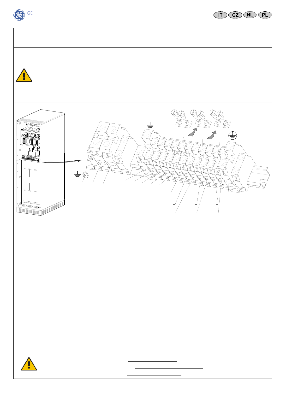
IT L’installazione ed le connessioni del UPS devono essere eseguite unicamente da PERSONALE
QUALIFICATO E COMPETENTE.
Attenersi alle “Prescrizioni di Sicurezza - Installazione” descritte nell’allegato “UPS Safety
Rules”.
CZ Instalaci a zapojení UPS smí provést výhradně KVALIFIKOVANÝ SERVISNÍ PERSONÁL.
Viz „Bezpečností opatření – Instalace“ popsané v oddíle „Bezpečnostní pravidla“.
NL De installatie en bekabeling van de UPS dient te worden uitgevoerd door BEVOEGD
PERSONEEL.
Zie ook de “Veiligheidsvoorschriften bij installatie” in de meegeleverde “UPS
Veiligheidsvoorschriften”.
PL Instalacja UPS-a oraz wszystkie podłączenia przewodów do i z UPS-a mogą być wykonane
tylko przez WYKWALIFIKOWANY PERSONEL.
Patrz “Najważniejsze Zasady Bezpieczeństwa - Instalowanie” opisane w rozdziale “Zasady
Bezpieczeństwa”.
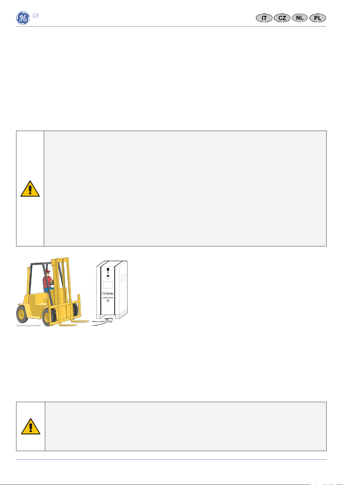
IT Verificare che il pavimento ed il mezzo di sollevamento utilizzato,
abbia una portata sufficiente.
L’UPS è molto pesante, pertanto prestare la massima attenzione
nella movimentazione dell’armadio.
Assicurarsi di non danneggiare l’UPS durante lo spostamento.
CZ Zkontrolujte dostatečnou nosnost podlahy a výtahu.
Mějte na paměti velkou hmotnost UPS, zejména je-li již osazena
bateriemi.
Při přepravě vysokozdvižným vozíkem dejte pozor, aby nedošlo k
poškození skříně.
NL Controleer of de vloer voldoende draagkracht heeft en, indien van toepassing, de lift voldoende
hefvermogen heeft.
Houdt rekening met het aanzienlijke gewicht van de UPS.
Bij gebruik van een vorkheftruck dient u ervoor te zorgen dat de kast niet wordt beschadigd.
PL Należy wcześniej sprawdzić możliwość obciążenia podłogi oraz dźwigu.
Należy pamiętać o dużej wadze UPS-a.
Należy zagwarantować, aby szafa UPS-a nie została uszkodzona podczas transportowania urządzenia przy
pomocy wózka widłowego.
IT In caso l’UPS dovesse presentare dei danni, non procedere all’installazione o al
collegamento alla tensione di rete e di batteria!
CZ Poškozená UPS nesmí být v žádném případě instalována nebo připojena na síť či baterie!
NL Sluit een beschadigd UPS-systeem nooit aan op het lichtnet of op een batterij!
PL Uszkodzony UPS nie może być zainstalowany ani podłączony do sieci zasilającej lub baterii!
Critical Power
TLE Series 30 & 40 CE S1
Guida d’installazione / Instalační průvodce / Installatiegids / Przewodnik Instalacyjny
Modifications reserved
Page 6/8
GE_UPS_ISG_TLE_SCE_30K_40K_1XX_V010.docx
Installation Guide TLE Series 30 & 40 CE S1
IT Flusso ventilazione locale UPS.
Il calore trasmesso all’ambiente dall’UPS deve essere evacuato con un sistema di ventilazione/climatizzazione idoneo.
CZ Odvod tepla z místnosti s UPS.
Uživatel musí zajistit odpovídající ventilační nebo klimatizační systém odvádějící teplo z místnosti.
NL Afgifte van warme lucht uit de UPS-ruimte.
De gebruiker dient te zorgen voor een goed functionerend koel-/ventilatiesysteem voor de afvoer van warme lucht uit
de UPS-ruimte.
PL Odprowadzanie ciepła z pomieszczenia UPS-a.
Użytkownik powinien we własnym zakresie zapewnić właściwy system chłodzenia lub wentylacji i odprowadzania
ciepła z pomieszczenia UPS-a.
Posizionamento dell’UPS
Umístění UPS
Plaatsing van de UPS
Usytuowanie UPS-a
Accesso ai morsetti di connessione
Přístup k AC svorkám
Toegang tot de klemmen voor kabelaansluitingen
Dostęp do zacisków połączeniowych AC
IT La messa in servizio dell’UPS deve essere
eseguita unicamente da un TECNICO DI
SERVIZIO GE!
CZ Uvedení UPS do provozu smí být provedeno
výhradně SERVISNÍMI TECHNIKY GE!
NL Inbedrijfstelling van de UPS dient uitsluitend
te worden uitgevoerd door een GE SERVICE
ENGINEER!
PL Pierwsze uruchomienie nowo
zainstalowanego UPS-a może być wykonane
TYLKO przez INŻYNIERA SERWISOWEGO GE!
TLES_030-040_S1_UPS ventilation_Raised floor_01IT-a
Uscita Aria
Entrata Aria
TLES_030-040_S1_UPS ventilation_Raised floor_01IT-a
Entrata Aria
Uscita Aria
Min.
500mm / 19.7"
TLES_030-040_S1_UPS disposition_GE_01a
TLES_030-040_S1_RPA disposition_01GB-a
UPS 1 UPS 2 UPS 3 UPS 4 UPS 5 UPS 6
A
B
TLES_030-040_S1_UPS connection_Rear_01
Input mains / Battery / Output load
Netzeingang / Batterie / Lastausgang
Entrada red / Batería / Salida carga
Entré réseau / Batterie / Sortie chargerico
Ingresso rete / Batteria / Uscita carico
Ingangsspanning / Batterij / Uitgang belasting
Zapojení vstupní síte / Baterie / Zapojení výstupní záteže
Wejscie sieci zasilajacej / Bateria / Obciazenie
Critical Power
TLE Series 30 & 40 CE S1
Guida d’installazione / Instalační průvodce / Installatiegids / Przewodnik Instalacyjny
Modifications reserved
Page 7/8
GE_UPS_ISG_TLE_SCE_30K_40K_1XX_V010.docx
Installation Guide TLE Series 30 & 40 CE S1
IT Utilizzare appropriato cacciavite per serrare le viti dei morsetti ingresso rete ed uscita carico, con
forza di torsione 1.8÷3 Nm / 25mm2e 2.5÷3.5 Nm / 50mm2.
I cavi devono essere bloccati con le apposite fascette.
CZ Vstupní/výstupní svorky musí být dotaženy odpovídajícím šroubovákem na moment 1.8÷3 Nm /
25mm2- 2.5÷3.5 Nm / 50mm2.
Vstupní/výstupní kabely sepněte pomocí přiložených kabelových pásků “A”.
NL De I/O-aansluitklemmen moeten met een daartoe geschikte schroeven-draaier worden vastgezet
(aandraai-waarde 1.8÷3 Nm / 25mm2- 2.5÷3.5 Nm / 50mm2).
Zet de in- en uitgangskabels vast met de meegeleverde kabelklemmen.
PL Zaciski wejściowe/wyjściowe muszą być dokręcone odpowiednim wkrętakiem, z momentem 1.8÷3 Nm
/ 25mm2- 2.5÷3.5 Nm / 50mm2. Kable należy zamocować do profilu przy pomocy dołączonych opasek.
Connessione con Rete Comune per Raddrizzatore e Bypass / Společný vstup pro usměrňovač – bypass
Gemeenschappelijke voeding Gelijkrichter –Bypass / Wspólne wejście sieci zasilającej dla prostownika i układu obejściowego
L1-1
L1 Raddrizzatore + Bypass / L1 Usměrňovač + Bypassnetz / L1 Gelijkrichter + Bypass / L1 Prostownik + Układ obejściowy
L2-1
L2 Raddrizzatore + Bypass / L2 Usměrňovač + Bypassnetz / L2 Gelijkrichter + Bypass / L2 Prostownik + Układ obejściowy
L3-1
L3 Raddrizzatore + Bypass / L3 Usměrňovač + Bypassnetz / L3 Gelijkrichter + Bypass / L3 Prostownik + Układ obejściowy
N
Neutro Ingresso Rete / Nula síťového vstupu / Nul Net-ingang / Neutralny sieci zasilającej
PE
Terra ingresso rete / Zem síťového vstupu / Aarde Net-ingang / Ochronny sieci zasilającej
Uscita Carico / Výstupní zátěž / Uitgang Belasting / Obciążenie wyjściowe
L1
Fase L1 Carico / Zátěž Fáze L1 / Fase L1 Belasting / Faza L1 Obciążenia
L2
Fase L2 Carico / Zátěž Fáze L2 / Fase L2 Belasting / Faza L2 Obciążenia
L3
Fase L3 Carico / Zátěž Fáze L3 / Fase L3 Belasting / Faza L3 Obciążenia
N
Neutro uscita Carico / Nula Zátěž / Nul belasting / Neutralny obciążenia
PE
Terra uscita Carico / Zem Zátěž / Aarde uitgang Belasting / Ochronny Obciążenia
Batteria esterna / Externì Baterie / Externe Batterij / Zewnętrznej Baterii
+
Polo positivo / Kladný pól / Positieve pool / Biegun dodatni baterii
-
Polo negativo / Záporný pól / Negatieve pool / Biegun ujemny baterii
PE
Terra batteria / Uzemnění bateriové skříně / Aarding batterykast / Ochronny baterii
IT I ponti di collegamento BR1, BR2 e BR3 DEVONO ESSERE MONTATI!
CZ Spojovací můstky BR1, BR2 a BR3 MUSÍ BÝT NAMONTOVÁNY!
NL De BR1, BR2 en BR3 aansluitbruggen MOETEN WORDEN GEMONTEERD!
PL Łączniki mostowe BR1, BR2 i BR3 MUSZĄ ZOSTAĆ ZAMONTOWANE!
TLES_030-040_S1_UPS connection common_Rear_01GB
+_
PE
BR1 BR2 BR3
PE
L1-1 L2-1 L3-1
N
L3 N
L2
L1
PE
PE
Load
1 - Rectifier mains
PE
Battery
BR4
A
Critical Power
TLE Series 30 & 40 CE S1
Guida d’installazione / Instalační průvodce / Installatiegids / Przewodnik Instalacyjny
Modifications reserved
Page 8/8
GE_UPS_ISG_TLE_SCE_30K_40K_1XX_V010.docx
Installation Guide TLE Series 30 & 40 CE S1
Connessione con reti separate per Raddrizzatore e Bypass / Samostatný vstup pro usměrňovač / bypass
Gescheiden voeding Gelijkrichter - Bypass / Rozdzielone wejścia sieci zasilającej dla prostownika i układu obejściowego
IT Collegare un singolo conduttore di Neutro alla linea Bypass, (all’interno dell’UPS i Neutri di Bypass e
Raddrizzatore sono comuni).
CZ Připojte jeden neutrální vodič k bočníkovému vedení (uvnitř UPS jsou neutrální vodiče bočníku a
usměrňovače společné).
NL Sluit een enkelvoudige Neutrale geleider aan op de Bypass-lijn (binnen in de UPS zijn de Neutrale Bypass
en de Gelijkrichter gemeenschappelijk).
PL Podłącz pojedynczy przewód Neutral do linii Bypass (Neutral Bypass i Prostownik występują powszechnie
wewnątrz UPS).
L1-1
Fase L1 Raddrizzatore / Usměrňovač Fáze L1 / Fase L1 gelijkrichter / Faza L1 prostownika
L2-1
Fase L2 Raddrizzatore / Usměrňovač Fáze L2 / Fase L2 gelijkrichter / Faza L2 prostownika
L3-1
Fase L3 Raddrizzatore / Usměrňovač Fáze L3 / Fase L3 gelijkrichter / Faza L3 prostownika
L1-2
Fase L1 Bypass / Bypass Fáze L1 / Fase L1 bypass / Faza L1 układu obejściowego
L2-2
Fase L2 Bypass / Bypass Fáze L2 / Fase L2 bypass / Faza L2 układu obejściowego
L3-2
Fase L3 Bypass / Bypass Fáze L3 / Fase L3 bypass / Faza L3 układu obejściowego
N1
Neutro (Raddrizzatore / Bypass) / Nula (Usměrňovač / Bypass) / Nul (Gelijkrichter / Bypass) / Neutralny (Prostownika / Bypass)
PE
Terra ingresso rete / Zem síťového vstupu / Aarde Net-ingang / Ochronny sieci zasilającej
Uscita Carico / Výstupní zátěž / Uitgang Belasting / Obciążenie wyjściowe
L1
Fase L1 Carico / Zátěž Fáze L1 / Fase L1 Belasting / Faza L1 Obciążenia
L2
Fase L2 Carico / Zátěž Fáze L2 / Fase L2 Belasting / Faza L2 Obciążenia
L3
Fase L3 Carico / Zátěž Fáze L3 / Fase L3 Belasting / Faza L3 Obciążenia
N
Neutro uscita Carico / Nula Zátěž / Nul belasting / Neutralny obciążenia
PE
Terra uscita Carico / Zem Zátěž / Aarde uitgang Belasting / Ochronny Obciążenia
Batteria esterna / Externì Baterie / Externe Batterij / Zewnętrznej Baterii
+
Polo positivo / Kladný pól / Positieve pool / Biegun dodatni baterii
-
Polo negativo / Záporný pól / Negatieve pool / Biegun ujemny baterii
PE
Terra batteria / Uzemnění bateriové skříně / Aarding batterykast / Ochronny baterii
IT I ponti di collegamento BR1, BR2 e BR3 DEVONO ESSERE RIMOSSI!
CZ Spojovací můstky BR1, BR2 a BR3 MUSÍ BÝT ODSTRANĚNY!
NL De BR1, BR2 en BR3 aansluitbruggen MOETEN WORDEN VERWIJDERD!
PL Łączniki mostowe BR1, BR2 I BR3 MUSZĄ ZOSTAĆ USUNIĘTE!
BR1 BR2 BR3 PE
PE
L3 N
L2
L1
PE
L1-1
N
L1-2
L2-1
L2-2
L3-1
L3-2
PE
Load
1 - Rectifier mains
2 - Bypass mains
PE +_
Battery
TLES_030-040_S1_UPS connection separate_Rear_01GB
A

This manual suits for next models

1

Other GE Industrial Equipment manuals

GE RAB8116B User manual

GE

GE RAB8116B User manual

GE AKD-20 AR Manual

GE

GE AKD-20 AR Manual

GE PACSystems* RX3i User manual

GE

GE PACSystems* RX3i User manual

GE PWS Manual

GE

GE PWS Manual

GE SHARPSHOOTER 6150-ID User manual

GE

GE SHARPSHOOTER 6150-ID User manual

GE VT-700 User manual

GE

GE VT-700 User manual

GE J2045J389E User manual

GE

GE J2045J389E User manual

GE 21FLP4 User manual

GE

GE 21FLP4 User manual

GE GEI-44233 F User manual

GE

GE GEI-44233 F User manual

GE Multilin DGPR User manual

GE

GE Multilin DGPR User manual

GE HS15-66a-9G-CUL User manual

GE

GE HS15-66a-9G-CUL User manual

GE Jenbacher JGS 320 GS-L.L Quick start guide

GE

GE Jenbacher JGS 320 GS-L.L Quick start guide

GE Mark VIeS Parts list manual

GE

GE Mark VIeS Parts list manual

GE AKD-8 User manual

GE

GE AKD-8 User manual

GE GEH-2906B User manual

GE

GE GEH-2906B User manual

GE AKD-10 User guide

GE

GE AKD-10 User guide

GE MicroVersaTrip Plus User manual

GE

GE MicroVersaTrip Plus User manual

GE ecomagination Profibus DP AF-650 GP User manual

GE

GE ecomagination Profibus DP AF-650 GP User manual

GE WAVE Cabinet 20 User manual

GE

GE WAVE Cabinet 20 User manual

GE ArcamEBM Spectra H User manual

GE

GE ArcamEBM Spectra H User manual

GE ERESCO MF4 Series User manual

GE

GE ERESCO MF4 Series User manual

Popular Industrial Equipment manuals by other brands

Nederman Magna Track LS user manual

Nederman

Nederman Magna Track LS user manual

ABB HT614259 Operation manual

ABB

ABB HT614259 Operation manual

Vaillant VRM 3 quick start guide

Vaillant

Vaillant VRM 3 quick start guide

Wilo Isar BOOST5 Installation and operating instructions

Wilo

Wilo Isar BOOST5 Installation and operating instructions

Parker OLAER IBV Series Repair instructions

Parker

Parker OLAER IBV Series Repair instructions

BAC VTL Operating and maintenance instructions

BAC

BAC VTL Operating and maintenance instructions

Eaton Moeller EU5E-SWD-8DX installation instructions

Eaton

Eaton Moeller EU5E-SWD-8DX installation instructions

ATI Technologies QC-210 product manual

ATI Technologies

ATI Technologies QC-210 product manual

ABB HT581466 Operation manual

ABB

ABB HT581466 Operation manual

Jet BPF-1248 Operating instructions and parts manual

Jet

Jet BPF-1248 Operating instructions and parts manual

Swivelpole Maxis user guide

Swivelpole

Swivelpole Maxis user guide

OmniOn Power G391 quick start guide

OmniOn Power

OmniOn Power G391 quick start guide

ABB HT575750 Operation manual

ABB

ABB HT575750 Operation manual

Afag aflex150 qc quick guide

Afag

Afag aflex150 qc quick guide

Masterbuilt HITCH-HAUL HDMF Operation manual & safety instructions

Masterbuilt

Masterbuilt HITCH-HAUL HDMF Operation manual & safety instructions

Condair Defensor OptiSorp Installation and operating instructions

Condair

Condair Defensor OptiSorp Installation and operating instructions

SCHUNK PSK 16 Assembly and operating manual

SCHUNK

SCHUNK PSK 16 Assembly and operating manual

Haas SL-20 instruction manual

Haas

Haas SL-20 instruction manual

manuals.online logo
manuals.online logoBrands
  • About & Mission
  • Contact us
  • Privacy Policy
  • Terms and Conditions

Copyright 2025 Manuals.Online. All Rights Reserved.