Flash Furniture NAN-HSS-AGH-SL-GG User manual

NAN-HSS-AGH-SL-GG / NAN-HSS-AGH-BR-GG
Thank you for your purchase!
Outdoor Heater
ASSEMBLY INSTRUCTIONS
Before You Begin:
Please identify all component parts and hardware pieces required before you begin.
Carefully remove all components from the packaging and set aside for assembly.
Assemble on a soft surface to prevent scratching during assembly.
Caution:
Tighten all components securely before use. Failure to do so may result in personal
injury.DO NOT use any sharp objects to open plastic wrapped components as damage
to product or competitor may result.
Warning:
CHOKING HAZARD - Small Parts. Adult Assembly Required.
DO NOTALLOW CHILDREN TO CLIMB ON FURNITURE
Customer Service email: CustomerExperience@belnick.com | Phone: 866-552-2810
Online Assembly Instructions: http://ftp.flashfurniture.com/AssemblyInstructions/NAN-HSS-AGH-BR-GG.pdf
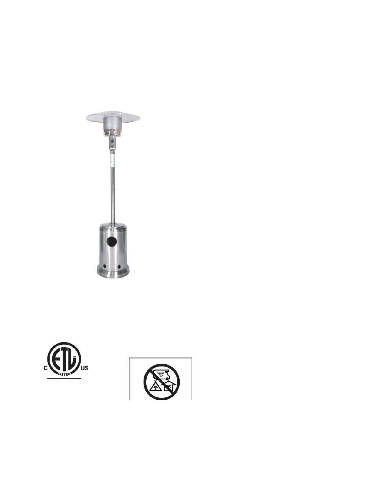
Patio Heater
DANGER
If you smell gas:
1. Shut off gas to the appliance.
2. Extinguish any open flame.
3. If odor continues, keep away from the appliance and
immediately call your gas supplier or fire department.
A WARNING
Do not store or use gasoline or other flammable vapors and
liquids in the vicinity of this or any other appliance. An LP-
cylinder not connected for use shall not be stored in the vicinity
of this or any other appliance.
WARNING
For outdoor use only,
INSTALLER:
Leave this manual with the appliance.
CONSUMER: Retain this manual for future reference.
WARNING!
Improper installation, adjustment, alteration, service or
maintenance can cause injury or property damage. Read the
owner's manual thoroughly before installing or servicing this
equipment. If the information in this manual is not followed
exactly, a fire or explosion may result causing property damage, personal injury or loss of life.
CARBON MONOXIDE HAZARD
This appliance can produce carbon monoxide which has no odor.
Using it in an enclosed space can kill you. Never use this appliance in an enclosed space such as a
camper, tent, car or home.
Owner's Manual
Before you assemble or operate this unit, please
carefully read this entire manual. Failure to do so
may result in a fire, explosion, injury or death.
WARNING
•The installation of this unit must adhere to
local codes or Propane Storage and Handling Code, CSAB149.2.
•THIS UNIT IS INTENDED FOR OUTDOOR USE ONLY! This product shall be used outdoors, in a
ventilated space and shall not be used in any enclosed area.
•This unit is to be used with propane gas only! (sold separately)
Intertek
5009770
DANGER

SAFETY INFORMATION
•Do not attach a remote gas supply to this unit.
•Only use propane gas for this unit.
•This unit is not intended for natural gas.
•Converting this unit to natural gas is dangerous and not recommended. The conversion of this unit will
void the manufacturer warranty.
•Do not use any solid fuel or charcoal for this unit.
•If the propane gas tank is leaking gas, you may hear, see, or smell a hiss. Do the following:
1. Disconnect the propane gas tank. 2. Do not attempt to fix the problem yourself. 3. Contact your gas
supplier or fire department for help.
•Applying too much propane may result in gas pooling and will not burn. Allow fresh air into the unit so
that the remaining gas may escape.
•Do not use a flame to check for gas leaks.
•The max. inlet supply pressure: max. Gas supply 11 in w.c. (2.74kPa)
•Use LP propane tanks with the following dimensions: diameter 12 in, height 18 in.
•You must use a propane tank that has a collar to protect the gas valve.
•Do not fill tank over 80 percent full.
•The tank system must be set up for vapor withdrawal.
•Discontinue use if any part of the propane tank is damaged. Rust and dents may be hazardous and should
be inspected by a gas supplier.
•Do not burn anything other than the provided materials for this patio heater.
•Do not operate unit until all parts are fully assembled.
•Do not paint or color any part of this heating unit.
•Unit may be hot while in use, do not attempt to move it while in use.
•Never leave this heating unit unattended while in use.
•This unit is not intended for cooking.
•Keep any flammable items away.
•Keep a safe distance to avoid burning skin or clothing.
•Do not sit or rest hands or feet on this heating unit.
•Never place hands or fingers on upper portion of this unit while in use.
•Keep all electrical cords and fuel supply hose away from heated surfaces.
•Combustible material should not be within 48 inches of the top of the unit, or within 48 inches around the
entire unit.
•Keep the appliance area clear and free from combustible material, gasoline and other flammable vapors
and liquids.
•If the flame goes out while burning, turn the gas valve off. Wait 5 minutes before repeating the initial
lighting procedure. Once you have a flame started, hold down the control knob for 1 minute.
•Do not add water into the unit.
•Do not operate unit if any part has been under water. Call a service technician to replace any damaged
parts should this occur.
•Do not disconnect any part while unit is in use.
•Do not store a spare propane tank on or near this unit.
•If the heating unit is indoors, detach the propane tank and leave outdoors.
•Do not operate on a boat or vehicle. This unit must be used on a flat surface and outdoors ONLY.
•Always remove protective cover before operating (if applicable).
•Check for leaks if the unit has not been used for a long period of time.
•Children should never operate this unit. Children must be supervised while near this unit.
•Keep gas tank at least 5 feet away from unit when lit. (if external tank)

•The maximum gas supply pressure is 250psi.
• All installation and repair should be done by a qualified professional. This unit should be inspected
annually and cleaned regularly.
•Inspect all elements of this heating unit before each use. If there is damage, the burner must be replaced.
•Be aware of the hazards of high temperatures and stay away from the unit to avoid any burns or injury.
•The gas supply tank should be constructed and marked with the specifications for the LP gas tanks of the
U.S. Department of Transportation or the National Standard of Canada CAN/CSA-B339, LP gas tanks,
spheres and tubes for Transportation of Dangerous Goods; and Commission.
•The LP gas tank must have a listed over-fill prevention device and a QCCI or Type I, (CGA791) LP gas
tank connection.
•This heating appliance should not be used on plastic or artificial wood decks.
•Children and adults should be alerted to the hazards of high surface temperatures and should stay away to
avoid burns or clothing ignition.
•Young children should be carefully supervised when they are in the area of the appliance.
• Clothing or other flammable materials should not be hung from the appliance or placed on or near
the appliance.
•Any guard or other protective device removed for servicing the appliance shall be replaced prior to
operating the appliance.
• Installation and repair should be done by a qualified service person. The appliance should be
inspected before use and at least annually by a qualified service person. More frequent cleaning may
be required as necessary. It is imperative that the control compartment, burners and circulating
airways of the appliance are kept clean.
Only use the regulator and hose assembly provided with this unit.
NOTE: You must follow all steps to properly assemble this heating item. Make sure the gas valve is turned
"OFF" before assembling. Do Not attempt to assemble without proper tools.

SAFETY INFORMATION
BE CAREFUL: WHEN CERTAIN MATERIALS OR
ITEMS ARE STORED ABOVE, BESIDE OR UNDER
THIS HEATER WHILE IN USE, THEY WILL BE
SUBJECT TO RADIANT HEAT AND COULD BE
SERIOUSLY DAMAGED.
Combustible materials should not be within 48 inches of the
top of the unit, or within 48 inches around the entire unit.
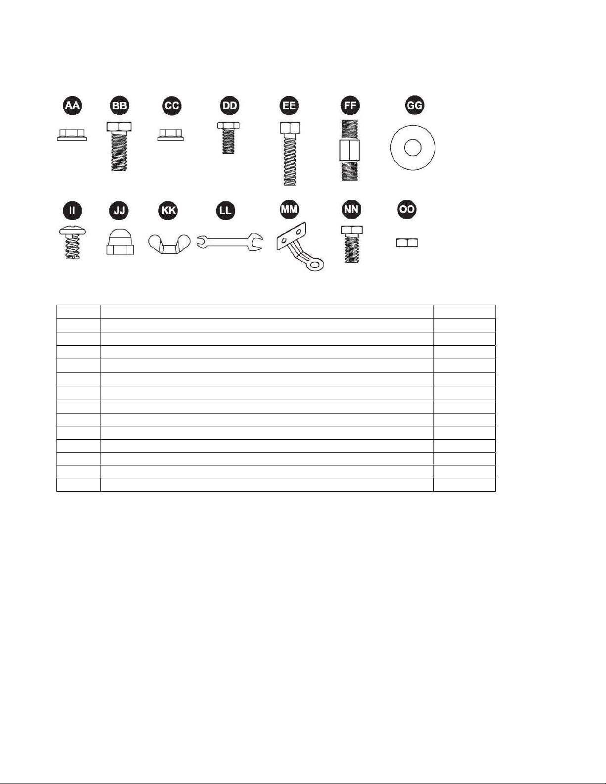
HARDWARE
Item
Description
Qty
AA
M8 Flange Nut (pre
-
assembled on part 1)
2
BB
Bolt M8x16 (2 pcs pre
-
assembled on part I)
5
CC
M6
Flange Nut
6
DD Stainless Steel Bolt (pre-assembled on part C) 4
EE Bolt M6x30 6
FF Reflector Spacer 3
GG Washer 9
II
Screw M6x10
9
JJ
Cap Nut
9
KK Wing Nut 3
LL Wrench 1
MM
Anchoring Arm
3
NN
Bolt M6x10
6
OO
M6Nut
6
Before beginning assembly of product, make sure all parts are present. Compare parts with package contents
list and hardware contents list. If any parts are missing or damaged, do not attempt to assemble the product.
Estimated Assembly Time: 30 minutes
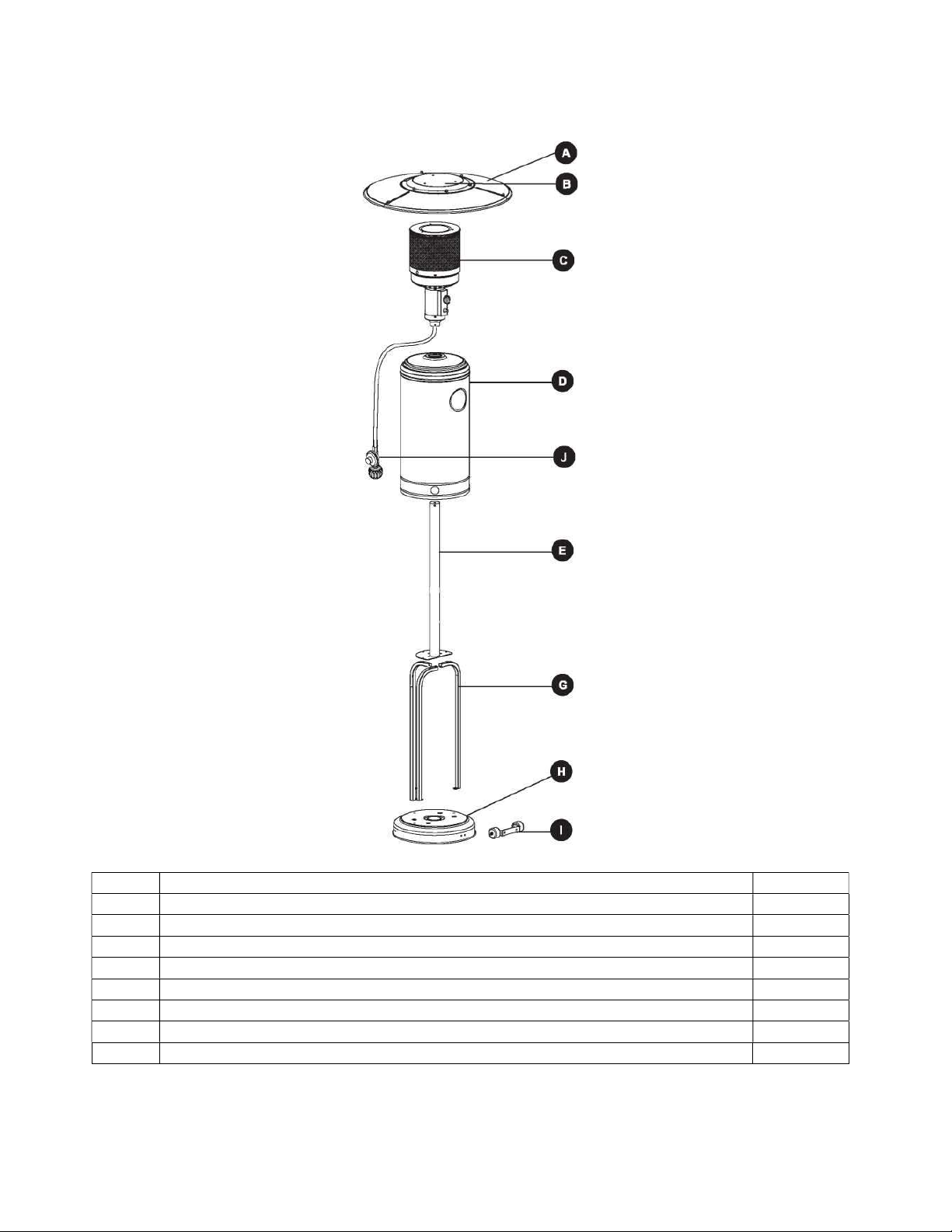
CONTENTS
Item
Descrip
tion
Qty
A
Reflector Panel
3
B Center Reflector 1
C
Burner Assembly
1
D
Tank Housing
1
E
Post
1
G
Support Bracket
3
H Base 1
I
Wheel Assembly
1
J Regulator 1

x
3
ASSEMBLY INSTRUCTIONS
STEP 1
Turn the base upside down, then attach wheel
assembly (I) to base (H) using 2pcs M8 flange nuts
(AA) and 2pcs bolts M8x16 (BB). Attach 3pcs
anchoring arm (MM) to base (H) using 6pcs M6 nuts
(OO) and 6pcs bolt M6x10 (NN).
Be sure that the wheel assembly is parallel to the base.
Tighten bolts securely.
Hardware Used
M8 Flange nut
Bolt M8x16
Anchoring Arm
Bolt M6x10
M6 Nut
STEP 2
Attach 3 pcs support brackets (G) to base (H)
using 3pcs bolts M8x16(BB).
Hardware Used
Bolt M8x16

ASSEMBLY INSTRUCTIONS
x
6
STEP 3
Attach post assembly to support brackets (G) using
6pcs bolts M6 X 30 (EE) and 6pcs M6 flange nuts
(CC). Tighten bolts securely.
Hardware Used
STEP 4
Load tank housing onto post, slide tank housing
down.
STEP 5
Remove the 4 pcs preassembled stainless steel bolts
(DD) from the burner assembly (C).
Insert the gas hose from the top end of the upper
post (E), then attach the burner assembly (C) to
upper post (E) using the four bolts removed at the
beginning of this step. Tighten bolts securely.
Hardware Used
Bolt M6x30
M6 Flange nut
Stainless steel bolt x4

ASSEMBLY INSTRUCTIONS
Hardware Used
Cap nut
Screw M6X 10
x
3
x
9
x
3
STEP 6
WARNING: Remove protective cover before
assembling.
Note: If necessary, for proper alignment of reflector
sections. Attach 3 pcs reflector panels (A) to center
Reflector (B) using 9 pcs Screws M6x10 (II) and 9
pcs cap nuts (JJ). Fully tighten all the screws.
STEP 7
Attach 3 pcs reflector spacers (FF) and 3 pcs
washers (GG) to burner assembly (C) firstly.
Tighten the reflector spacers. Slide 3pcs washers
(GG) over threaded end of spacer.
Attach the reflector assembly to the top of reflector
spacer (FF) using 3 pcs washers (GG) and 3 pcs
wing nuts (KK).
Hardware Used
Reflector spacer
Wing nut
Washer

ASSEMBLY INSTRUCTIONS
STEP 8
Place the propane gas tank (not included) on the base.
STEP 9
Turn the cylinder valve on the tank
clockwise to close the propane tank. Attach
the regulator (J) to the cylinder valve by
turning the regulator coupling nut clockwise.
Make sure it is fastened securely and tighten
connections by hand only.
OPERATION
Before performing a leak test, be sure that no sparks can occur and you are in a spacious outdoor area.
Connect the propane gas tank to the regulator and turn the valve on the unit to the "off position. Brush a soap
and water mixture on all connections. Turn the gas supply on; if bubbles occur on any connection there may
be a leak. If you smell gas or a leak is discovered turn the gas valve off, disconnect propane gas tank and do
not use the appliance until the leak is repaired.
Do not use the heating unit without inspecting the gas hose. If there are signs of wear or abrasion you must
replace the hose (if applicable).
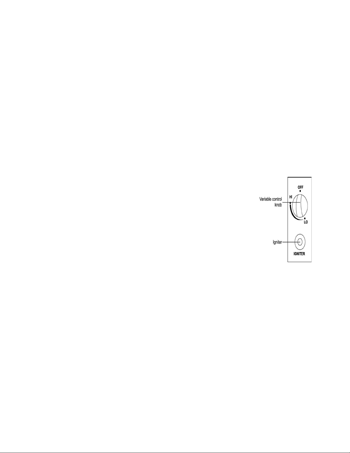
To Light
1. Turn on the valve on the gas supply cylinder.
2. Press and turn the variable control knob to the 'HI' position.
3. Press down the variable control knob and hold for 3-5 seconds.
5. If a new tank has just been connected, allow at least one minute or more for the air
in the gas pipeline to purge out.
6. The flame can be watched and checked from the viewing hole located on the base
of the burner.
7. Turn the variable control knob to the 'LO' position for 5 minutes or more before
turning the knob to desired temperature setting. If a small flame is needed, turn the
variable control knob to the 'LO' position.
8. If the burner flame goes out accidentally or it is blown out by wind, turn off the
heater and wait at least 5 minutes or more to let the gas dissipate before lighting
again to avoid possible gas explosion. Repeat steps 2 through 4.
When lit for the first time the heater may emit a slight odor and smoke. This is a normal and temporary
condition. Emitter screen will become a bright red due to the heat. The color is more visible at night. Flame
patterns should be a blue flame; these flames should not be yellow in color; indicating an obstruction of
airflow through the burners.
To Extinguish
1. Turn control knob clockwise to the "off" position.
2. Close the cylinder valve on the propane gas tank if you do not intend to use it for a long time.
MAINTENANCE
• Before performing any maintenance always disconnect propane gas tank.
• Keep the heating item free and clear from combustible materials.
• Visually inspect burner for obstructions and keep tank enclosure free and clear from debris.
• Use a soft brush to get rid of the mild stains, loose dirt and soil after the burner is completely cooled
down. Wipe down with a soft cloth.
• Harsh weather conditions may cause stubborn stains, discoloration and possibly rust pitting.
4. While holding down the variable control knob, press the igniter button several times until the
burner head fame ignites. Release the variable control knob 30 seconds after ignition.

• Permanent damage may occur if powder or solvent comes into contact with painted or plastic components
on this heating unit.
• Keep the heating unit stored away from direct sunlight.
• If storing this unit inside, disconnect the propane gas tank from the gas valve.
• Not using manufacturer approved or supplied parts/accessories may result in a defective condition and
void the warranty of this heating unit.
• Always place lid (if applicable) or protective cover on heating item when not in use.

TROUBLESHOOTING
Problem Cause Solution
The burner will not light.
The burner injector is clogged.
Clean the burner injector.
There is low gas supply pressure.
Call your ga
s supplier
The burner flame goes off
immediately after ignition.
There is low gas pressure. Call your gas supplier;
The ignition is delayed. The main burner carryover ports are
clogged.
Clean the main burner ports.
There is low gas pressure.
Call your
gas supplier.
The combustion on the burner is
inadequate.
There is not enough ain
Check the air
passageways and burners for dirt
and debris, and clean with compressed air
The burner flame is low. The supply hose is bent or twisted.
Straighten the hose an
d perform a leak test.
There is blockage in the burner injector.
Clean or replace the burner injector
The emitter glows uneven.
There is blockage in the burner injector.
Clean or replace the burner injector
The base is not on a level surface. Place the heater on a level surface.
The gas pressure is low.
Replace the cylinder with a
new cylinder
There is slight smoke and odor during
initial operation.
This is residue from the manufacturing
process.
This will stop after approximately 30 minutes
of oper
ation.
There is thick black smoke. There is blockage in the burner; Turn off the heater and let it cool.
Remove the blockage and clean the inside and
outside of the burner:
The heater produces a whistling noise
when the burner is lit
Air passageways are blocked.
Check the minimum installation clearances
and air passageways for debris.
There is air in the gas line. Operate the burner until the air is completely
purged.
The heater produces a clicking noise
just after the burner is lit or turned off.
The metal is expanding and contracting.
This is common with heaters. If noise is
excessive, contact a qualified service person.
There is a gas odor even when the
control knob is in the OFF position.
There is a gas leak.
Locate and correct the leak immediately
The gas control is defective. Replace the gas control.
There is a gas odor during
combustion.
There is foreign matter in the gas or on the
burner ports.
Check the gas passageway and burner
The heater is burning vapors from paint or
impurities in the air
Stop storing and using odor causing products
near the heater
There is gas leaking from the regulator and
hose connection, the valve and pipe
connections, and the pipes.
Locate and correct the leaks or contact your
gas supplier.
There is carbon build-up. There is dirt or film on the reflector and
flame screen.
Clean the reflector and flame screen.
This manual suits for next models
1
Table of contents
Other Flash Furniture Patio Heater manuals

Popular Patio Heater manuals by other brands


EUROM
EUROM Q-time 2000S instruction manual

Well
Well HTR-IR-PW2000-WL instruction manual

Jumbo
Jumbo Ayce GPH 2000 MACAO Original instructions

Outdoor Order
Outdoor Order HALO MTC-HALO-GM-LP user manual

Silverline
Silverline COMFORT 1200 DIGITAL IPX4 manual

Herschel
Herschel FLORIDA 2000 Watts Installation & operating instructions

Backyard Pro
Backyard Pro PH08-SB quick start guide

Jumbuck
Jumbuck JDS06 manual

Heat Outdoors
Heat Outdoors UMBRA Tulip Safety instructions and operation manual

Perel
Perel EPATH2 user manual

Barbecook
Barbecook Infra Nomad CLASSIC User manual and assembly instructions

Royal garden
Royal garden TM21PATHTRSS1 Assembly instructions