Jumbuck JDS06 User manual

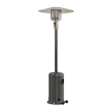
Outdoor Patio Heater
Portable heater with gas bottle housing.
Wheels for easy mobility.
Stainless Steel Burner head.
Operates on Propane Gas.
38.5MJ/h Output.
Flame failure & tip over safety switch.
9Kg gas bottle fits housing.
Powder coated steel.
Colour: Charcoal.
12 month warranty.
t
t
t
t
t
t
t
t
t
t
Please retain this manual for reference
The Australian
Gas Association

GAS LEAK TEST
Gas connections on the heater are leak tested at the factory prior to shipment. A complete gas
tightness check must be performed due to possible mishandling in shipment or excessive pressure
being applied to the heater gas connections.
1.Make a soap solution of one part liquid detergent and one part water.
Make sure the control knob on the heater is off and the gas valve on the cylinder is off before
mixing the soapy solution.
2.Turn on the gas bottle.
3. Apply the soap solution to the gas connections using a soft bristle brush.
Soap bubbles will appear
if there is a gas leak.
In case of a leak, turn off
the gas supply. Tighen any
leaking fittings, then turn the
gas supply on and re-check.
If there is a leak anywhere
on the gas cylinder, do not
use the cylinder. Locate the
leaking cylinder outdoors
away from sources of
ignition, then contact your
local gas authority or
cylinder exchange provider
to arrange disposal.
Warning:
Do not operate the appliance until all gas leaks have been rectified.
Never leak test while smoking.
+++
+
+
+
Regulator / Cylinder
Hose / Regulator
Detergent

TABLE OF CONTENTS
Caution ………………………………………………………. 1
Heater Stand and Location ………………………………… 2
Gas Requirements ………………………………………….. 4
Leakage Test …………………………………………… ….. 4
Operation and Storage ……………………………………... 5
Cleaning and Care ………………………………………….. 6
Parts and Specifications ..………………………………….. 6
Assembly Parts and Procedures ………………………….. 7
Trouble Shooting ………………………………………........ 11
i

CAUTION
PLEASE READ CAREFULLY THE FOLLOWING SAFETY GUIDELINES BEFORE OPERATION.
Do not use the patio heater for indoors, as it may cause personal injury or property damage.
Do not place articles on or against this appliance
Do not use or store flammable materials near this appliance
Do not spray aerosols in the vicinity of this appliance while it is in operation
This outdoor heater is not intended to be installed on recreational vehicles and/or boats.
Repair should be done by a qualified service person.
Improper installation, adjustment, alteration can cause personal injury or property damage.
Do not attempt to alter the unit in any manner.
Never replace or substitute the regulator with any regulator other than the factory-suggested
replacement.
Do not store or use gasoline or other flammable vapors or liquids in the heater unit.
All leak tests should be done with a soap solution. Never use an open flame to check for leaks.
Do not use the heater until all connections have been leak tested.
Turn off the gas valve immediately if smell of gas is detected.
Do not transport heater while it’s operating.
Do not move the heater after it has been turned off until the temperature has cooled down.
Keep the ventilation opening of the cylinder enclosure free and clear of debris.
Do not paint the radiant screen, control panel or top canopy reflector.
Control compartment, burner and circulation air passageways of the heater must be kept clean.
More frequent cleaning may be required as necessary.
The whole gas system, hose, regulator, pilot or burner should be inspected for leaks or damage before
use, and at least annually by a qualified service person.
Adults and children should stay away from high temperature surface to avoid burns or clothing ignition.
Children should be carefully supervised when they are in the area of the heater.
Clothing or other flammable materials should not be hung on the heater or placed on or near the heater.
The gas cylinder should be turned off when the heater is not in use.
Check the heater immediately if any of the following occurs:
-the heater does not reach temperature.
-the burner makes popping noise during use ( a slight noise is normal when the burner is
extinguished ).
-smell of gas in conjunction with extreme yellow tipping of the burner flames.
The regulator/hose assembly must be located out of pathways where people may trip over it or in area where the
hose will not be subject to accidental damage.
Any guard or other protective device removed for servicing the heater must be replaced before
operating the heater.
This appliance shall not be installed or used indoors
lf there is any evidence of excessive abrasion or wear, Or if the hose assembly is damaged do not operate the
appliance until a replacement hose assembly has been obtained from your authorized service provider Ensure that
the replacement hose assembly is as specified by the manufacturer.
Due to radiant heat Certain materials or items may be seriously damaged if stored under or near this
appliance while it is in operation.
Remove any packaging/transit protection prior to operating this appliance.
-1-
This patio heater is not for commercial use.

610mm
460mm

-3-
Both ends open
Open side at least
25% of total wall area
30 percent or more in total
of the remaining wall area
is open and unrestricted

-4-
GAS REQUIREMENTS
LEAKAGE TEST
•Refer to the gas type label for confirmation of the gas type to be used with your appliance..
•Use only the pressure regulator and hose assembly supplied with this appliance.
•A dented, rusted or damaged gas cylinder may be hazardous and should be checked by your cylinder
supplier. Never use a gas cylinder with a damaged valve connection.
•Never connect an unregulated gas cylinder to the heater.
•This appliance is NOT suitable for use with a fixed gas supply system. Use ONLY a 9kg gas cylinder.
•Gas connections on the heater are leak tested at the factory prior to shipment. A complete gas tightness
check must be performed due to possible mishandling in shipment or excessive pressure being applied to
the heater.
•Make a soap solution of one part liquid detergent and one part water.
•The soap solution can be applied with a spray bottle, brush or rag. Soap bubbles will appear in case of a
leak.
•The heater must be checked with a full cylinder.
•Make sure the safety control valve is in the OFF position.
•Apply the soap solution to the gas connections.
•Turn the gas supply ON.
•In case of a leak, turn off the gas supply. Tighten any leaking fittings, then turn the gas supply on and re-
check.
•Do not operate the appliance until all gas leaks have been rectified.
•Never leak test while smoking.
Open side at least
25% of total wall area 30 percent or more in total
of the remaining wall area
is open and unrestricted

-5-
OPERATION AND STORAGE
TO TURN ON THE HEATER
1. Turn on the valve on the gas cylinder.
2. Press and turn the control knob to HI position
(anti-clockwise 90°).
3. Press and hold down the control knob, at the same time
repeatedly pressing the igniter button until the burner is ignited.
Release the control knob 10 seconds after the ignition, at which
time the burner should remain alight.
4. Turn the control knob to LO and leave it there for
5 minutes or more before turning the knob to the
desired temperature setting.
5. If the burner fails to light or goes out turn the control knob to
the "OFF" position. Wait at least 5 minutes to allow any gas
to dissipate, and repeat steps 2 - 4.
6. If still unable to light the burner turn the control knob to the "OFF"
position, turn off the valve on the gas cylinder, disconnect and
remove the gas cylinder and return the heater to the place of
purchase for a replacement.
TO TURN OFF THE HEATER
1. Turn the control knob to HI position.
2. Press and turn the control knob to OFF position.
3. Turn off the valve on the gas cylinder.
Storage
1. Always close the gas valve of the gas cylinder after use or in case of a disturbance.
2. Disconnect the regulator from the gas cylinder valve.
3. Check the tightness of the gas valve for damage. If you suspect damage, have it changed
by your gas dealer.
4. Never store liquid gas cylinder in a sub-terrain, or at places without adequate air ventilation.
5. There is no limitation on the storage of appliances indoors provided that the cylinder is removed
from the appliance; and
6. Storage of an appliance indoors with the cylinder attached is only permitted if the size of the
cylinder complies with AS/NZS 1596; otherwise cylinders must be stored outdoors in a
well-ventilated area and out of reach of children.

CLEANING AND CARE
Wipe off powder coated surfaces with soft, moist rag. Do not clean heater with cleaners that
are combustible or corrosive.
Remove debris from the burner to keep it clean and safe for use.
Cover the burner unit with the optional protective cover when the heater is not in use.
PARTS AND SPECIFICATIONS
-6-
2020 mm
620 mm
705 mm
460 mm
Reflector
Flame screen
Burner base
Air admittance fence
Gas valve controller
Base of control housing
Upper main pole
Tank housing
Support legs
Stand
Lower main pole

JDS06
4 pcs 3/16'' screw for 2pcs main pole
6 M6 wing nut and
30
JDS06
screw caps
380 800
13.2
202
705
M6
1.80 mm

-8-
ASSEMBLY PROCEDURES
STEP 2
2-1. Remove white cap from the base by pulling on the tab of the cap.
2-3. Replace white cap and ensure it is secure.
STEP 1
Use 2pcs M8X15mm bolts and M8 nuts to connect the bracket with
wheels to the base. Then fasten them.
2-2. FILL WITH FINE GRADE SAND. AFTER FULL WITH SAND - TOP
UP WITH WATER. (This sand can be purchased from most hardware
stores)
STEP 3
3-1. Put the 3 pcs support legs oneach position on the base as
shown in the picture.
3-2. Use 3 pcs M8 x 16 mm bolts to join the support legs and stand.
STEP 1
Base
Wheel
STEP 3
Bolt
Stand
Square metal
support legs
STEP 2

-9-
STEP 6
6-2.
6-1.
Take the burner head with hose already attached and feed
the hose down into the main pole
Attach the top section of the main pole with 4pcs 3/16” screws.
.
6-3. Fix the completed burner unit to the main pole by 4pcs M6x10mm
bolts; ensure "Heater Operation Label" faces the same way
as the gas controls.
6-4.
STEP 4
4-1. Assemble the bottom section of the main pole on top of 3pcs support legs.
4-2. Use 6 pcs M6 x 30 mm bolts and nuts to connect the main pole to the
3 pcs support legs .Tighten the bolts and nuts. Main pole
Nut
STEP 4
Bolt
Bolt
STEP 5
STEP 6
Tank housing
STEP5
Place the tankhousingon thestand. If your tank housing has a protective
plastic coating, please remove before operating the heater.
Attach the supplied regulator to the hose end and
tighten the connection with 2 spanners.

-10-
STEP 9
Fasten the reflector with 3 pcs washers and 3 pcs M6 mm wing nuts.
STEP 8
Assemble the 4 piece reflector according to the following sketch.
If your reflector has a protective plastic coating, please remove
before operating the heater.
7-1. Check whether the connection of vertical post and burner are
assembled according to instructions, and all bolts and nuts are
tightened.
7-2. Screw 3 reflector spacers on to burner.
7-3. Put washer Ø6 mm on each reflector spacer.
STEP 7 STEP 7
STEP 8
STEP 9
Reflector flat washer
Reflector
Nut

-11-
STEP 10
STEP 10
10-1. Bring up the tank housing and rest it on the post plate.
10-2. Connect the regulator to the gas cylinder and tighten it with adjustable
wrench.Conduct a gas leakage test as described earlier in this manual.
10-3. Put gas cylinder on the stand.
Trouble Shooting
Problem Possible cause
What you can do
(if these do not work,
contact an authorised
technician)
What ONLY an
authorised
service
technician can
do
Burner will not light Gas valve may be OFF
Tank fuel empty
Opening blocked
Loose connections
Low gas pressure
Thermocouple bad
Not in correct location
Turn the gas valve ON
Check all fittings
Replace cylinder with a new
cylinder
Refill gas cylinder
Refill gas cylinder
Remove and clean
Replace thermocouple
Burner will not stay
on Loose connections
Thermocouple bad
Gas leak in line
Lack of fuel pressure
Tank near empty
Tighten connections
Check connections Clean dirty area
Replace
thermocouple
Burner flame is low Supply hose is bent or
twisted Straighten hose and perform leak
test on hose
Emitter glows
uneven Low gas pressure
Base is not on a level
surface
Replace cylinder with a new
cylinder
Place heater on a level surface
Thick black smoke Blockage in burner Turnoff the heater and let it cool. Remove blockage and
clear burner inside
and outside
Carbon build-up l Dirt or film on reflector
and flame screen Clean reflector and flame screen
Regulator
Gas cylinder

Product Warranty
Any claim under this warranty must be made within (12) months from the date of purchase of the
product. To make a claim under the warranty, take the product (with proof of purchase) to any
Bunnings store. (see www.bunnings.com.au for store locations) or contact our service agent on
number below.
Bunnings Group Ltd bears reasonable, direct, expenses of claiming under the warranty. You may
submit details and proof to Bunnings Group Ltd for consideration.
The warranty covers manufacturer defects in materials, workmanship and finish under normal use.
This warranty is provided in addition to other rights and remedies you may have under law: our
goods come with guarantees which cannot be exluded under the Australian Consumer Law. You
are entitled to replacement or refund for a major failure and to have the goods repaired or replaced
if the goods fail to be of acceptable quality.
The warranty excludes damage resulting from product misuse, or product neglect. The warranty
covers domestic use only and does not apply to commercial applications.
This Warranty is given by Bunnings Group Ltd ABN 26 008 672 179, Postal address: 16-18 Cato
For after market service please call: 1300 793 978
Table of contents
Popular Patio Heater manuals by other brands

Silverline
Silverline COMFORT C-Wave 900 IPX4 manual

Outdoor Leisure
Outdoor Leisure TD100A owner's manual

Paramount Fitness
Paramount Fitness LIP 10 A TGG instruction manual

Blue Sky Outdoor Living
Blue Sky Outdoor Living WBFP31SQ-GF owner's manual

Heat Outdoors
Heat Outdoors SHADOWFB2400 Safety instructions and operation manual

Blumfeldt
Blumfeldt Rising Sun manual