manuals.online logo
Brands
  1. Home
  2. •
  3. Brands
  4. •
  5. Fleck
  6. •
  7. Water Dispenser
  8. •
  9. Fleck 5600 Econominder User manual

Fleck 5600 Econominder User manual

I came that they may have life and have it abundantly. John 10:10
Providing the quality water you deserve at a price you can a!ord!
II nn ss tt aa ll ll aa tt ii oo nn II nn ss tt rr uu cc tt ii oo nn ss ff oo rr WW aa tt ee rr SS oo ff tt ee nn ee rr ss ww ii tt hh FF ll ee cc kk 55 66 00 00 aa nn dd
55 66 00 00 SS XX TT
Covers standard water softeners using a separate
brine tank.
TT HH AA NN KK YY OO UU
Thank you for purchasing a new Water Softener from Abundant Flow Water. We appreciate the
opportunity you have given us to provide you with better water. We are committed to providing the
best customer experience possible and have provided these installation instructions to make things as
simple as possible. If you have read through these entire instructions and FAQ section and still have
questions feel free to contact us for further help. Our o"ce hours are Monday-Friday 8:00 AM - 5:00 PM
CT, and you can call us at 785-735-9769.
BB EE FF OO RR EE YY OO UU BB EE GG I I NN
** ! ! **
BB aa s s i i c c pp l l uu mm bb i i nn gg s s k k i i l l l l s s a a r r ee r r ee qq uu i i r r ee dd f f oo r r i i nn s s t t a a l l l l aa t t i i oo nn . . I I f f y y oo uu a a r r ee uu nn s s uu r r ee oo f f y y oo uu r r aa bb i i l l i i t t iieess ttoo iinnss ttaallll
tt hh ee ss yy ss tt ee mm uu ss i i nn gg tt hh ee ss ee i i nn tt rr uu cc tt i i oo nn ss pp l l ee aa ss ee hh i i rr ee aa qq uu aa ll i i ## ee dd pp l l uu mm bb ee rr . .
**!!**
** ! ! **
RR ee a a dd t t hh r r oo uu gg hh y y oo uu r r pp a a r r t t s s l l i i s s t t aa nn dd v v ee r r i i f f y y aa l l l l c c oo mm pp oo nn ee nn t t s s aa r r ee aa c c c c oo uu nn t t ee dd f f oo r r aa nn dd i i nn gg oo oo dd
cc oo nn dd i i tt i i oo nn BB EE FF OO RR EE ss cc hh ee dd uu l l i i nn gg aa pp l l uu mm bb ee rr . .
**!!**
** ! ! **
PP l l ee aa s s ee r r ee aa dd t t hh r r oo uu gg hh t t hh ee ee nn t t i i r r ee i i nn s s t t r r uu c c t t i i oo nn mm aa nn uu aa l l c c aa r r ee f f uu l l l l yy . . I I f f hh i i r r i i nn gg aa pp l l uu mm bb ee r r ee nn s s uu rr ee tt hh ee yy
hh aa vv ee aa cc oo pp yy bb ee f f oo r r ee t t hh ee yy ss t t aa r r t t . .
**!!**
** ! ! **
MM o o s s t t c c o o mm mm o o n n q q u u e e s s t t i i o o n n s s a a r r e e a a n n s s ww e e r r e e d d i i n n t t h h e e i i n n s s t t r r u u c c t t i i o o n n s s o o r r F F A A QQ s s e e c c t t i i o o n n . . I I f f y y o o u u h h a a v v e e r r e e aa dd
bb oo t t hh oo f f t t hh oo s s ee aa nn dd s s t t i i l l l l hh aa vv ee qq uu ee s s t t i i oo nn s s yy oo uu mm aa yy c c oo nn t t aa c c t t uu s s f f oo r r f f uu r r t t hh ee r r hh ee l l pp . .
**!!**
** ! ! **
PP l l uu mm bb i i nn gg r r ee l l aa t t ee dd qq uu ee s s t t i i oo nn s s nn ee ee dd t t oo bb ee dd i i r r ee c c t t ee dd t t oo aa l l oo c c aa l l l l yy qq uu aa l l i i ## ee dd pp l l uu mm bb ee r r . . WW ee aa r r ee nn oo t t
pp l l uu mm bb ee r r s s aa nn dd aa nn yy pp l l uu mm bb i i nn gg qq uu ee s s t t i i oo nn s s ww ee r r ee c c ee i i vv ee ww i i l l l l nn oo t t bb ee aa nn s s ww ee r r ee dd . .
**!!**
SS YY SS TT EE MM RR EE QQ UU I I RR EE MM EE NN TT SS
Your chosen installation location and water supply must meet ALL of the following requirements:
20-90 PSI (1.38-6.20BAR)
34-110°F (1.1-43.3°C)
1 of 19
System must be protected from freezing
Firm level surface AFTER the pressure tank
3-prong, 120V outlet within 5 ft. (1.5 m) of the control head with constant
power. GFCI outlet is recommended. Use of an extension cords is not
recommended.
A 1.5 inch standpipe, sump pit, or outside drain.
** **
PP l l ee aa s s ee nn oo t t ee : :
****
The drain
line is pressurized and can be ran vertically if necessary.
11
——
VV EE RR I I FF YY SS YY SS TT EE MM II NN VV E E NN T T OO RR Y Y
Use the following table to help verify the parts that are included with your system and verify that they
are all accounted for. Inspect all parts for damage and report any damage immediately. Damage claims
must be made within 30 days of delivery to be eligible for replacement.
A tall slender tank 44–65 inches in height with
an opening on the top. Tanks that are 14 inches
or larger may have a gray threaded adapter to
reduce tank opening to match control head.
PP oo l l yy gg l l aa s s s s TT aa nn kk
A tall pipe that runs from the bottom of the
tank to the control valve. One end has a basket
(basket design varies) and it usually ships inside
the tank.
RR i i s s ee r r / / DD i i s s t t r r i i bb uu t t oo r r TT uu bb ee
2 of 19
Screws on top of the tank and controls the
water $ow and regeneration cycles. Digital SXT
has LCD panel. The mechanical has control
knobs.
** **
PP l l ee aa s s ee nn oo t t ee : :
****
Some SXT systems may have
labels referring to the older SE model number.
This is an internal designation and does NOT
indicate that you received an SE controller.
CC oo nn t t r r oo l l HH ee aa dd
A large plastic tank (round OR
square/rectangular) similar to a trash can. Inside
the tank is the brine well—a small cylinder
about 4 inches (10.1 cm) in diameter—which
contains the saftey $oat. The brine tank holds
the salt (
****
nn oo t t i i nn cc l l uu dd ee dd
****
) used for
regeneration. There will also be an over$ow
#tting and tubing. Some systems may have a salt
grid—a plastic grid on the bottom of the tank—
but most do not as they are not needed when
using pelleted salt as recommended. This tank
holds the salt,
** ! ! **
DD OO NN OO T T l l o o a a d d t t h h e e r r e e s s i i n n i i nn
bb r r i i nn ee t t aa nn kk . .
**!!**
BB r r i i nn ee TT aa nn k k
Small rocks or pebbles to promote water
distribution. Most systems use standard gravel,
but very large systems will use the denser
garnet gravel.
** ! ! **
GG r r a a v v ee l l gg oo ee s s i i nn ## r r s s t t
**!!**
, at
the bottom of polyglass tank.
GG r r a a v v ee l l / / gg a a r r nn e e t t
3 of 19
Bag(s) of material placed in the polyglass tank
that does the actual treatment of the water.
** **
CC oo l l oo r r oo f f r r ee s s i i nn mm aa y y v v aa r r y y
****
** **
PP l l ee aa s s ee NN oo t t ee : :
****
Depending on system size
you may receive more than one package of resin
packaged di!erently. This is normal. The system
is sent with the required amount of resin and
** ! ! **
aa l l l l r r ee ss i i nn ww i i l l l l bb ee uu ss ee dd . .
**!!**
RR ee s s i i nn
Depending on your order your system will have
either a single piece stainless steel bypass or a
two part plastic bypass with yoke connection.
This is what connects to your control head and
provides standard #tting connections to hook
up to your plumbing.
BB y y pp a a s s s s VV aa l l v v ee
The $ow meter connects the control head and
the bypass valve and it measures the water $ow
to initiate regeneration on demand. Includes
O-rings (already attached) to seal the
connection and screws and clips to secure the
connection. Typically connected to the control
head when received.
MM e e t t e e r r A A s s s s e e mm b b l l y y
4 of 19
Tubing and #ttings used to connect the control
head to the brine tank. Tubing is usually inside
the brine tank, the #ttings are usually in a small
bag, either with the tubing, with the
instructions, or with the control head. Fittings
include the brass brine nut, ferrule, insert, and
screen.
BB r r i i nn ee CC oo nn nn ee c c t t i i oo nn PP aa r r t t s s
Fitting(s) that connect the control head to the
drain line (not supplied). Depending on the
system ordered there are multiple options, and
the pictures shown are common examples but
actual #tting may vary.
DD r r a a i i n n F F i i t t t t i i n n g g
The funnel is a complementary item included
with some systems to help #ll the polyglass tank
with the resin. If your system does not include
one, a blender pitcher with the blade assembly
removed will screw onto the tank and work well.
FF uu nn nn ee l l
Depending on system size you can see what tank size and resin amounts you will receive:
5 of 19
IImmgg%%
11
%%--%%
TT aa nn kk && RR i i s s ee r r
TT aa nn kk SS i i zz ee aa nn dd RR ee ss i i nn QQ t t yy
SS t t aa nn dd aa r r dd
CC aa pp aa c c i i t t y y
11 66 kk
22 44 kk
33 22 kk
44 88 kk
66 44 kk
88 00 kk
99 66 kk
11 11 00 kk
TT aa nn kk ( ( i i nn
iinncchheess ))
8 x 44
8 x 44
9 x 48
10 x 54
12 x 48
OR 12 x
52
13 x 54
14 x 65
14 x 65
GG r r a a v v ee l l
10 lb
10 lb
12 lb
16 lb
20 lb
35 lb
50 lb
50 lb
RR ee s s i i nn
0.5 ft³
0.75 ft³
1 ft³
1.5 ft³
2 ft³
2.5 ft³
3 ft³
3.5 ft³
On systems shipped by truck the resin may be preloaded
BB ee f f oo r r ee y y oo uu s s t t a a r r t t pp l l uu mm bb i i nn gg
22
——
PP RR EE -- II NN SS TTAA LL LL AATT II OO NN PP RR EE PP EE RR AA TT I I OO NN
** **
MM o o n n e e y y - - s s a a v v i i n n g g t t i i p p : :
****
If hiring a plumber to do the installation you can save some money by
preparing the tank ahead of time. This cuts down on the time the plumber has to spend and doing so is
simple enough that most people can accomplish it in less than an hour.
22
..
11
——
VV ee r r i i f f y y r r i i s s ee r r t t uu bb ee s s i i z z i i nn gg
** ! ! **
VV ee r r i i f f y y t t hh ee r r i i s s ee r r t t uu bb ee ## t t s s a a nn dd s s ee a a l l s s i i nn t t oo t t hh ee c c oo nn t t r r oo l l hh ee a a dd . .
**!!**
.
A mismatched riser tube will prevent proper treatment, and it is
much easier to correct the problem before the resin is loaded. The
riser tube sits in an indentation centered in the bottom of the tank.
With the riser tube properly positioned, ensure that it is within 1/3
inch (8 mm) above or below the lip of the tank. If it is not contact us
for help correcting the problem.
22
..
22
——
FF i i l l l l t t aa nn kk pp aa r r t t i i aa l l l l yy ww i i t t hh ww aa t t ee r r
** **
OO p p t t i i o o n n a a l l
****
This optional step will help bu!er the resin as it is poured in and will also help minimize air bubbles
upon initial startup. Simply pour water into the tank until it is 1/4 - 1/3 #lled with water.
22
..
33
——
LL oo aa dd r r ee ss i i nn aa nn dd gg r r aa vv ee l l ——
**!!**
gg r r aa vv ee l l gg oo ee s s i i nn ## r r s s t t
**!!**
6 of 19
IImmgg%%
22
%%--%%
TT aa nn kk ww i i t t hh FF uu nn nn ee l l
IImmgg%%
33
%%--%%
TT aa nn kk OO - - r r i i nn gg
IImmgg%%
44
%%--%%
PP i i l l oo t t OO - - r r i i nn gg
** ! ! **
TT hh ee r r ee s s i i nn gg oo ee ss i i nn t t hh ee pp oo l l yy gg l l aa s s s s t t aa nn kk , , DD OO NN OO TT l l oo aa dd t t hh ee r r ee s s i i nn i i nn bb r r i i nn ee t t aa nn kk
**!!**
** **
MM a a k k e e s s u u r r e e t t o o c c o o v v e e r r t t h h e e o o p p e e n n i i n n g g o o f f t t h h e e r r i i s s e e r r t t u u b b e e
****
. Simply
put something over the end of the tube such as a piece of tape, to
prevent anything from falling into the riser tube.
** ! ! **
II ff yy oo uu hh aa vv ee gg rr aa vv ee ll ww ii tt hh yy oo uu rr ss yy ss tt ee mm ii tt ww ii ll ll gg oo ii nn ## rr ss tt !!
**!!**
Make sure to empty all boxes to verify it is not in the bottom of the
tank box or in a box with the resin.
When #lling the tank, do so slowly and ensure the riser tube stays
correctly positioned and centered in the tank. If you have more than
one bag of resin, after gravel the order does not matter and
** **
aa l l l l
oo f f i i t t s s hh oo uu l l dd bb ee uu s s ee dd
****
. Once all the resin is loaded the tank will
not be completely full, this is normal.
22
..
44
——
FF i i nn i i ss hh ## l l l l i i nn gg t t aa nn kk ww i i t t hh ww aa t t ee r r
** **
OO p p t t i i o o n n a a l l
****
Once the resin is loaded you may #nish #lling the tank with water. This can help reduce air bubbles and
ease initial startup.
33
——
AA TT TT AA CC HH TT HH EE CC OO NN T T R R OO L L HH EE AA DD
33
..
11
——
LL uu bb r r i i cc aa t t ee tt hh ee OO - - rr i i nn gg ss
** ! ! **
DD OO NN OO T T u u s s e e VV a a s s e e l l i i n n e e
**!!**
The tank O-ring—
II mm gg %%
33
—seals
the control valve to the tank,
and the pilot O-ring—
II mm gg %%
44
—seals around the riser
tube. Verify they are present and
free from nicks or kinks. Use a
silicon lubricant or vegetable oil
to both O-rings.
** ! ! **
DD OO NN OO T T u u s s e e
pp ee t t r r oo l l ee uu mm bb aa s s ee dd l l uu bb r r i i c c aa nn t t s s ! !
** ! ! **
** **
PP l l ee aa s s ee nn oo t t ee t t hh aa t t t t hh ee
pp i i l l oo t t OO - - r r i i nn gg i i s s uu pp i i nn s s i i dd ee t t hh ee
cc oo nn tt rr oo l l hh ee aa dd aa nn dd yy oo uu ww i i l l l l
uu s s uu aa l l l l yy hh aa vv ee t t oo r r ee aa cc hh uu pp i i nn ss i i dd ee t t oo f f ee ee l l i i t t . .
****
It is very secure inside the head and almost impossible for
it to come out. It is also a good idea to verify that the riser tube #ts snugly into the pilot hole and that
the O-ring seals around it.
33
..
22
——
II nn ss pp ee cc tt aa nn dd ii nn ss tt aa ll ll tt oo pp dd ii ss tt rr ii bb uu tt oo rr bb aa ss kk ee tt ii ff aa pp pp ll ii cc aa bb ll ee
7 of 19
IImmgg%%
55
%%--%%
TT oo pp DD i i s s t t r r i i bb uu t t oo r r BB aa s s kk ee t t
IImmgg%%
66
%%--%%
AA t t t t a a c c hh ee dd TT oo pp DD i i s s t t r r i i bb uu t t oo r r BB a a s s k k ee t t
IImmgg%%
77
%%--%%
UU nn a a s s s s e e mm bb l l e e d d BB r r i i nn e e T T a a n n k k
IImmgg%%
88
%%--%%
AA s s s s ee mm bb l l ee dd BB r r i i nn ee TT a a nn k k
Depending on system
con#guration your system may
include a top distributor
basket—
II mm gg %%
55
. If your system
includes one it is recommended
that you use it. If you do not
have one then it is not needed. If
you do have one the larger end
will #t inside the bottom of your
control valve, with the smaller
end sliding over the riser tube
pointing down into the tank—
II mm gg %%
66
. Please note that locking tabs hold it in place so a fair amount of force is needed to install or
remove it.
33
..
33
——
SS cc r r ee ww oo nn cc oo nn tt r r oo l l hh ee aa dd
** ! ! **
hh aa nn dd t t i i gg hh t t oo nn l l yy
**!!**
** ! ! **
DD OO NN OO T T a a p p p p l l y y a a n n y y t t h h i i n n g g ( ( p p i i pp e e d d o o pp e e , , p p l l uu mm bb e e r r s s p p a a s s t t e e , , T T e e $$ o o n n t t a a pp e e , , e e t t c c . . ) ) t t oo t t h h e e t t h h r r e e a a d d s s o o n n tthhee
cc oo nn tt rr oo l l hh ee aa dd oo rr tt hh ee rr ee ss i i nn tt aa nn kk ! !
**!!**
Ensure the riser tube slips inside the pilot opening in the bottom of the head. Screw the head down
onto the resin tank until solid contact is made between the tank and O-ring, then tighten about another
1/4–1/3 of a turn and STOP.
** **
DD o o n n o o t t o o v v e e r r t t i i g g h h t t e e n n t t h h e e c c o o n n t t r r o o l l h h e e a a d d a a s s t t h h i i s s c c a a n n c c a a u u s s e e d d a a mm a a g g e e . .
****
Once properly tightened down check to ensure the tank and control head meet evenly all the way
around.
44
——
PP RR EE PP AA RR EE AA NN DD CC OO NN NN E E C C T T BB RR I I NN EE TT AA NN KK
44
..
11
——
AA s s s s ee mm bb l l ee t t hh ee bb r r i i nn ee t t a a nn k k
The brine tank will come with
the brine well loose, either
inside the brine tank or in the
box with the brine tank—
II mm gg %%
77
.
You will use the over$ow #tting
to attach it in the side of the
brine tank, placing the over$ow
#tting through the lower hole on
the brine tank and securing it
through the brine well with the
nut—
II mm gg %%
88
. If you are having a
hard time #tting your hand
8 of 19
IImmgg%%
99
%%--%%
BB r r i i nn ee FF i i t t t t i i nn gg
IImmgg%%
11 00
%%--%%
BB r r i i nn ee LL i i nn ee FF i i t t t t i i nn gg s s
between the $oat and the brine well to secure the over$ow nut you can remove the $oat by removing
the nut that holds the $oat in place. Make sure to put it back when you are #nished.
44
..
22
——
UU s s e e 33 / / 8 8 i i nn c c hh l l i i nn e e t t oo c c oo n n nn e e c c t t bb r r i i n n e e t t a a n n k k t t oo c c oo n n t t r r oo l l hh e e a a dd
The brine line will connect from
the brine #tting on the control
head—
II mm gg %%
99
—to the #tting on
the $oat inside the brine tank.
To attach it to the $oat put the
tubing through the hole in the
brine tank and push the tubing
into the #tting until in stops,
then push a little harder to get it
to lock in place. To remove the
tubing, hold the collet ring that
sits around the tubing while
pulling the tubing out. The other end of the tubing will connect to the control head. Place the #ttings on
the tubing as shown—
II mm gg %%
11 00
—and connect it to the control head.
44
..
33
——
CC oo nn nn ee c c t t oo vv ee r r $$ oo ww t t oo $$ oo oo r r dd r r aa i i nn
** **
OO p p t t i i o o n n a a l l
****
If you have a $oor drain available you can connect the over$ow #tting to it using a $exible line.
** ! ! **
DD o o
nn oo t t cc oo nn nn ee cc t t t t hh ee oo vv ee r r $$ oo ww t t oo t t hh ee dd r r aa i i nn l l i i nn ee f f r r oo mm t t hh ee cc oo nn t t r r oo l l hh ee aa dd oo r r r r uu nn t t hh ee l l i i nn ee aa bb oo vv ee tthhee lleevveell ooff
tt hh ee oo vv ee rr $$ oo ww oo uu tt l l ee tt . .
**!!**
44
..
44
——
AA dd dd s s a a l l t t t t oo t t hh ee bb r r i i nn ee t t a a nn k k , ,
** **
ww a a t t e e r r i i s s n n o o t t n n e e c c e e s s s s a a r r y y
****
Add salt to the brine tank. We recommend high quality pelleted softener salt for the best results. You
will need to add at least one bag of salt and can #ll it up to the top of the brine well. Ensure there is salt
in the brine tank at all times.
** **
YY oo uu dd oo NN OO TT nn ee ee dd t t oo aa dd dd ww aa t t ee r r t t oo t t hh ee bb r r i i nn ee t t aa nn kk . .
****
The resin is
precharged and able to treat the water out of the box and the initial regeneration ran after installing
the system will place the initial volume of water in the brine tank.
55
——
SS EE TT UU PP CC OO NN T T R R OO L L HH EE AA DD
55
..
11
——
PP l l uu gg c c oo nn t t r r oo l l hh ee aa dd i i nn
Plug the control head into a quali#ng outlet as stated in the requirements section.
** **
PP l l ee aa s s ee NN oo t t ee : :
****
The contol head can be plugged in and operated without water, this will not damage the control head.
Once plugged in, verify the system is receiving power and ensure the outlet is not on a switch that
might get turned o!. On digital valves the display should light up and start $ashing a time, on
9 of 19
IImmgg%%
11 11
%%--%%
SS XX TT CC oo nn tt r r oo l l ss
mechanical valves you may hear a quiet hum of the motor or you may have to wait to see if the time dial
keeps track of time.
55
..
22
——
II nn ii tt aa ll vv aa ll vv ee ss ee tt uu pp
** **
II ff yy oo uu hh aa vv ee tt hh ee mm ee cc hh aa nn ii cc aa ll vv aa ll vv ee yy oo uu cc aa nn ss kk ii pp dd oo ww nn ttoo tt hh ee mm ee cc hh aa nn ii cc aa ll ss ee tt uu pp
****
To set the time of day press and
hold the up OR down arrow until
the service icon is replaced with
the programming icon. Use the
up and down arrows to set the
time of day (PM is indicated in
the upper right corner of the
screen). Hold the arrow down to
advance quickly through the
time. Once the time is set, press
the extra cycle button to save the
setting.
For initial programming ensure
the clock says 12:01 pm and the
parameter display is NOT shown.
Press and hold the up AND down
arrow buttons together for 5-10
seconds until the programming
icon appears and [DF] is shown in
the parameter code. Once each
setting has been entered, use the
extra cycle button to advance to
the next setting.
** **
PP l l ee aa s s ee NN oo t t ee : :
****
Most of these settings will be left alone.
** **
DD o o n n o o t t c c h h a a n n g g e e a a n n y y s s e e t t t t i i n n g g s s u u n n l l e e s s s s s s p p e e c c i i ## c c a a l l l l y y i i n n s s t t r r u u c c t t e e d d t t o o d d o o s s o o b b y y t t h h e e s s e e i i n n s s t t r r u u c c t t i i o o nn s s oo r r oo nn ee
oo f f oo uu r r t t ee c c hh s s . .
****
[[ DD FF ]]
Display format, should be set to Gal, and all instructions are based on this format.
[[ VV TT ]]
DO NOT CHANGE.
[[ CC TT ]]
10 of 19
DO NOT CHANGE.
[[ NN TT ]]
DO NOT CHANGE.
** **
NN OO T T E E : :
****
May not show on all systems.
[[ TT SS ]]
DO NOT CHANGE.
** **
NN OO T T E E : :
****
May not show on all systems.
[[ CC ]]
System Capacity tells the control head the capacity of the system in grains, this setting will be set to
match your system. Note the x1000 indicator will light up to indicate you are setting x1000, so a 48
setting is used for 48,000 grain (48k) systems. Reference the chart in the inventory section for help in
#nding the standard capacity for common tank sizes.
[[ HH ]]
Hardness. This is the hardness of the water as measured in grains per gallon (GPG). If your test shows
hardness as parts per million (ppm) or milligrams per liter (mg/l) simply divide by 17.1 to get grains per
gallon.
[[ RR SS ]]
Should be set to "rc".
[[ SS FF ]]
If you are seeing this setting please contact one of our support technicians for assistance.
[[ RR CC ]]
Reserve Capacity - Set to the average number of gallons used per day. If this number is not known you
can esitmate averages by multiplying the number of people in the home by 75 and using the result for
this setting.
[[ DD OO ]]
Day Override - this setting will start the regeneration cycle after the set number of days regardless of
usage. Typically set no higher than 14 to ensure the resin gets lifted and cleaned o!regularly.
[[ RR TT ]]
Regen Time, this is the time of day the regeneration will start. This process typically takes 1.5-2 hours
depending on system size, so schedule it when water will not be used. It is common to set to run when
everyone is asleep, and ensure it does not con$ict with any other systems you may have.
[[ BB WW ]]
DO NOT CHANGE
11 of 19
[[ BB DD ]]
DO NOT CHANGE
[[ RR RR ]]
DO NOT CHANGE
[[ BB FF ]]
DO NOT CHANGE
[[ DD 11 -- DD 77 ]]
If you are seeing this setting please contact one of our support technicians for assistance.
[[ CC DD ]]
If you are seeing this setting please contact one of our support technicians for assistance.
[[ FF MM ]]
DO NOT CHANGE
[[ KK ]]
If you are seeing this setting please contact one of our support technicians for assistance.
[[ UU DD -- ss yy nn cc ]]
[[ CC aa ll cc ]]
After making adjustments to the programming, the display may display one of the above screens to
indicate it is making the adjustments the new settings require.
Once all parameters have been set, press the extra cycle button one more time to save your settings
(setting changes will be canceled if no buttons are pressed for 60 seconds). The display should then
show the service icon, with the data display $ashing between the current time of day and remaining
system capacity. As water $ows through the system the $ow indicator will $ash and the system capacity
will count down. Once it reaches 0 the system will queue a regeneration for the set time. A $ashing
service icon indicates that a regeneration is queued. A manual regeneration can be queued by pressing
the extra cycle button. An immediate regeneration can be initiated by holding the extra cycle button for
about 5 seconds.
** ! ! **
TT hh ee s s ee r r vv i i cc ee i i cc oo nn i i nn dd i i cc aa t t ee ss t t hh aa t t t t hh ee s s yy s s t t ee mm i i s s " " I I nn SS ee r r vv i i cc ee " " aa nn dd f f uu nn cc t t i i oo nn i i nn gg
cc oo rr rr ee cc tt l l yy , , i i tt dd oo ee ss NN OO TT mm ee aa nn tt hh aa tt tt hh ee ss yy ss tt ee nn ee ee dd ss ss ee rr vv i i cc ee . .
**!!**
After intial setup programming should not need to be set again unless a system reset is performed.
Even in the event of a power outage all settings are retained. If your water use or water quality changes
you can use the user programming to make common changes to the programming as lined out below.
55
..
33
——
UU s s e e r r PP r r oo g g r r a a mm mm i i nn g g
12 of 19
To enter user programming ensure the clock DOES NOT say 12:01pm and the parameter display is NOT
shown. Press and hold the up AND down arrow buttons together for 5-10 seconds until the
programming icon appears and [DO] is shown in the parameter code. Once each setting has been
entered, use the extra cycle button to advance to the next setting.
[[ DD OO ]]
Day Override, this setting will start the regeneration cycle after the set number of days regardless of
usage.
[[ RR TT ]]
Regen Time, this is the time of day the regeneration will start. This process typically takes 1.5-2 hours
depending on system size.
[[ HH ]]
Hardness, this is the hardness of the water as measured in grains per gallon (GPG). If your test shows
hardness as parts per million (ppm) or milligrams per liter (mg/l) simply divide by 17.1 to get grains per
gallon.
[[ RR CC ]]
Reserve Capacity, set to the average number of gallons used per day.
55
..
44
——
CC oo nn t t r r oo l l l l ee r r r r ee s s ee t t s s
If your controller is showing odd behavior such as erratic display, no display, or showing an error code,
the #rst step is to try and reset it. Start with the soft reset, and if that does not solve the problem move
on to the master reset. If the problem persists contact one of our technicians.
** **
SS oo f f t t RR ee ss ee t t
****
Press and hold the extra cycle and down buttons for 25 seconds while in normal service mode. This
resets all parameters to the system default values except the volume remaining.
** **
MM a a s s t t e e r r R R e e s s e e t t
****
Unplug the unit. While holding down the extra cycle button, plug the unit back in and continue to hold
the button. Once the display powers on you can let go of the button. This resets all of the parameters in
the system.
** **
PP l l ee aa s s ee NN oo t t ee : :
****
After performing either reset you will need to go through the initial programming to
verify settings.
55
..
55
——
MM e e c c h h a a n n i i c c a a l l v v a a l l v v e e s s e e t t u u p p
You will need to calculate the gallon capacity of your system (how many gallons the system can go
13 of 19
through before it needs to regenerate). To calculate this number you will need to know the system
capacity, (for example, a 48k system has a 48,000 grain capacity) and the hardness of the water in grains
per gallon (GPG). If your test shows hardness as parts per million (ppm) or milligrams per liter (mg/l)
simply divide by 17.1 to get grains per gallon. Take the capacity of the system and divide by this number,
this is your total capacity. Multiply the number of people in the house by 75, this is your reserve
capacity. Subtract the reserve capacity from the total capacity and this is how many gallons you will set
your system to. The gallon capacity of the system is denoted by a gear with the numbers 1-21, these
numbers represent the number of gallons x 100 that you system is set to regenerate at. To set your
system, pull out the capacity knob and rotate the knob until the correct number is lined up with the
white dot. As an example, if the water hardness is 24 GPG and you have a 48k system with 3 people, your
gallon capacity would be (48,000/24)-(75x3)=1775 gallons. You would line the white dot up between the
numbers 17 & 18. If unsure of the size of your system you may contact us for assistance. Be sure to
include the name the system was ordered under when contacting us. If your water is extremely hard or
if you have high water use a larger reserve capacity may be needed.
To set the time, locate the 24 hour time gear (the large gear located behind the manual cycle knob) and
note the current time arrow. Push the red time set button in and rotate the 24 hour time gear until the
current time arrow lines up with the current time of day. A white arrow will point at the current gallon
capacity remaining. Once the countdown reaches zero the system will run a regeneration cycle that
night at midnight or 2 AM (depending on the system, the time is usually indicated on a label located on
the back of the valve). During regeneration there should be no water being used, and the default time is
usually #ne for most homes. To have it run at a di!erent time (for example if you work late and are up
and using water at the default time) you will need to adjust the current time of day to trick the system
into doing so at the desired time. For example: if the system is set to run at 2 AM and you want it to run
at 8 AM, set the current time of day 6 hours behind, that way the system will think it is 2 AM when it is
actually 8 AM.
PP l l uu mm bb i i nn gg t t hh ee s s yy s s t t ee mm i i nn
66
——
PP LL UU MM BB I I NN GG GG UU I I DD EE L L I I NN E E S S
** ! ! **
BB ee f f oo r r ee y y oo uu c c oo nn t t i i nn uu ee
**!!**
Many homeowners install their own water systems with basic plumbing
skills; if you are not comfortable with projects like this, please hire a professional plumber. Make sure to
check local plumbing codes and follow any codes that apply. These intructions o!er basic plumbing tips
and can not cover every situation. They are intendend as a supplement and should not replace local
plumbing codes or actual plumbing experience.
66
..
11
——
DD r r a a i i n n L L i i n n e e CC oo n n n n e e c c t t i i o o n n
** **
PP l l ee aa s s ee nn oo t t ee : :
****
Drain water comes out under line pressure, so it can be run vertically to connect to
an overhead drain pipe.
14 of 19
IImmgg%%
11 22
%%--%%
DD r r a a i i n n F F i i t t t t i i n n g g
IImmgg%%
11 33
%%--%%
EE xx aa mm pp l l ee DD r r aa i i nn ww / / AA i i r r GG aa pp
IImmgg%%
11 44
%%--%%
CC oo nn nn ee c c t t i i oo nn FF i i t t t t i i nn gg
** ! ! **
NN e e v v e e r r mm a a k k e e a a d d i i r r e e c c t t
cc oo nn nn ee cc tt i i oo nn i i nn tt oo aa ww aa ss tt ee ww aa tt ee rr
dd r r aa i i nn . .
**!!**
A physical air gap of at
least 3 inches (76 mm) between
the end of the drain line and the
wastewater level in the drain pipe
should be used to avoid
contamination of the line. An
additional gap of 3/4 inch (19 mm)
between the drain pipe and drain
line is recommended to prevent
any problems in the case of a pipe
over$ow. Using a simple P-trap as shown—
II mm gg %%
11 33
—is ideal as well, but a stand pipe with a diameter of
at least 1.5 inches (38 mm) is adequate. As the water coming out is under pressure, make sure to
** ! ! **
ss ee cc uu rr ee tt hh ee dd rr aa i i nn l l i i nn ee
**!!**
so that it does not move and create a mess.
** ! ! **
DD o o n n o o t t t t i i e e mm u u l l t t i i p p l l e e s s y y s s t t e e mm s s i i n n t t o o a a s s i i n n g g l l e e d d r r a a i i n n l l i i n n e e . .
**!!**
If hooking up multiple systems, each system needs a separate, independent drain line to ensure proper
operation and prevent damage. Systems can all be run to the same standpipe/sump/outside drain, but
the drain line from each system needs to be separate.
** ! ! **
DD o o n n o o t t u u s s e e a a d d d d i i t t i i o o n n a a l l ## t t t t i i n n g g s s o o n n t t h h e e d d r r a a i i n n l l i i n n e e . .
**!!**
Avoid installing any additional #ttings (check valves, ball/gate valves, etc.) as this can prevent proper
backwash and cause premature system failure.
66
..
22
——
II nn ll ee tt // OO uu tt ll ee tt CC oo nn nn ee cc tt ii oo nn ss
** ! ! **
DD o o n n o o t t o o v v e e r r t t i i g g h h t t e e n n t t h h e e s s c c r r e e ww s s . .
**!!**
The clips simply hold the
connection #ttings together and the screws only need tightened
enough to keep the clips in place. Further tightening will not stop
leaks and tightening too much can damage the system, which will
not be covered under warranty. The meter assembly is expensive to
replace, so extra care is recommended on these systems.
** ! ! **
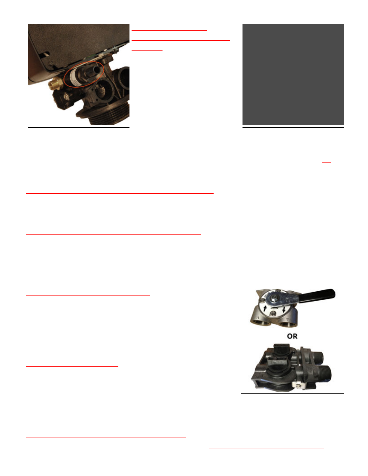
VV ee r r i i f f y y $$ oo ww dd i i r r ee c c t t i i oo nn . .
**!!**
Untreated water will enter the
system on the side marked with an arrow pointing toward the front
of the control head (on both the bypass valve and the control head
itself). Treated water will exit the system on the side marked with
an arrow pointing away from the front of the control head (on both
the bypass valve and the control head itself).
** ! ! **
CC oo r r r r ee c c t t i i nn l l ee t t / / oo uu t t l l ee t t c c oo nn nn ee c c t t i i oo nn s s aa r r ee vv i i t t aa l l . .
**!!**
Improper $ow direction will prevent proper
operation and can damage your system and your plumbing.
** ! ! **
TT hh ee dd i i r r ee cc t t i i oo nn oo f f $$ oo ww cc aa nn nn oo t t bb ee
15 of 19
IImmgg%%
11 55
%%--%%
BB y y pp a a s s s s PP oo s s i i t t i i oo nn
cc hh aa nn gg ee dd . .
**!!**
Turning the bypass upside down will not change the direction of the water $ow.
** **
II tt ii ss rr ee cc oo mm mm ee nn dd ee dd ttoo kk ee ee pp tt hh ee bbyy pp aa ss ss ii nn tt hh ee ss ee rr vv ii cc ee pp oo ss ii tt ii oo nn
ww h h e e n n mm a a k k i i n n g g p p l l u u mm b b i i n n g g c c o o n n n n e e c c t t i i o o n n s s a a n n d d t t u u r r n n i i t t t t o o b b y y p p a a s s s s ww h h e e n n
## r r s s t t t t uu r r nn i i nn gg t t hh ee ww a a t t ee r r bb a a c c k k oo nn . .
****
II mm gg %%
11 55
shows the bypass
position. In service position the handles will be turned 90-degrees
and be perpendicular to the inlet and outlet #ttings.
** ! ! **
WW h h e e n n s s o o l l d d e e r r i i n n g g d d o o n n o o t t s s o o l l d d e e r r d d i i r r e e c c t t l l y y t t o o t t h h e e i i n n c c l l u u d d e e d d
cc oo nn nn ee cc tt i i oo nn oo rr cc l l oo ss ee tt oo tt hh ee cc oo nn tt rr oo l l cc oo nn tt rr oo l l hh ee aa dd . .
**!!**
First solder a
short (min 3-inch [7.6-cm]) piece of copper pipe onto the adapters,
away from the valve, before connecting the adapter to the bypass or
yoke #tting.
** ! ! **
FF oo r r t t hh r r ee aa dd ee dd cc oo nn nn ee cc t t i i oo nn ss , , dd oo NN OO TT t t i i gg hh t t ee nn t t hh ee aa dd aa pp t t ee r r ss i i nn tt oo ## t t t t i i nn gg ss ww hh i i l l ee t t hh ee yy aa r r ee cc oo nn nn ee cc t t ee dd
tt oo tt hh ee cc oo nn tt rr oo l l hh ee aa dd . .
**!!**
Disconnect the bypass or yoke #tting, and connect the adapter using a high
quality thread sealant (pipe joint compound or Te$on/PTFE tape), and replace.
** ! ! **
WW h h e e n n i i n n s s t t a a l l l l e e d d t t h h e e b b y y p p a a s s s s v v a a l l v v e e c c a a n n mm o o v v e e u u p p a a n n d d d d o o w w n n , , t t h h i i s s i i s s n n o o r r mm a a l l . .
**!!**
77
——
PP LL AA CC EE SS YY SS TT EE MM II NN SS EE RR VV I I CC EE
Once all plumbing is done and plumbing connections have been checked for leaks you can place the
system in service.
77
..
11
——
OO p p e e n n b b y y p p a a s s s s v v a a l l v v e e
** ! ! **
ss l l oo ww l l yy
**!!**
If you have more than one system, enure the other systems are bypassed to prevent any possible
problems. Open a faucet that is near the system, a laundry sink or outside faucet (if it will be treated by
the system) is ideal, this will allow the air to bleed out of the system.
** ! ! **
SS l l oo ww l l yy
**!!**
open up the bypass
valve just to the point of allowing water to enter the system at a trickle, and leave it like that until the
tank is full of water. If you pre#lled the system it should only take a minute or two. Once the tank is full,
slowly open the bypass valve the rest of the way. Allow water to run out of the faucet for 15-20 minutes
to ensure all the air is worked out of the tank and o!of the , then close the faucet.
77
..
22
——
** ! ! **
CC hh ee c c kk f f oo r r l l ee aa kk s s
**!!**
Check the system for any leaks, paying attention to the seal between the tank and control head as well
as the connections between the bypass valve and control head. Open a nearby faucet and check to
ensure there is no leaks that show up when water is running.
77
..
33
——
FF l l uu ss hh t t hh ee ss yy ss t t ee mm
16 of 19
Open a nearby faucet. The water may be discolored at #rst, this is normal. Let water run out of the
faucet for at least 10 minutes, or until any discoloration clears up. Depending on the system this may be
almost immediate, or it may take a couple of hours. Once the water is cleared up a manual regeneration
should be run.
77
..
44
——
II nn ii tt ii aa tt ee mm aa nn uu aa ll rr ee gg ee nn ee rr aa tt ii oo nn
It is a good idea to allow the system to run through a manual cycle. On mechanical valves, turn the main
knob until it clicks into the #rst position. On digital systems, hold the extra cycle button for 5-10 second
until the backwash starts.
77
..
55
——
VV ee r r i i f f y y pp r r oo pp ee r r oo pp ee r r a a t t i i oo nn
Watch the system as it steps through each cycle, make sure it moves to each position, that water is not
leaking from any other #ttings, and that water is $owing down the drain line. The brine line will have
water $owing through it during the appropriate cycles as well.
** **
PP l l ee aa s s ee NN oo t t ee : :
****
With the brine tank
empty the system will not draw water out of the brine tank during the brine draw cycle. This cycle can
be skipped during the initial startup by pressing the extra cycle button after the
[[ BB DD ]]
cycle has started
counting down. The resin is precharged and the brine water is not needed for the #rst cycle, the initial
cycle is run to ensure the brine tank has the correct amount of water for the #rst automatic cycle.
** **
BB ee s s uu r r ee t t oo r r ee t t uu r r nn a a nn y y oo t t hh ee r r s s y y s s t t ee mm s s t t oo t t hh ee s s ee r r v v i i c c ee pp oo s s i i t t i i oo nn . .
****
FF r r ee qq uu ee nn t t l l yy AA ss kk ee dd QQ uu ee ss t t i i oo nn ss
II NN VV E E NN T T OO RR Y Y AA NN DD SS EE TT UU PP
WW h h a a t t i i s s t t h h e e p p r r o o p p e e r r o o r r d d e e r r t t o o a a r r r r a a n n g g e e mm u u l l t t i i p p l l e e s s y y s s t t e e mm s s ? ?
If you are installing more than one tank system the typical order for installation is:
** **
ss ee dd i i mm ee nn tt ## l l tt ee rr >> pp HH ## l l tt ee rr >> i i rr oo nn ## l l tt ee rr >> cc aa rr bb oo nn ## l l tt ee rr >> ww aa tt ee rr ss oo ff tt ee nn ee rr >> aa rr ss ee nn i i cc ## l l tt ee rr
****
Whole house cartridge systems are typically installed after any tank systems, the Scale Sentry system
after the cartridge system(s), and any UV systems will be last.
DD o o I I n n e e e e d d a a pp r r e e ## l l t t e e r r ? ?
In most cases a pre#lter is not necessary. Since the system cleans itself most particulate in the water will
be trapped and rinsed o!by the regeneration cycle, eliminating the need for a sediment pre#lter. If you
have a lot of sand in the water a spin down #lter (part #SDF-100) is recommended to protect the control
head
. For water supplies with high levels of chlorine a carbon pre#lter is recommended to extend resin
life.
MM y y p p o o l l y y g g l l a a s s s s t t a a n n k k a a r r r r i i v v e e d d a a n n d d s s i i t t s s c c r r o o o o k k e e d d , , ww h h a a t t d d o o I I d d o o ? ?
17 of 19
The black boot on the bottom of the tank may get knocked out of alignment during shipment. If your
tank is a bit tilted, simply pick the tank up 2–3 inches (5–8 cm) o!the $oor and drop it gently but #rmly
down, favoring the side that needs to be adjusted to make the tank stand straight.
II hh aa vv ee rr ee aa dd oo rr ss ee ee nn tt hh aa tt II ss hh oo uu ll dd nn '' tt ii nn ss tt aa ll ll tt hh ee tt oo pp dd ii ss tt rr ii bb uu tt oo rr bb aa ss kk ee tt ,, ii ss tt hh aa tt tt rr uu ee ??
The top distributor basket is used to help prevent resin from getting up into the control head and into
your pipes, it also keeps the resin from going down the drain during water or air surges. While systems
that are installed correctly and fuctioning properly will not have issues, the top basket is included as a
saftey measure to prevent problems and it is recommended to use it if present. Those who recommend
leaving it o!usually do so to prevent buildup on that basket that can lead to $ow restrictions (more
common in high iron waters), but it is usually easier to clean or replace a top basket periodically than
cleaning out clogged #xtures if something does go wrong.
AA f f t t ee r r i i nn s s t t a a l l l l i i nn gg t t hh ee bb y y pp a a s s s s i i t t s s t t i i l l l l mm oo v v ee s s uu pp a a nn dd dd oo ww nn , , i i s s t t hh a a t t nn oo r r mm a a l l ? ?
Yes. The bypass seals with O-ring and even when tightened down some movement will occur, without
leaking. The system requires this movement to allow for pressure changes in the system.
** ! ! **
DD o o n n o o t t
oo vv ee r r t t i i gg hh t t ee dd t t hh ee bb yy pp aa s s s s vv aa l l vv ee . .
**!!**
As long as the screws are snug enough to keep the bypass from
coming apart further tightening will just cause damage.
DD RR AA I I NN LL II NN EE
CC aa nn I I r r uu nn mm yy dd r r aa i i nn l l i i nn ee t t oo aa s s ee ww ee r r / / s s ee pp t t i i c c ? ?
Yes. These systems can be ran to your sewer or septic line and is typically the recommended place to run
the drain. Most concerns are related to the amount of water going down the drain, and a properly
designed septic/sewer system will not have a problem handling it. Studies have also shown that concerns
over salt in the wastewater a!ecting septic systems are unfounded and not a problem.
CC aa nn mm y y dd r r aa i i nn l l i i nn ee bb ee r r aa nn v v ee r r t t i i c c aa l l l l y y ? ?
Yes. Water from the drain comes out under pressure and can be ran vertically if needed.
BB RR I I NN EE TT AA NN KK
II ss tt hh ee rr ee ss uu pp pp oo ss ee dd tt oo bb ee ww aa tt ee rr ii nn tt hh ee bb rr ii nn ee tt aa nn kk ??
HH oo ww mm u u c c h h ww a a t t e e r r i i s s s s u u p p p p oo s s e e d d t t oo bb e e i i n n t t h h e e bb r r i i n n e e t t a a n n k k ? ?
During normal operation the system will have water in the brine tank so that it can dissolve the salt
needed for the next regeneration. The amount of water in the brine tank will vary depending on brine
tank size, system size, control head con#guration, system settins, and how much salt is in the brine tank.
Depending on those factors the water level in your brine tank may be only a few inches high or it may be
close to the over$ow.
HH oo ww mm u u c c h h s s a a l l t t s s h h o o u u l l dd I I p p u u t t i i n n t t h h e e b b r r i i n n e e t t a a n n k k ? ?
You can #ll the brine tank with as much salt as it will hold up to the top of the brine well. At a minimum
18 of 19
there should be enough salt for the next regeneration, the amount needed will vary depending on
system size and settings, but 1-2 bags of salt (40-80 pounds) will cover most systems.
HH oo ww o o f f t t e e n n dd o o I I n n e e e e d d t t oo a a dd d d s s a a l l t t t t oo t t h h e e bb r r i i n n e e t t a a n n k k ? ?
The rate at which you use salt will vary depending on system size, settings, water quality, and water use.
It is your choice to add salt freqently to keep the brine tank full or only add salt when it starts to get low.
Average homes will use 1-2 bags (40-80 pounds) of salt per month. Homes with high hardness or high
water usage can expect higher salt usage.
Version: 3C
Revised: 7/7/2017
© 2008-2017 Abundant Flow Water, Inc All Rights Reserved
19 of 19

Other manuals for 5600 Econominder

4

This manual suits for next models

1

Other Fleck Water Dispenser manuals

Fleck 5600 Econominder User manual

Fleck

Fleck 5600 Econominder User manual

Fleck 7000 User manual

Fleck

Fleck 7000 User manual

Fleck 6700 Downflow User manual

Fleck

Fleck 6700 Downflow User manual

Fleck 9100TS Upflow User manual

Fleck

Fleck 9100TS Upflow User manual

Fleck 5800 SXT User manual

Fleck

Fleck 5800 SXT User manual

Fleck 7000SXT User manual

Fleck

Fleck 7000SXT User manual

Fleck 5600SXT Owner's manual

Fleck

Fleck 5600SXT Owner's manual

Fleck 7000 Operating instructions

Fleck

Fleck 7000 Operating instructions

Fleck 9100SXT Meter Installation manual

Fleck

Fleck 9100SXT Meter Installation manual

Fleck 5600 Econominder User manual

Fleck

Fleck 5600 Econominder User manual

Fleck 5600SXT User manual

Fleck

Fleck 5600SXT User manual

Fleck 7000 User manual

Fleck

Fleck 7000 User manual

Fleck 5600 Econominder User manual

Fleck

Fleck 5600 Econominder User manual

Fleck 9000 User manual

Fleck

Fleck 9000 User manual

Fleck 7000SE User guide

Fleck

Fleck 7000SE User guide

Popular Water Dispenser manuals by other brands

Midea YL1335S-W Service manual

Midea

Midea YL1335S-W Service manual

Elkay EMABFDTL A Series Installation, care & use manual

Elkay

Elkay EMABFDTL A Series Installation, care & use manual

Culligan MEDALLIST SERIES owner's guide

Culligan

Culligan MEDALLIST SERIES owner's guide

Follett 25 Installation, operation and service manual

Follett

Follett 25 Installation, operation and service manual

Water Worker HT2B installation manual

Water Worker

Water Worker HT2B installation manual

Pure H2O QUATREAU SmartTap user guide

Pure H2O

Pure H2O QUATREAU SmartTap user guide

Elkay ezH2O Liv Pro installation manual

Elkay

Elkay ezH2O Liv Pro installation manual

ACORN AQUA A511103F Installation, operation and maintenance instructions

ACORN AQUA

ACORN AQUA A511103F Installation, operation and maintenance instructions

Water Control Dakotah series Installation & operation manual

Water Control

Water Control Dakotah series Installation & operation manual

BWT AQA Perla Instructions for assembly and use

BWT

BWT AQA Perla Instructions for assembly and use

Elba YL1632S instruction manual

Elba

Elba YL1632S instruction manual

Crystal Mountain Summit user manual

Crystal Mountain

Crystal Mountain Summit user manual

Coffee Queen HVA user manual

Coffee Queen

Coffee Queen HVA user manual

Everpure QC7I Series Installation and operation guide

Everpure

Everpure QC7I Series Installation and operation guide

Panasonic NC-ER22N operating instructions

Panasonic

Panasonic NC-ER22N operating instructions

Aquaport AQP-24CS user manual

Aquaport

Aquaport AQP-24CS user manual

Puretec SOL-E1 Series user guide

Puretec

Puretec SOL-E1 Series user guide

Water Boss 550 Installation and service manual

Water Boss

Water Boss 550 Installation and service manual

manuals.online logo
manuals.online logoBrands
  • About & Mission
  • Contact us
  • Privacy Policy
  • Terms and Conditions

Copyright 2025 Manuals.Online. All Rights Reserved.