SKF MonoFlex B Series User manual

CBDO3AEN.doc 18.03.2014 Rev. 3A
SKF MonoFlex B Doser
(Translation from the original operating and maintenance instructions according to EU Di-
rective 2006/42/EC)

CBDO3AEN.doc 18.03.2014 Rev. 3A
TABLE OF CONTENTS
1 General description .........................................................................................................................................1
2 Design .............................................................................................................................................................1
3 Operation ........................................................................................................................................................1
3.1 B doser..............................................................................................................................................................................................1
3.2 The unfastening and fastening of dosers ...................................................................................................................................1
4 Settings...........................................................................................................................................................2
4.1 Adjustments to the B6-doser .......................................................................................................................................................2
5 Technical specification.....................................................................................................................................3
5.1 Technical data..................................................................................................................................................................................3
5.2 Connections......................................................................................................................................................................................3
5.3 Symbols ............................................................................................................................................................................................3
6 Troubleshooting ..............................................................................................................................................5
7 Spare parts .....................................................................................................................................................6
8 Contact information ........................................................................................................................................8
2 APPENDICES

CBDO3AEN.doc 18.03.2014 Rev. 3A 1 (8)
Warning Read and follow the safety precautions and general instructions and also the SKF instruc-
tion "Safety and general instructions for lubrication systems."." Failure to follow these instructions could
result in serious injury or damage to the lubrication system or the equipment that is lubricated.
1 General description
Note! Numbers in brackets are part numbers of drawings 461780 and 461803.
A doser group consists of a mounting rail (pos.1) and one or several dosers (pos.2) fastened to it. The mounting rail
divides the lubricant to the dosers, which feed the adjusted amount of lubricant to the lubrication points.
Note! B doser is suitable for use with lubricants up to the class NLGI-1.
2 Design
The doser includes a charging valve (pos.3), a dosing chamber (pos. 4), a dosing piston (pos.5) and a spring (pos.6). B6
doser is equipped with a dosage adjustment screw (pos.7).
3 Operation
3.1 B doser
The pressure in the line increases during pressurisation and the doser charging valve moves to its upper position. At
the same time lubricant flows past the charging valve and moves the dosing piston to its upper position. When the
dosing piston moves to its upper position, it pushes the adjusted lubricant dosage from the dosing chamber to the lu-
brication point.
After pressurisation the line pressure decreases and the charging valve moves to its lower position and closes. The
spring returns the dosing piston to its lower position and at the same time lubricant flows above the dosing piston to
the dosing chamber.
The line can be pressurised again when the pressure in the line has decreased and the dosing pistons of the dosers
have returned to the lower position.
3.2 The unfastening and fastening of dosers
The dosers are unfastened and fastened with a socket wrench.

CBDO3AEN.doc 18.03.2014 Rev. 3A 2 (8)
NOTE! When changing the dosers, make sure that there is no pressure in the system.
4 Settings
4.1 Adjustments to the B6-doser
1. Turn open the pipe connector of the doser’s lubrication piping outlet.
2. Turn open the locking nut in the upper part of the doser.
3. Adjust the dosage by turning the adjustment screw located above the locking nut.
4. Tighten the locking nut in the upper part of the doser.
5. Tighten the pipe connector of doser’s lubrication piping outlet.
Table 1 Drawing numbers for adjustment values
Doser type Code Drawing number
B1-G1/8-ZN-4 11391000 461780
B2-G1/8-ZN-4 11391050 461780
B3-G1/8-ZN-4 11391100 461780
B4-G1/8-ZN-4 11391150 461780
B5-G1/8-ZN-4 11391200 461780
B6-G1/8-ZN-4 11391250 461780
B1-G1/8-ZN-6 11391300 461780
B2-G1/8-ZN-6 11391350 461780
B3-G1/8-ZN-6 11391400 461780
B4-G1/8-ZN-6 11391450 461780
B5-G1/8-ZN-6 11391500 461780
B6-G1/8-ZN-6 11391255 461780
B1-G1/8-ZN-6-U 12800250 461803
B2-G1/8-ZN-6-U 12800260 461803
B3-G1/8-ZN-6-U 12800270 461803
B4-G1/8-ZN-6-U 12800280 461803
B5-G1/8-ZN-6-U 12800290 461803
B6-G1/8-ZN-6-U 12800300 461803

CBDO3AEN.doc 18.03.2014 Rev. 3A 3 (8)
5 Technical specification
5.1 Technical data
Table 2 Technical specifications for dosers
Quantity Value Unit Description
t -25…+80 °C Operating temperature range
pmax 150 bar Max. operation pressure
w x h x d 15 x 90 x 15
17 x 110 x 17
mm B1-B5 doser dimensions
B6 doser dimensions
5.2 Connections
Inlet, mounting rail
lubricant (1 pc), header piping inlet, pipe connector Ø 8 mm or lubrication pipe Ø 1/2”
Outlet, doser
lubricant (1 pc), lubrication piping outlet, outlet connector Ø 4 mm or Ø 6 mm or female thread NPT Ø 1/8”
5.3 Symbols
Table 3 The symbols of dosers
BX-xxx-Y-Z-UAbbreviation Description
B: B Lubrication system type, B
X: 1 Doser size, size 1
2 Doser size, size 2
3 Doser size, size 3
4 Doser size, size 4
5 Doser size, size 5
6 Doser size, size 6
xxx: G1/8 Fastening the doser to the mounting rail G1/8”
Y: ZN Doser material,
Zinc-coated and yellow-passivated steel
Z: 4 Lubricant outlet, pipe connector Ø 4 mm
6 Lubricant outlet, pipe connector Ø 6 mm
U: no symbol Lubricant outlet, pipe connector mm
U Lubricant outlet, female thread NPT 1/8”

CBDO3AEN.doc 18.03.2014 Rev. 3A 4 (8)
Example:
B2-G1/8-ZN-6
Fastening of doser to mounting rail G1/8”
Doser material, Zinc-coated and yellow-passivated steel
Lubricant outlet, hose connector Ø 6 mm
Lubrication system type, B; Doser size, size 2
Lubricant outlet: pipe connector mm
Table 4 Symbols of mounting rails
BPLD-XX-YY-UAbbreviation Description
BP: BP Mounting rail, Base Plate
LD: LD Lubrication system type, LD
XX: 0202 4-place mounting rail,
2 places for dosers on opposite sides
0303 6-place mounting rail,
3 places for dosers on opposite sides
04 4-place mounting rail
06 6-place mounting rail
YY: ZN Mounting rail material,
Zinc-coated and yellow-passivated steel
U: no symbol Lubricant inlet, pipe connector Ø 8 mm
U Lubricant inlet, lubrication pipe Ø 1/2”
S Lubricant inlet, female thread G1/4”
Example:
BPLD-04-ZN
Mounting rail, Base Plate
Lubrication system type, LD
Mounting rail size, 4 doser blocks
Mounting rail material, zinc-coated and yellow-
passivated steel
Lubricant outlet, pipe connector Ø 8 mm

CBDO3AEN.doc 18.03.2014 Rev. 3A 5 (8)
Table 5 Mounting rail codes
Mounting rail type Code
BPLD-0202-ZN 11392310
BPLD-0303-ZN 11392320
BPLD-04-ZN 11392330
BPLD-06-ZN 11392340
BPLD-08-ZN 11392350
BPLD-0808-ZN 11392360
BPLD-02-S 11392400
BPLD-0303-S 11392750
BPLD-04-S 11392500
BPLD-06-S 11392600
BPLD-0202-ZN-U 12800420
BPLD-0303-ZN-U 12800430
BPLD-04-ZN-U 12800400
BPLD-06-ZN-U 12800410
6 Troubleshooting
Note! Check the lubricant requirements from the manufacturer of the vehicle and the properties of the lubricant
from the lubricant manufacturer. Note that in addition to the application, operating temperature, rotation
speed and operating environment are also relevant factors when choosing the lubricant. For more infor-
mation on grease pumpability, please contact Oy SKF Ab.
Note! The lubrication disturbances of the critical lubrication points must be repaired immediately, since inade-
quate lubrication rapidly damages the equipment or machinery that is lubricated.
Note! In the event that the operation disturbance can not be repaired with the help of these instructions, please
contact the supplier immediately.

CBDO3AEN.doc 18.03.2014 Rev. 3A 6 (8)
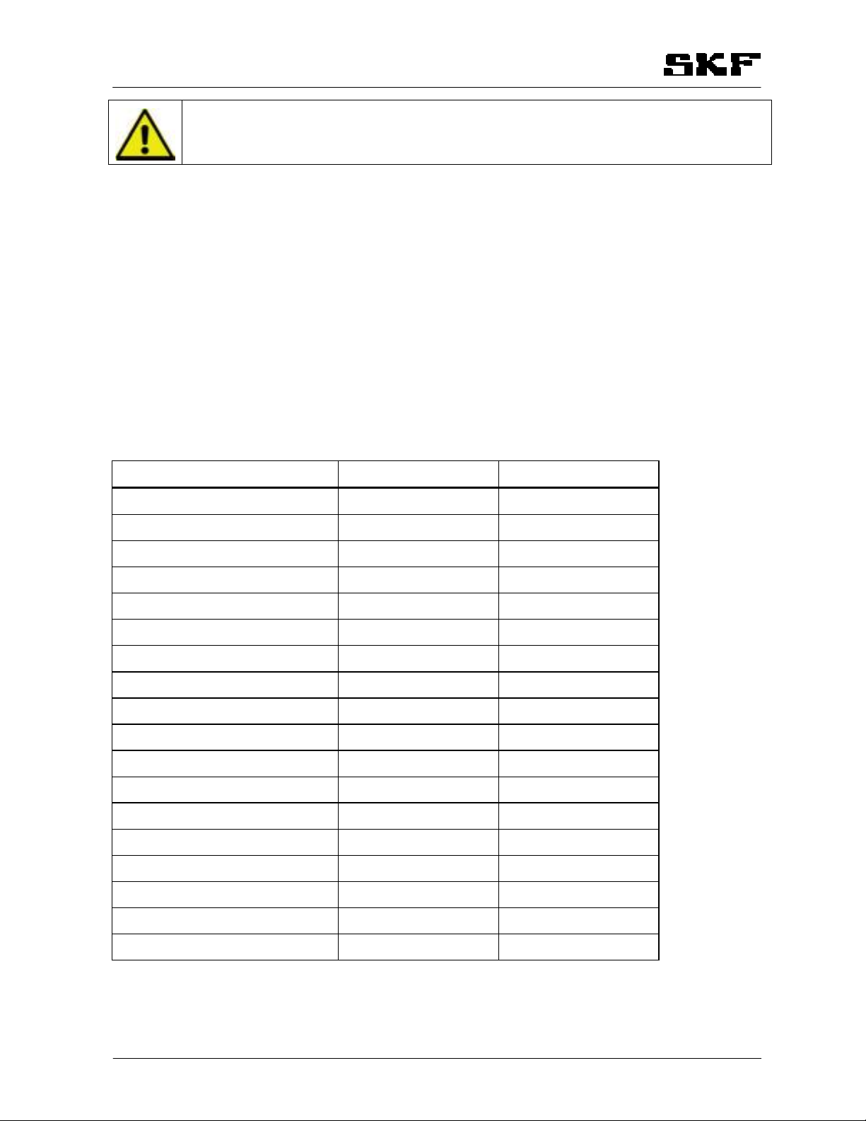
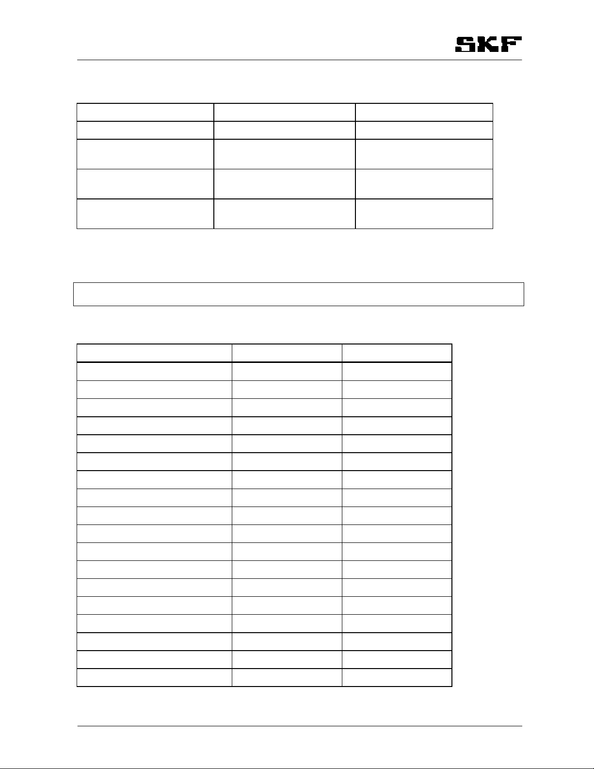
Table 6 Troubleshooting Table
Description of malfunction Cause of malfunction Solution
No lubrication spot receives lub-
ricant (line light A is flashing)
Dosers are leaking Replace the dosers
A lubrication point does not re-
ceive lubricant
Faulty doser Replace the doser
A lubrication point receives too
much lubricant
Leaking doser Replace the doser
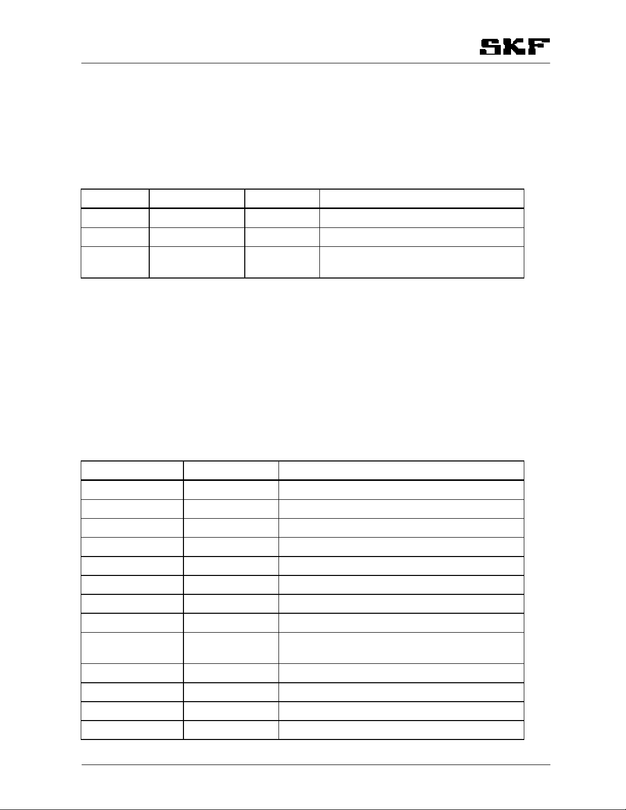
7 Spare parts
Note! The spare parts for dosers and mounting rails are complete replaceable products.
Numbers in brackets are part numbers of drawings 461780 and 461803.
Table 7 Doser codes
Doser type Code Drawing number
B1-G1/8-ZN-4 11391000 461780
B2-G1/8-ZN-4 11391050 461780
B3-G1/8-ZN-4 11391100 461780
B4-G1/8-ZN-4 11391150 461780
B5-G1/8-ZN-4 11391200 461780
B6-G1/8-ZN-4 11391250 461780
B1-G1/8-ZN-6 11391300 461780
B2-G1/8-ZN-6 11391350 461780
B3-G1/8-ZN-6 11391400 461780
B4-G1/8-ZN-6 11391450 461780
B5-G1/8-ZN-6 11391500 461780
B6-G1/8-ZN-6 11391255 461780
B1-G1/8-ZN-6-U 12800250 461803
B2-G1/8-ZN-6-U 12800260 461803
B3-G1/8-ZN-6-U 12800270 461803
B4-G1/8-ZN-6-U 12800280 461803
B5-G1/8-ZN-6-U 12800290 461803
B6-G1/8-ZN-6-U 12800300 461803
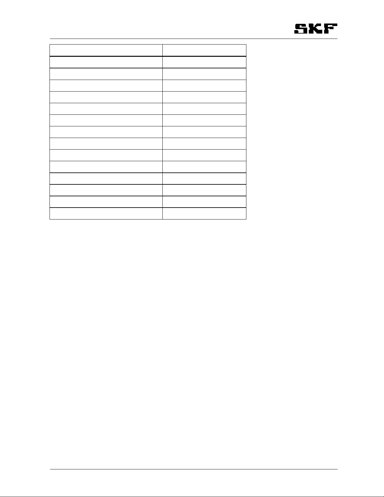
Table 8 Mounting rail codes

CBDO3AEN.doc 18.03.2014 Rev. 3A 7 (8)
Mounting rail type Code
BPLD-0202-ZN 11392310
BPLD-0303-ZN 11392320
BPLD-04-ZN 11392330
BPLD-06-ZN 11392340
BPLD-08-ZN 11392350
BPLD-0808-ZN 11392360
BPLD-02-S 11392400
BPLD-0303-S 11392750
BPLD-04-S 11392500
BPLD-06-S 11392600
BPLD-0202-ZN-U 12800420
BPLD-0303-ZN-U 12800430
BPLD-04-ZN-U 12800400
BPLD-06-ZN-U 12800410

CBDO3AEN.doc 18.03.2014 Rev. 3A 8 (8)
8 Contact information
Oy SKF Ab
P.O. Box 80 (Teollisuustie 6)
FI-40951 Muurame
FINLAND
Tel. +358 (0) 207 400 800
Fax. +358 (0) 207 400 899
www.skf.com

250
200
0
300
350
400
500
450
1
2
3
4
5
L
1
2
3
4
5
6
3
4
5
7
X
B1
B2
B3
B4
B5
20
LeL
10.9.2002
50
100
150
200
88 max
68
22
126
DOSAGE ADJUSTMENT B6
Turns
DOSERS B1 - B5
MODEL
B-DOSERS
DESIGN AND ADJUSTMENTS
DOSAGE/mm3
DOSAGE/mm3
L max. = 5 turns
DETAIL X
461780
DESIGNED
ITEM
DESCRIPTION
DETAIL DRAW
MATERIAL
DIM,PATT
QTY
MATERIAL DESCRIPTION
(WEIGHT KG)
SPECIFICATION OF PART
PREVIOUS DRG
FUTURE DRG
DATE
SCALE
DRAWING NUMBER
DRAWN
CODE / QTY / PART
Oy SKF Ab
MUURAME
FINLAND
SHEET/SHEETS

0
1
2
3
4
5
L
1
2
3
4
5
6
3
4
5
7
X
DETAIL X
B1
B2
B3
B4
B5
LeL
DOSAGE ADJUSTMENT B6
Dosage/oz
L max. = 5 turns
Turns
DOSERS B1 - B5
MODEL
DESIGN
B1-5-U, B6-U DOSERS
1/2"
0.0068
0.0084
0.0101
0.0118
0.0135
0.0152
0.0169
B1
B2
B3 B4 B5
0.0068
0.0051
0.0034
0.0017
0.0007
5.16" (130)
3.46" (88)
0.87" (22)
4.45" (113)
2.68" (68)
DOSAGE/oz
B6
461803 A
21.3.2005
1/8-27 NPT
DESIGNED
ITEM
DESCRIPTION
DETAIL DRAW
MATERIAL
DIM,PATT
QTY
MATERIAL DESCRIPTION
(WEIGHT KG)
SPECIFICATION OF PART
PREVIOUS DRG
FUTURE DRG
DATE
SCALE
DRAWING NUMBER
DRAWN
CODE / QTY / PART
Oy SKF Ab
MUURAME
FINLAND
SHEET/SHEETS
This manual suits for next models
36
Table of contents
Other SKF Industrial Equipment manuals
Popular Industrial Equipment manuals by other brands

Balluff
Balluff BNI IOL-104-011-K006 user guide

Proxxon
Proxxon MP 400 manual

4B
4B TouchSwitch TS1V4HT Installation and setup

Flowserve
Flowserve Limitorque HBC Series User instructions

Feltest
Feltest Capto user manual

Peter electronic
Peter electronic VersiComb II 230-3 Installation and commissioning instructions

Siemens
Siemens SIMATIC S7-1500R/H Equipment manual

RJS
RJS 448 quick start guide

HYDAC FILTER SYSTEMS
HYDAC FILTER SYSTEMS LVU-CD-10 Operating and maintenance instructions

JUKI
JUKI AF05 instruction manual

Archgard
Archgard I.H.E.A.T. Advantage 999-IHT-440 installation manual

ABB
ABB HT611945 Operation manual