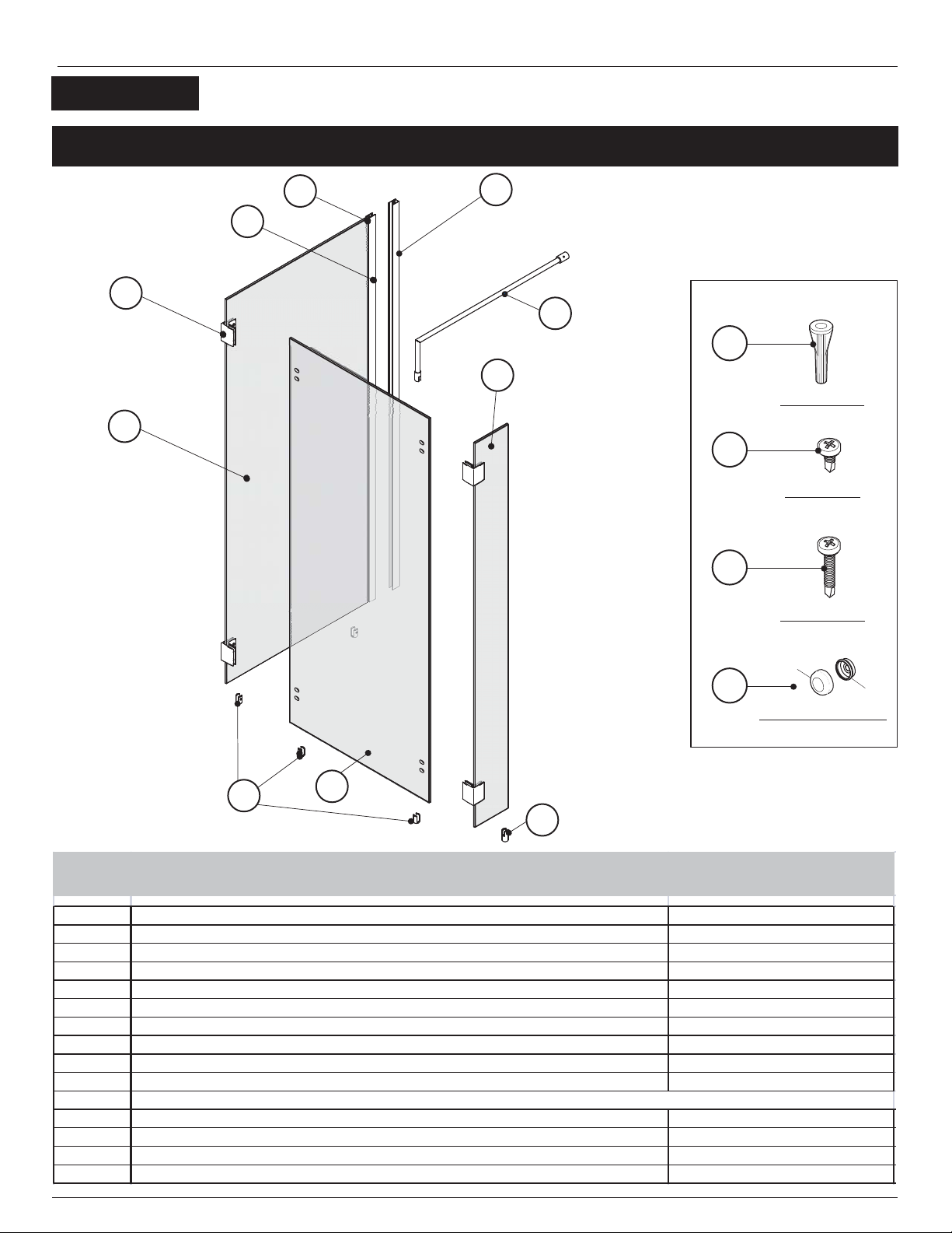
Fleurco Evolution 56307 User manual
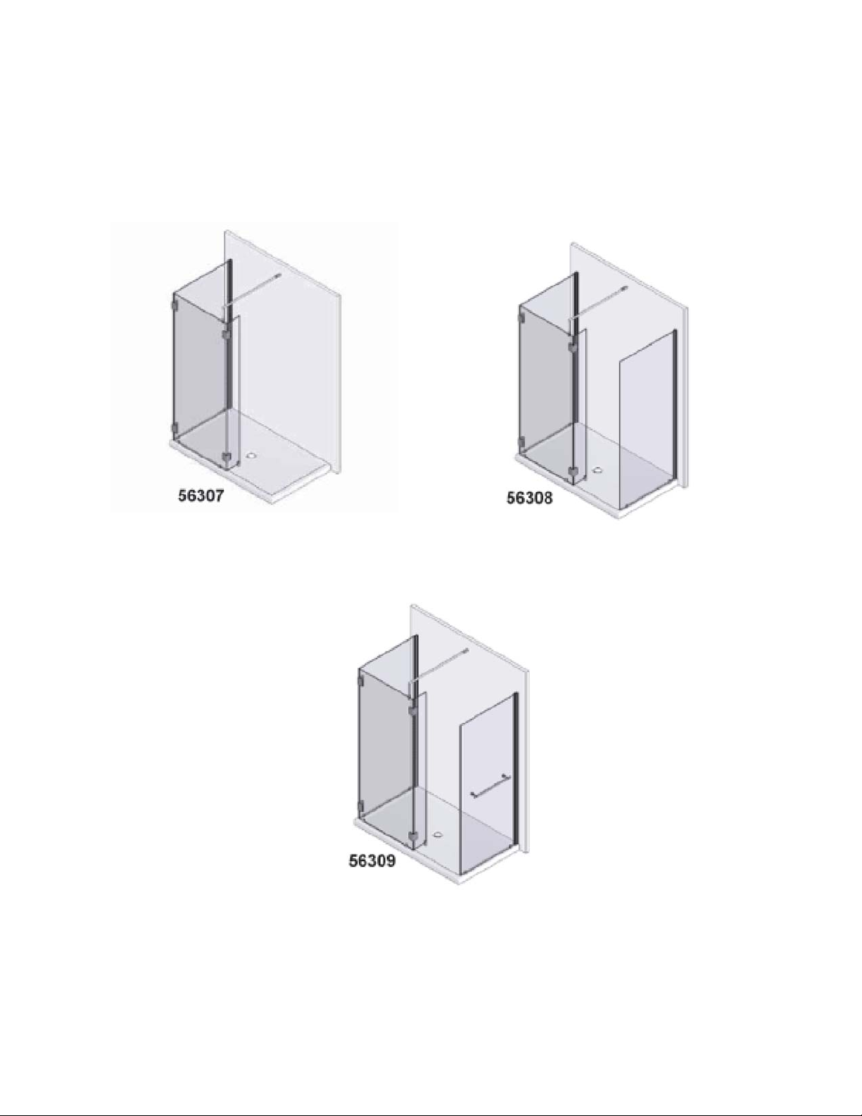


This manual suits for next models
5
Other Fleurco Bathroom Fixture manuals

Fleurco
Fleurco Gemini NPU5432-25-40 User manual

Fleurco
Fleurco Horizon NH148-40-75 User manual

Fleurco
Fleurco S014 User manual

Fleurco
Fleurco FW05 User manual

Fleurco
Fleurco STAK DUO LVSTB24-AP-RD Series User manual

Fleurco
Fleurco K202 User manual

Fleurco
Fleurco ABT4836-L2 User manual

Fleurco
Fleurco ABV3248 User manual

Fleurco
Fleurco N003 User manual

Fleurco
Fleurco T006 User manual

Fleurco
Fleurco EL02 User manual

Fleurco
Fleurco ABTL48 User manual

Fleurco
Fleurco ALN36 User manual

Fleurco
Fleurco Lexus PWJLR5836-11-40L-MC-65 User manual

Fleurco
Fleurco NM272-40-79 User manual

Fleurco
Fleurco ABN36 User manual

Fleurco
Fleurco ADT4836-3 User manual

Fleurco
Fleurco LA06 User manual

Fleurco
Fleurco Gemini G002 User manual

Fleurco
Fleurco Microtek PURA P227 User manual


Popular Bathroom Fixture manuals by other brands

Kohler
Kohler Mira Sport Max J03G Installation and user guide

Moen
Moen 186117 Series installation guide

Hans Grohe
Hans Grohe Raindance Showerpipe 27235000 Instructions for use/assembly instructions

Signature Hardware
Signature Hardware ROUND SWIVEL BODY SPRAY 948942 Install

fine fixtures
fine fixtures AC3TH installation manual

LIXIL
LIXIL HP50 Series quick start guide


