manuals.online logo
Brands
  1. Home
  2. •
  3. Brands
  4. •
  5. Flex-a-Lite
  6. •
  7. Fan
  8. •
  9. Flex-a-Lite Black Magic 150 User manual

Flex-a-Lite Black Magic 150 User manual

1 of 2
Black Magic
150
Mounting Instructions-150 may be installed either
horizontally or vertically to the radiator
Assemble the brackets and threaded rods to the
150 fan according to the specific application.
Mount the 150 with brackets using either the
bolt-on or clamp-on method.
Note:
• Be sure to use star nuts to stabilize the
threaded rods.
• Be sure the thermostatic sensing bulb
touches the radiator surface for accurate
temperature readings.
• Do not over tighten 150 to the radiator,
damage may occur.
Bolt-on Method Clamp-onMethod
StarNut
Radiator (Front)
Nut
Washer
×Threaded
Rod
×
×
×
Bracket
Radiator
Channel
×
Thermo.
SensingBulb
7/00 99981
MANDATORY CONNECTIONS
1. Disconnect the battery.
2. Connect the “+” terminal of the control box to a 12V positive (+) power source (i.e. fuse box), using the
wire provided in the kit.
Note: Attach this wire to an ignition controlled source to stop the fan when the vehicle is shut off.
Note: Attach this wire to a non-ignition source to keep the fan running after the vehicle is shut off.
3. Connect the “B” terminal to a high amp 12V positive power source (i.e. battery, alternator) using the
wire and in line circuit breaker provided in the kit.
Note: Circuit breaker is marked for proper installation.
4. Connect the “G” terminal to ground (i.e. chassis, negative side of battery) using the wire provided in
the kit.
5. If you have air conditioning: with 3-way connector provided, pass the A/C clutch positive(+)
wire (connected to the A/C pump) through the connector. Place the black wire provided into the
closed end of the connector. Crimp metal plate. Snap plastic cover into place. Attach black wire
to the "C" terminal of the
control box.
Air Conditioning Relay activates fan when A/C is turned on
ADJUSTING THE TEMPERATURE CONTROL
1. Attach the temperature control knob to the
control box.
2. Turn the knob clockwise completely.
3. Idle the vehicle, observe the temperature of
the vehicle. (Use the vehicles gauge)
4. When the temperature of the vehicle reaches
above normal, turn the control knob counter-
clockwise until the fan turns on. From here on
the fan should activate at this temperature
setting. Adjust as necessary according to your
vehicle needs.
OPTIONAL CONNECTIONS
Manual Switch (not included) - Allows
manual operation of the fan.
(This step is based on Flex-a-lite’s manual switch part
#31148, other switches may cause this unit to function
improperly.)
1. Connect the “M” terminal to terminal 1 on the
switch.
2. Attach terminal 2 of the switch to a 12V
positive (+) source.
3. Attach terminal 3 of the switch to ground, in
order to illuminate the switch.
Note (optional): To stop the fan from activating
thermostatically, omit the lead to the “+” termi-
nal of the control box. “B”, “G”, & “M” must
remain connected.
B
CMG+
Ground
12 Volt Positive Source
Control Box
Circuit
Breaker
Control Box Terminals & Connections
Mandatory Connections
+ 12 volt positive source
G Ground
B 12 volt positive source
C Air conditioning relay
Optional Connection
M Manual switch
12VoltSource
12 3
Ground
(Illuminate switch)
*WARNING: If not using Flex-a-lite's illumi-
nated switch (PN #31148) you must
disconnect the switch ground.
A/C positive (+)
wire from clutch
BAT
AUX
3-way
connector
2 of 2
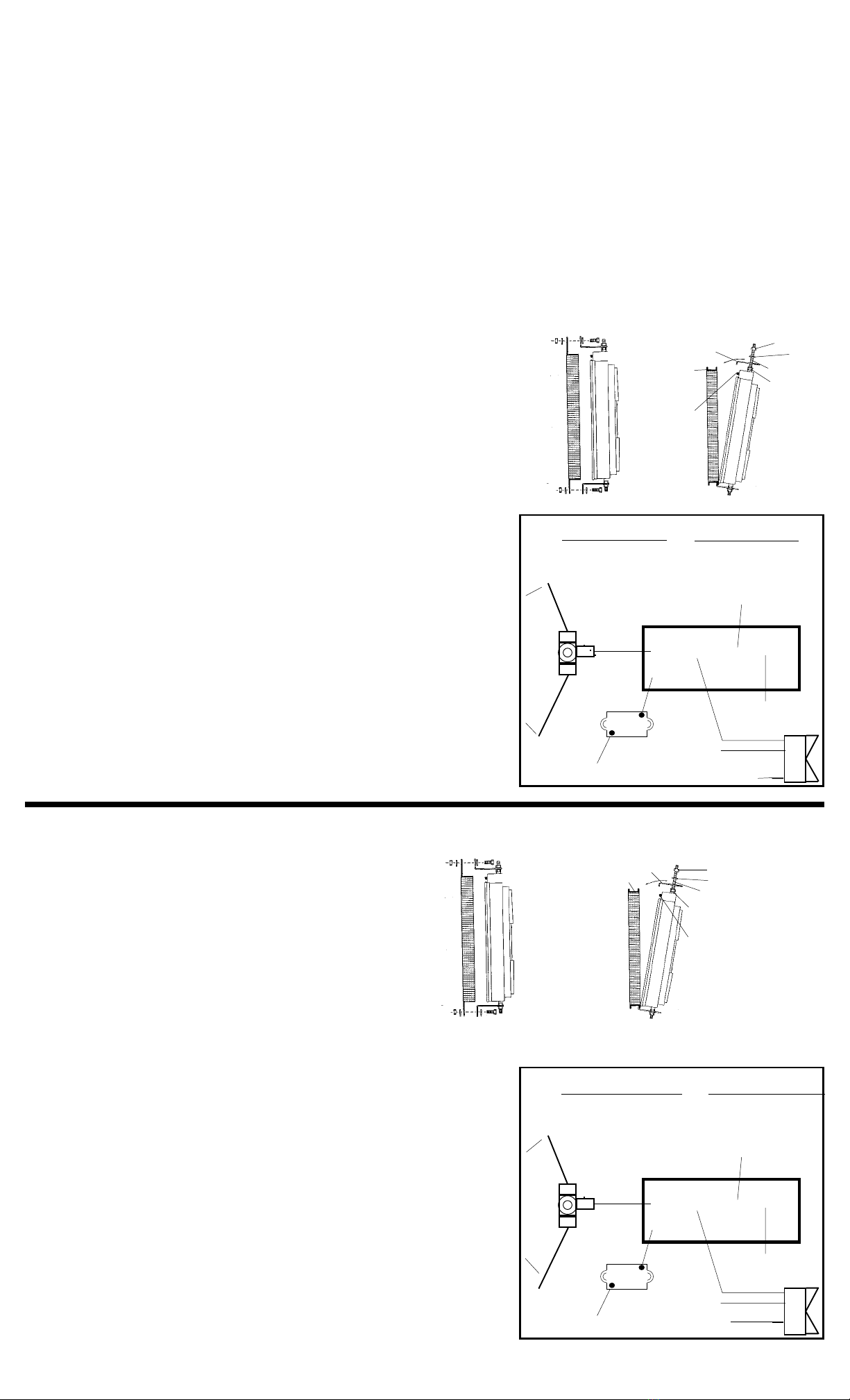
Instructions de montage - Le 150 peut être fixé au radiateur horizontalement ou verticalement
Fixez les pattes d’attache et le barres filetées au ventilateur 150 en fonction de votre application spécifique, en utilisant des boulons ou des
brides de fixation.
Note :
•Assurez-vous d’utiliser des écrous étoilés, afin de stabiliser les barres filetées.
•Assurez vous que la sonde de température touche la surface du radiateur, afin d’obtenir des
mesures précises.
•Ne serrez pas le 150 trop fort contre le radiateur, afin d’éviter de l’endommager.
Connexionsobligatoires
1. Déconnectez la batterie.
2. Connectez la borne positive “+” à une source de faible intensité de 12 volts positive (+)
au moyen du fil fourni avec le kit.
Note (facultatif) : Connectez la borne positive (+) à une source d’allumage, pour empêcher le ventilateur
de fonctionner quand le moteur est arrêté.
3. Connectez la borne “B” à une source de courant de haute intensité de 12 volts positive
(+), c’est-à-dire à la borne positive de la batterie ou de l’alternateur, au moyen du fil et
du disjoncteur en série inclus dans le kit.
Note : Le mode d’installation correct du disjoncteur figure sur ce dernier.
4. Connectez la borne “G” à la terre (c’est-à-dire au châssis ou à la borne négative (-) de la
batterie) au moyen du fil fourni avec le kit.
5. Connectez le fil positif (+) de l’embrayage de la climatisation au moyen du fil et du
connecteur à trois voies fournis. Lorsque la climatisation est enclenchée, le relais de la
climatisation actionne le ventilateur.
6. Réglez le thermostat à la température désirée entre 180 F (82 C) et 240 F (115 C).
Connexionfacultative
Le commutateur manuel (non inclus) permet de faire fonctionner le ventilateur manuellement.
(Note : en fonction du commutateur manuel Flex-a-Lite numéro 31148)
1. Connectez la borne “M” à la borne 1 du commutateur.
2. Connectez la borne 2 à une source de 12 volts positive (+).
3. Connectez la borne 3 à la terre, afin d’illuminer le commutateur.
Note (facultatif) : Pour éviter que le thermostat n’actionne le ventilateur, ne connectez pas la rne positive
(+) du coffret de commande. B, G et M doivent être connectés.
Instrucciones de montaje-El 150 se puede instalar sobre el radiador, ya sea horizontal o verticalmente
Ensamblelasménsulasylasvarillasroscadasalventilador150,segúnlaaplicaciónespecífica.Monteel150conménsulas,utilizandoyaseael
método de empernado o el de agarre.
Nota:
•Asegúrese de utilizar tuercas de estrella para estabilizar varillas roscadas.
•Asegúrese de que el bulbo sensor termostático toque la superficie del
radiador para tener lecturas precisas de temperatura.
•No apriete en exceso el 150 sobre el radiador porque podrían producirse daños.
Conexionesobligatorias
1. Desconecte la batería.
2. Conecte la terminal positiva “+” a una fuente de alimentación
positiva (+) de 12 volts y bajo amperaje, utilizando el cable que
se proporciona en el estuche.
Nota (opcional): Conecte la terminal positiva (+) a una fuente de encendido para que el ventilador deje de funcionar cuando se apague el motor.
3. Conecte la terminal “B” a una fuente de alimentación positiva (+) de 12 volts y alto amperaje, o sea, al borne positivo (+) de la batería o el
alternador, utilizando el cable y el disyuntor en línea que se incluyen en el estuche.
Nota: El disyuntor está marcado para que su instalación sea correcta.
4. Conecte la terminal “G” a tierra (o sea, al chasis o el borne negativo
(-) de la batería), utilizando el cable proporcionado con el estuche.
5. Con el cable y el conductor en tres sentidos que se proporcionan, haga un
empalme al cable positivo (+) del embrague del aire condicionado. Conecte
el otro extremo del conductor a la terminal “C” de la caja de control.
Elrelédelaireacondicionado-Activaelventiladorcuando se enciendeel aire acondicionado
6. Ajuste el termostato a la temperatura deseada,dentrode 180°F-240°F (82°C-115°C).
Conexiónopcional
Interruptor manual (no incluido) - Permite la activación manual del ventilador
(Nota: Basado en el interruptor manual, pieza número 31148 de Flex-a-lite.
1. Conecte la terminal “M” a la terminal 1 del interruptor.
2. Acople la terminal 2 a la fuente de alimentación positiva (+) de 12 volts.
3. Fije la terminal 3 a tierra para iluminar el interruptor.
Nota (opcional): Paraimpedirqueelventiladorseactive termostáticamente, omita elcable a
la terminal positiva (+) de la caja de control. B, G y M deberán permanecer conectadas.
1 2 3
B
CMG+
s
s
BAT
AUX
1 2 3
B
CMG+
s
BAT
AUX
Méthode par serrage de boulons
Méthode bride de fixation
Patte d’attache
Canal de
radiateur
Boulon
Rondelle
Tige filetée
Ecrou étoilé
Sonde de
température
Radiateur
(face avant)
Bornes et connexions du coffret de commande
Connexions obligatoires
+ Source de courant de faible
intensité de 12 volts
G Terre
B Source de courant de haute
intensité de 12 volts
C Relais de la climatisation
Connexions facultatives
M Commutateur manuel
s
Fil positif de la climatisation
Connecteur
à 3 voies Coffret de commande
Terre
Source de courant de
faible intensité
de 12 volts
Disjoncteur
Source de courant de haute
intensité de 12 volts
Source
de12 volts
Terre (illumination
du commutateur)
Método empernado Método de agarre
Canal del
radiador
Ménsula Tuerca
Roldana (arandela)
Varilla roscada
Tuerca de estrella
Bulbo termosensor
Radiador
(frente)
Terminales y conexiones de la caja de control
Conexiones obligatorias
+ Fuente de bajo amperaje
de 12 volts
G Tierra
B Fuente de alto amperaje
de 12 volts
C Relé de aire acondicionado
Conexiones opcionales
M Interruptor manual
Cable positivo del aire
acondicionado
Conector en
tres sentidos Caja de control
Tierra
Fuente de 12
volts de bajo
amperaje
Disyuntor
Positivo de 12
volts de alto
amperaje
Fuente de
alimentación de 12
voltsTierra
(se ilumina el interruptor)
THE FLEX-A-LITE LIMITED WARRANTY
Flex-a-lite Corporation, P.O. Box 580, Milton, Washington 98354, Telephone No.. 253/922-2700, warrants to the original purchaser User, all
Flex-a-lite products to be free of defects in material and workmanship for a period of 365 days (1 year) from date of purchase. Flex-a-lite
products failing within 365 days (1 year) from date of purchase, may be returned to the factory through the point of purchase, transportation
charges prepaid. If, on inspection, cause of failure is determined to be defective material or workmanship and Not be misuse, accident, or
improper installation, Flex-a-lite will replace the fan free of charge, transportation prepaid. Flex -a-lite will Not be liable for incidental,
progressive, or consequential damages. Some states do Not allow the ex clusion or limitation of incidental or consequential damages, so
the above limitation or ex clusion may Not apply to you. This warranty gives you specific legal rights and you may also have other rights, which vary
from state to state.
NOTE: The Flex-a-lite warranty is in compliance with the Magnuson-Moss Warranty Act of 1975.

Other Flex-a-Lite Fan manuals

Flex-a-Lite 314 User manual

Flex-a-Lite

Flex-a-Lite 314 User manual

Flex-a-Lite Trimline Electric Fans User manual

Flex-a-Lite

Flex-a-Lite Trimline Electric Fans User manual

Flex-a-Lite Black Magic 155 User manual

Flex-a-Lite

Flex-a-Lite Black Magic 155 User manual

Flex-a-Lite Black Magic 150 User manual

Flex-a-Lite

Flex-a-Lite Black Magic 150 User manual

Flex-a-Lite Black Magic Extreme 185 User manual

Flex-a-Lite

Flex-a-Lite Black Magic Extreme 185 User manual

Flex-a-Lite 290 User manual

Flex-a-Lite

Flex-a-Lite 290 User manual

Flex-a-Lite 110 User manual

Flex-a-Lite

Flex-a-Lite 110 User manual

Flex-a-Lite LoBoy 118 Puller User manual

Flex-a-Lite

Flex-a-Lite LoBoy 118 Puller User manual

Flex-a-Lite 130 User manual

Flex-a-Lite

Flex-a-Lite 130 User manual

Flex-a-Lite 678 User manual

Flex-a-Lite

Flex-a-Lite 678 User manual

Flex-a-Lite 285 User manual

Flex-a-Lite

Flex-a-Lite 285 User manual

Flex-a-Lite 330 User manual

Flex-a-Lite

Flex-a-Lite 330 User manual

Flex-a-Lite 410 User manual

Flex-a-Lite

Flex-a-Lite 410 User manual

Flex-a-Lite 280 User manual

Flex-a-Lite

Flex-a-Lite 280 User manual

Flex-a-Lite 575 User manual

Flex-a-Lite

Flex-a-Lite 575 User manual

Flex-a-Lite Black Magic 175 User manual

Flex-a-Lite

Flex-a-Lite Black Magic 175 User manual

Flex-a-Lite 340 User manual

Flex-a-Lite

Flex-a-Lite 340 User manual

Flex-a-Lite 40 User manual

Flex-a-Lite

Flex-a-Lite 40 User manual

Flex-a-Lite 295 User manual

Flex-a-Lite

Flex-a-Lite 295 User manual

Flex-a-Lite 675 User manual

Flex-a-Lite

Flex-a-Lite 675 User manual

Flex-a-Lite 10 User manual

Flex-a-Lite

Flex-a-Lite 10 User manual

Flex-a-Lite 130 User manual

Flex-a-Lite

Flex-a-Lite 130 User manual

Flex-a-Lite 278 User manual

Flex-a-Lite

Flex-a-Lite 278 User manual

Flex-a-Lite 294 User manual

Flex-a-Lite

Flex-a-Lite 294 User manual

Popular Fan manuals by other brands

Cosmo RRV 100.1 manual

Cosmo

Cosmo RRV 100.1 manual

Orbegozo PWS 0165 instruction manual

Orbegozo

Orbegozo PWS 0165 instruction manual

Hunter 22390 owner's guide

Hunter

Hunter 22390 owner's guide

Lava Aire Fantom user guide

Lava Aire

Lava Aire Fantom user guide

Beper P206VEN151 Use instruction

Beper

Beper P206VEN151 Use instruction

impress IM-712W Use and care book

impress

impress IM-712W Use and care book

Makita CF100D owner's manual

Makita

Makita CF100D owner's manual

Holmes HTF3110A owner's guide

Holmes

Holmes HTF3110A owner's guide

Zoo Fans IC15-MF installation guide

Zoo Fans

Zoo Fans IC15-MF installation guide

Nuaire Group LPXBOXDC-2 Installation and Maintenance

Nuaire Group

Nuaire Group LPXBOXDC-2 Installation and Maintenance

Hunter 90434 owner's manual

Hunter

Hunter 90434 owner's manual

Casablanca WHITMAN owner's manual

Casablanca

Casablanca WHITMAN owner's manual

Hinkley TEMPEST 70" owner's manual

Hinkley

Hinkley TEMPEST 70" owner's manual

Honeywell ER90 owner's guide

Honeywell

Honeywell ER90 owner's guide

World Power Technologies WHISPER H20 datasheet

World Power Technologies

World Power Technologies WHISPER H20 datasheet

ARRANMORE AR-2339 Use and care guide

ARRANMORE

ARRANMORE AR-2339 Use and care guide

Westinghouse Capitol owner's manual

Westinghouse

Westinghouse Capitol owner's manual

Steba VT 4 Instructions for use

Steba

Steba VT 4 Instructions for use

manuals.online logo
manuals.online logoBrands
  • About & Mission
  • Contact us
  • Privacy Policy
  • Terms and Conditions

Copyright 2025 Manuals.Online. All Rights Reserved.