FlexiForce ISC-NL Maintenance and service guide
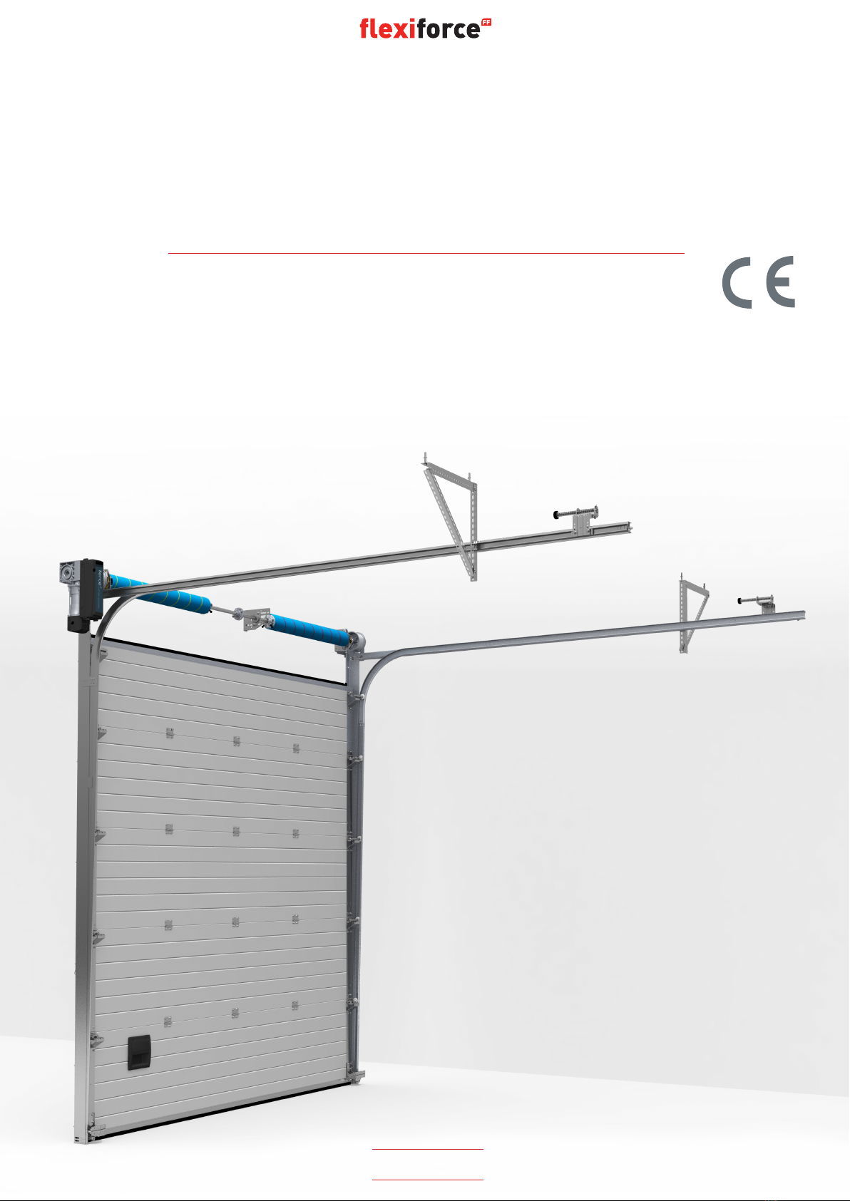
ISC-NL
INSTALLATION / MAINTENANCE
INSTRUKCJA MONTAŻU/KONSERWACJI
MANUAL
WWW.FLEXIFORCE.COM
INDUSTRIAL HARDWARE SET FOR OVERHEAD DOORS PRZEMYSŁOWY ZESTAW
MONTAŻOWY DO BRAM SEKCYJNYCH
SYSTÈME QUINCAILLERIE INDUSTRIEL
manual
ATTENTION! GENERAL WARNINGS!
To install, use and maintain this door safely, a number of precautions must
betaken. For the safety of all concerned pay heed to the warnings and
instructions given be low! If in doubt, contact your supplier.
SPECIAL SAFETY WARNINGS OR REMARKS IN THIS MANUAL ARE
INDICATED WITH THIS SYMBOL:READ THESE WARNINGS CAREFULLY.
9This manual has been written for use by experienced fitters and as such is not suitable for d.i.y. purposes or for
use by trainee fitters.
9This manual describes the installation of the hardware set components, door sections (panels) and refers to
installation manuals of the electrical operators. Be sure to supplement this manual if needed with instructions
for any additional components not described in this manual.
9Before starting, read this manual carefully!
9Certain components may be sharp or have jagged edges. As such you are advised to wear safety gloves.
9All the components which have been supplied are designed for use with this specific overhead door.
Replacement or adding additional components may have an adverse effect on the safety of, and the guarantee
on, the door. Also the CE-approval which has been granted to this door combination will be cancelled when
components are changed or installation is not done according to this manual! Installer is responsible for this.
9During tensioning, springs can exert large forces. Work carefully. Use the proper equipment. Ensure that you
are standing in a steady position.
9Ensure that there is sufficient light during installation. Remove obstacles and dirt. Make sure that there is no
one else present other than the fitters. Other people (children!) may get in the way or endanger themselves
during the installation.
9Ensure that the building is constructed strong enough to carry the overhead door construction. It is the
responsibility of the installing company to use fixing materials which are strong enough and equipped to fix the
overhead door to the building.
9A power operated overhead door may not be equipped with a pull cord (rope). Be sure that this has been
removed when a manual operated door is being equipped with an E-operator.
9Environments closed by an electrical operated overhead door with operators which are not disconnectable and
where the door cannot be manual operated must be equipped with a pass door.
9Cutting of the bottom section is not allowed. The forces on cable break devices and bottom brackets are too
high. Cutting is weakening the construction of the door on this critical point.
This door can only be taken into use, when all instructions are followed and:
9The installer has checked the combination of hardware, panel and e-operator as being approved and safe. Make
sure to check the max. peak force and the proper functioning of the safety edge system in combination with the
operator.
9All documentation has been handed over to the end-user: IIa Declaration of conformity, User Guide,
Maintenance Instructions, Dismantling instructions, Service Log Book and this manual.
9A CE-identification plate has been placed on the door.
9User has been given instructions and demonstration of the proper use and functioning of the door.
Manual ISC-NL www.flexiforce.com

manual
UWAGA! OSTRZEŻENIA!
Montaż , użycie i obsługa elementów zestawu montażowego wymagają
przestrzegania szeregu zasad . Poniżej przedstawione są warunki
bezpieczeństwa których przestrzeganie jest niezbędne ! W przypadku
wątpliwości należy skontaktować się z dostawcą.
OSTRZEŻENIA DOTYCZĄCE BEZPIECZEŃSTWA I INNE ISTOTNE UWAGI
OZNACZANE SĄ SPECJALNYM SYMBOLEM : NALEŻY JE BARDZO UWAŻNIE
PRZECZYTAĆ .
9Instrukcja przeznaczona jest wyłącznie dla przeszkolonych instalatorów i nie może być wykorzystywana w
celach treningowych lub innych , niezgodnych z przeznaczeniem .
9Instrukcja opisuje wyłącznie montaż elementów zestawu, sekcji oraz może stanowić uzupełnienie instrukcji
montażu napędów elektrycznych. W przypadku użycia elementów dodatkowych , nie prezentowanych w tej
instrukcji, wymagane jest przeczytanie opisów uzupełniających wyjaśniających sposób ich montażu.
9Przed przystąpieniem do montażu , należy uważnie przeczytać całą instrukcję !
9Pewne elementy zestawu montażowego mogą posiadać ostre krawędzie , i dlatego koniecznym jest używanie
rękawic ochronnych .
9Wszystkie dostarczone części zaprojektowane są tak , aby stworzyć zestaw dla ściśle określonego rodzaju
bramy . Zamiana lub zastosowanie dodatkowych elementów może wpłynąć na pogorszenie efektów pracy
bramy, stworzyć zagrożenie oraz zmienić warunki gwarancji udzielanej przez producenta . Ponadto zamiana
części konstrukcyjnych lub wykonanie montażu w sposób niezgodny z instrukcją skutkuje pozbawieniem
wszelkich aprobat CE dla wykonanej w ten sposób bramy! Odpowiedzialność za to leży po stronie instalatora.
9Podczas napinania sprężyn , gromadzona jest w nich bardzo duża energia . Należy pracować uważnie , stać
wygodnie na stabilnym podłożu oraz używać właściwych narzędzi .
9Miejsce montażu powinno być dobrze oświetlone , bez przeszkód i brudu . Inne osoby , a szczególnie dzieci ,
mogą być narażone na niebezpieczeństwo i dlatego nie mogą przebywać w pobliżu miejsca pracy instalatorów .
9Należy upewnić się czy konstrukcja budynku jest odpowiednio mocna i stabilna do mocowania na niej bramy
sekcyjnej. Firmy instalacyjne odpowiadają za jakość użytych materiałów do mocowania, muszą one pewnie
połączyć elementy bramy ze ścianami budynku.
9Bramy przeznaczone do obsługi napędem elektrycznym nie muszą posiadać linki do zamykania ręcznego. Jeśli
jest, to należy ją zdemontować po założeniu automatu.
9Jeśli brama posiada napęd elektryczny którego nie można wysprzęglić lub nie można jej obsługiwać ręcznie to,
ze względów środowiskowych, musi być ona wyposażona w furtkę dla ruchu pieszego.
9Docinanie dolnych paneli jest niedozwolone. Siły przenoszone na sekcje przez uchwyty dolne zabezpieczające
liny nośne są zbyt duże. Wzdłużne cięcie panelu osłabia konstrukcje bramy w miejscach najbardziej
przeciążanych.
Brama ta może zostać dopuszczona do użytkowania tylko wówczas, gdy została wykonana zgodnie ze
wszystkimi instrukcjami oraz:
9Montażysta skontrolował czy elementy konstrukcyjne są kompletne oraz czy spełniają one, wraz panelem i
napędem elektrycznym, wszystkie aprobaty oraz standardy bezpieczeństwa. Sprawdzeniu podlegać musi także
wartość sił szczytowych osiąganych w pracy z napędem oraz prawidłowość funkcjonowania krawędziowych
urządzeń zabezpieczających podłączonych do jego sterowania.
9Komplet dokumentów zastał przekazany użytkownikowi: Deklaracja Zgodności IIa, Instrukcja użytkowania,
Instrukcja konserwacji, Instrukcja demontażu, Książka serwisowa i poniższa Instrukcja montażu.
9Na bramie umieszczono naklejkę identyfikacyjną CE.
9Użytkownik został poinstruowany i zademonstrowano mu jak należy prawidłowo obsługiwać bramę.
www.flexiforce.com

manual
GWARANCJA, WARUNKI DOSTAW
Ogólne warunki dostawy i płatności ustalone przez Metaalunie i opisane jako METAALUNIE CONDITIONS w pełni
dotyczą wszystkich naszych kontraktów i zobowiązań . Inne formy warunków nie są zobowiązujące . Kopia warunków
dostawy i płatności może być dostarczona na żądanie bez dodatkowych opłat . Jest ona także dostępna na stronie
internetowej www.flexiforce.nl. Flexi-Force dokłada wszelkich starań aby dostawy były zgodne z zamówieniem w
100 % . W praktyce , pomimo starań , nie zawsze jest to możliwe . Powstałe błedy będą naprawiane najszybciej jak
to jest możliwe , tak aby zminimalizować odbiorcy wszelkie niedogodności z tego tytułu . W takim przypadku należy
bezzwłocznie poinformować o problemach dotyczących dostawy ( dokument musi zawierać numer zamówienia oraz
numer tygodnia produkcji ) i oczekiwać propozycji ich rozwiązania .
FlexiForcepokryjekosztybłędowponiesionychprzezosoby trzecie,tylkopowyjaśnieniuokolicznościiprzedstawieniu
stosownej zgody . Rekompensata finansowa oraz zwrot kosztów podróży dłuższej niż 1 godzina są obiczane na
podstawie zwykłych taryf.
Przy realizacji dużych projektów zalecamy rozpoczęcie prac od montażu jednej kompletnej bramy a dopiero potem
kontynuowanie instalacji następnych konstrukcji. Dzięki temu , ewentualne błedy lub niedopatrzenia mogą zostać
wykryte na wczesnym etapie zaawansowania robót i szybko usunięte przy minimalnych kosztach.
Instrukcja montażu nie narusza żadnych praw autorskich . Zmiany techniczne mogą być dokonywane bez uprzedniej
pisemnej informacji.
Flexi-Force zaprojektował konstrukcję i działanie elementów zestawu montażowego w zgodzie z normami Unii
Europejskiej . Jednakże należy sprawdzić czy rozumienie wszystkich norm jest zgodne z tym , jakie obowiązuje w
danym kraju .
Flexi-Force B.V., P.O. Box 37, 3770 AA Barneveld, The Netherlands
Tel. +31-(0)342-427777, info.nl@flexiforce.com
OBOWIĄZUJĄCE DYREKTYWY CE I OGRANICZENIA:
Przemysłowe bramy sekcyjne wprowadzane na rynek europejski muszą podlegać standardom określonym przez
Dyrektywę EMC ( EMC-Directive*), Dyrektywę Niskonapięciową (Low Voltage Directive*), Dyrektywę Maszynową
(Machine Directive*) i Dyrektywę Budowlaną (Construction Products Directive), wydaną przez CEN.
(* = dotyczy tylko bram obsługiwanych elektrycznie)
Flexi-Force zaprojektowała i produkuje zestawy montażowe zgodnie z przedstawionymi wyżej Dyrektywami.
Określają one maksymalne wymiary bram przemysłowych i sił szczytowych wystepujących podczas ich obsługi:
•Maksymalna szerokość : 8 metrów
•Maksymalna wysokość : 6 metrów
•Maksymalna waga bramy : 700 kg
•Bramy muszą być standardowo wyposażone w urządzenia zabepieczające przed upadkiem: zabezpieczenia
sprężyn , zabezpieczenia lin nośnych.
•Inne akcesoria zapewniające bezpieczeństwo: osłony rolek, czujniki zabezpieczające dolną krawędź bramy ( w
przypadku obsługi napędem elektrycznym), czujniki luźnej liny, prowadzenia lin nośnych wewnątrz prowadnic.
•Odpowiednio skonfigurowane komponenty podlegają testom CE w kombinacji z testowanymi panelami oraz
napędami /układami sterowniczymi.
•W bramach niższych niż 2,75m stosowane są sekcje zabezpieczone przed ściśnięcim palców.
•Nie dozwolone jest prowadzenie lin nośnych na zewnątrz prowadnic o ile nie są one osłonięte.
Dla bram opisanych w tej instrukcji FlexiForce przeprowadziła obligatoryjne TESTY WSTĘPNEGO RODZAJU (ITTR)
w Instytucie SP w Szwecji ( organ uprawniony o nr.0402). Uzyskany RAPORT Z TESTÓW WSTĘPNEGO RODZAJU
może być przekazany do firmy produkującej bramy o ile zadeklaruje ona zgodność ich wykonywania pod opisanymi
warunkami. Według normy EN13241-1 jest to element niezbędny, uzupełniający dokumentację techniczną. Nadany
numer ITTR powinien zostać umieszczony na bramie, na naklejce informacyjnej CE.
Kody towarowe użytych elementów zostały podane w instrukcji . Brama może zostać zainstalowana i certyfikowana
CE jedynie wówczas gdy użyte zostaną wszystkie części wyszczególnione w certyfikacie SP. Więcej szczegółów
można znaleźć na www.flexiforce.com.
www.flexiforce.com
ATTENTION ! AVERTISSEMENTS GENERAUX !
Certaines précautions doivent être prises pour pouvoir installer, utiliser
et entretenir cette porte en tout sécurité. Pour la sécurité de tous, tenez
compte des avertissements et des instructions ci-dessous ! En cas de doute,
contactez votre fournisseur.
LES AVERTISSEMENTS OU REMARQUES SPÉCIALES DE SÉCURITÉ DE CE
MANUEL SONT INDIQUÉS PAR CE SYMBOLE : LIRE ATTENTIVEMENT CES
AVERTISSEMENTS.
9Ce manuel a été écrit pour utilisation par des installateurs expérimentés et, en tant que tel, n’est pas destiné à
des fins de bricolage ou à des assistants installateurs.
9Ce manuel décrit l’installation des composants du kit de quincaillerie, des sections de porte (panneaux) et fait
référence aux manuels d’installation des opérateurs électriques. Veillez à fournir ce manuel si nécessaire avec
les instructions pour tout composant supplémentaire non décrit dans ce manuel.
9Avant de commencer, lisez attentivement ce manuel !
9Certains composants peuvent comporter des bords pointus ou dentelés. Il est donc conseillé de porter des
gants de sécurité.
9Tous les composants qui ont été fournis sont conçus pour utilisation avec cette porte résidentielle spécifique.
Tout remplacement ou ajout de matériel peut avoir des conséquences fâcheuses pour la sécurité et la garantie
de la porte. De plus, l’approbation CE qui a été accordée à cette combinaison de porte sera annulée si les
composants sont modifiés ou si l’installation n’est pas réalisée conformément à ce manuel ! L’installateur est
responsable de cela.
9Pendant la mise sous tension, des ressorts peuvent exercer des forces importantes. Soyez prudent. Utilisez
l’équipement adéquat. Veillez à vous trouver en position stable.
9Veillez à un éclairage suffisant pendant l’installation. Éliminez tous les obstacles et la saleté. Assurez-vous que
seuls les installateurs sont présents. Toute autre personnes (et en particulier les enfants !) peuvent être dans
le chemin et se mettre en danger lors de l’installation.
9Veillez à ce que le bâtiment soit suffisamment solide pour supporter la porte résidentielle. La société chargée
de l’installation est responsable de l’utilisation de matériaux de fixation suffisamment solides pour fixer la
porte résidentielle sur le bâtiment.
9Une porte sectionnelle électrique ne peut pas être équipée d’un câble de traction (corde). Veillez à ce que ce
câble de traction soit enlevé lorsqu’une porte manuelle est équipée d’un opérateur électrique.
9Les environnements fermés par une porte sectionnelle à commande électrique avec des opérateurs qui ne sont
pas déconnectables et où la porte ne peut pas être actionnée manuellement doivent être équipés d’un portillon.
9Il est interdit de découper la section inférieure. Les forces exercées sur les parachutes de câble et les plaques
de base sont trop élevées. Toute découpe affaiblirait l’ensemble de la porte à ce point critique.
Cette porte ne peut être utilisée que lorsque toutes les instructions ont été suivies et :
9que si l’installateur a vérifié et approuvé la combinaison de matériel, de panneau et d’opérateur électrique.
Veillez à contrôler la force maximale et le bon fonctionnement du système de sécurité en combinaison avec
l’opérateur.
9Toute la documentation a été remise à l’utilisateur final : IIa Déclaration de conformité, Guide de l’utilisateur,
Instructions de maintenance, Instructions de démontage, Carnet d’entretien et le présent manuel.
9Une plaque d’identification CE a été placée sur la porte.
9L’utilisateur a reçu des instructions et une démonstration lui a été faite de l’utilisation correcte et du
fonctionnement de la porte.
manualmanual
Manual ISC-NL www.flexiforce.com

GARANTIE, CONDITIONS
Les conditions générales de livraison et de paiement émises par Metaalunie et désignées comme les CONDITIONS
METAALUNIE sont pleinement applicables à tous nos devis et contrats et à leur mise en œuvre. Nous rejetons
explicitement toutes autres conditions. Sur demande, nous pouvons vous envoyer gratuitement une copie de ces
conditions. Une copie peut également être téléchargée depuis notre site Internet www.flexiforce.com. Flexi-Force
vise à proposer des livraisons 100 % conformes aux commandes. En pratique, malgré tous nos contrôles, cela
n’est pas toujours possible. Toutefois, nous rectifions toute erreur le plus rapidement possible, afin de réduire au
maximum les inconvénients pour vous ou l’utilisateur. En tant que tel, il est important que vous nous informiez le
plus rapidement possible de tout problème avec la livraison (y compris le numéro de la commande et la semaine
de production) et que vous nous donniez la possibilité de proposer une solution adéquate.
Flexi-Force ne rembourse les frais de tiers que si nous en avons donné l’autorisation explicite à l’avance. Le
remboursement est basé sur les tarifs normaux et les frais de déplacement sur des distances à 1 heure de route
maximum.
Pour les projets de grande échelle, nous vous conseillons d’installer d’abord une porte complète avant d’installer
les autres portes. De cette façon, toute erreur peut être détectée rapidement et corrigée à moindre frais.
Ce manuel ne confère aucun droit. Des modifications techniques peuvent être apportées sans préavis.
Flexi-Force a essayé de concevoir et de mettre en place ce matériel en conformité avec les normes CE en vigueur.
Nous vous recommandons toutefois de vérifier notre configuration par rapport à toute spécification nationale locale.
Flexi-Force B.V., P.O. Box 37, 3770 AA Barneveld, Pays-Bas
Tél. +31-(0)342-427777, info.nl@flexiforce.com
DIRECTIVES ET RESTRICTIONS CE EN VIGUEUR :
Les portes sectionnelles industrielles introduites sur le marché européen doivent respecter la directive CEM*, la
directive Basse tension*, la directive Machine* et la directive Produits de la construction, émises par le CEN.
(* = uniquement portes à commande électrique)
Flexi-Force a développé et construit ce kit de quincaillerie conformément à ces directives. Cela impose une
restriction aux forces et dimensions maximales des portes industrielles:
• Largeur maximale : 8 mètres
• Hauteur maximale : 6 mètres
• Poids maximum de la porte : 700 kg
•
• Équipée de série avec une protection anti-chute : Parachute de câble et parachute de ressort
• Autres accessoires de sécurité : protection du galet, système de bord de sécurité inférieur (avec commande
électrique), dispositif de mou de câble, câble à l’intérieur du système de rail.
• Testé pour CE lors de la sélection des composants Flexi-Force appropriés, et en combinaison avec les panneaux
testés et les combinaisons opérateur/unité de commande.
• Utilisation de sections sûres pour les doigts pour des hauteurs de porte < 2,75 m.
• Les câbles en dehors du système de rail ne sont pas autorisés, sauf si les câbles sont couverts.
FlexiForce a appliqué les TESTS DE TYPE INITIAUX pour portes décrits dans ce manuel, à l’institut SP en Suède
(comme Organe notifié n°0402). Le RAPPORT DE TEST DE TYPE INITIAL qui a été accordé peut être transféré à
la société de production des portes lorsque la conformité est officiellement déclarée. Cela est nécessaire pour
compléter votre dossier technique de construction CE selon la norme de produit EN13241-1. Le numéro ITTR doit
être placé sur la plaque CE sur la porte.
Les références des pièces sont données en (parenthèses). Cette porte ne peut être installée que conformément
au certificat CE si toutes les pièces sont conformes aux listes des pièces du certificat SP. Voir www.flexiforce.com.
manualmanual
Manual ISC-NL www.flexiforce.com
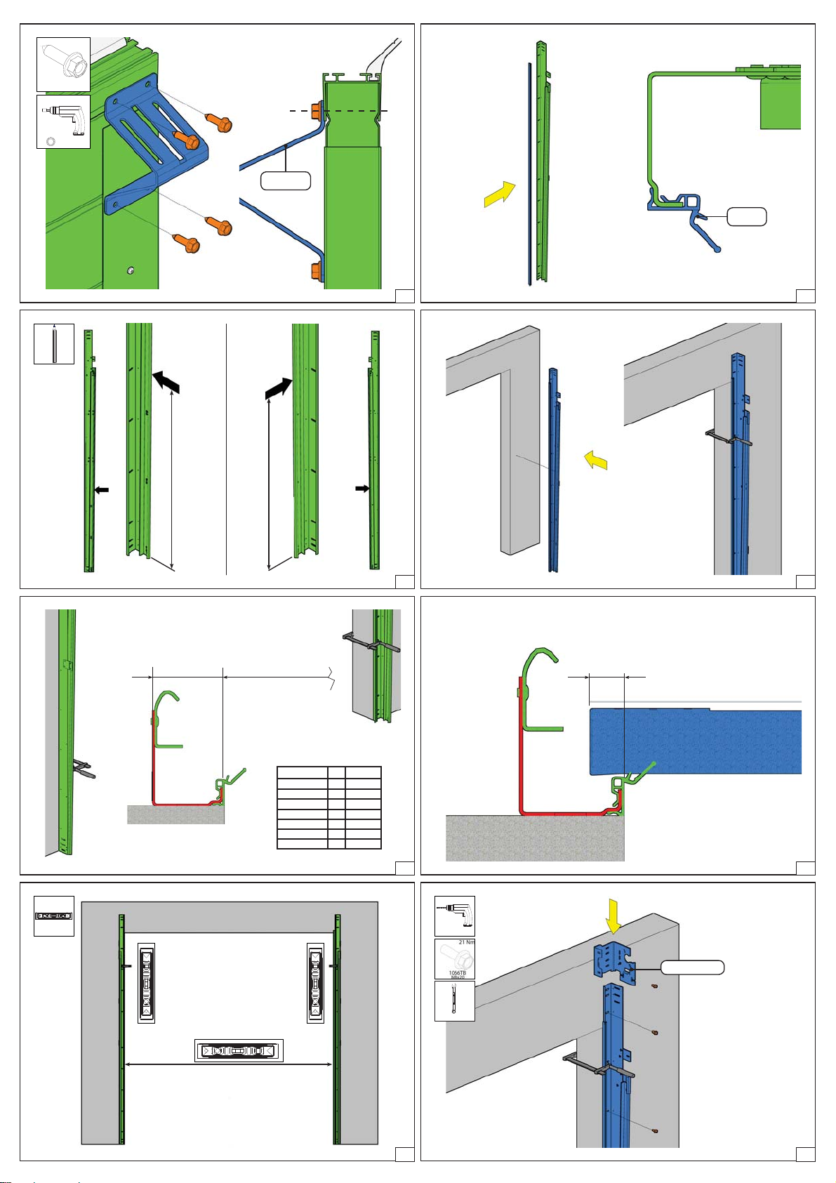
%)
0[
1P
1062M
M6
1P
:)
%)
0[
1P
M8
1068M
:)
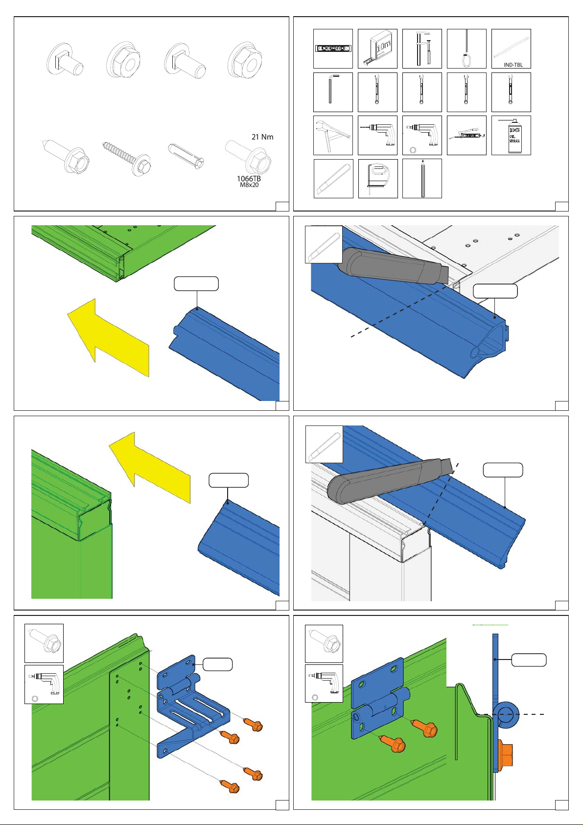
1055BV
or other
10 Nm
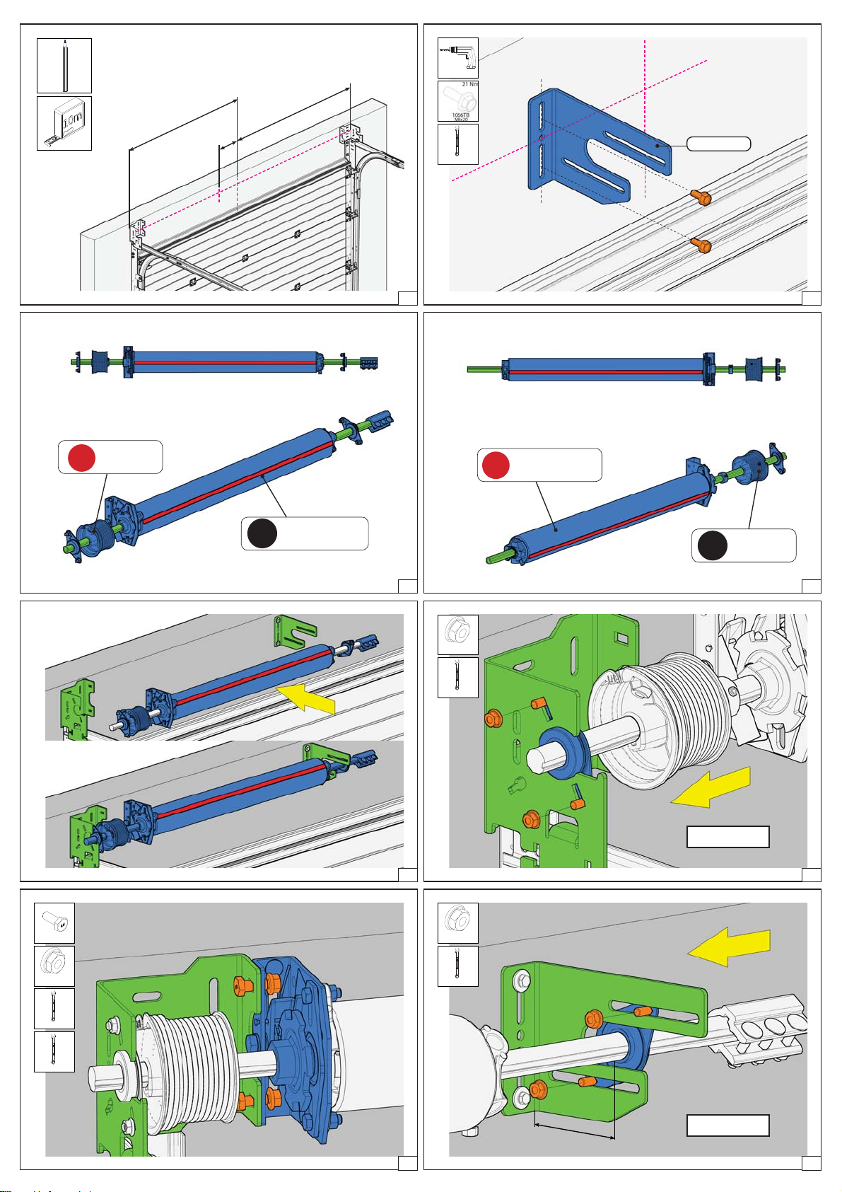
01 161 991rev. 28-07-2017 1
PP PPPP
PPP PP
15 mm 24 mm
01 161 991rev. 28-07-2017 2
1039-55
106B1-7
1039-52
01 161 991rev. 28-07-2017 3
1039-55
106B1-8
1039-52
01 161 991rev. 28-07-2017 4
1036
106C1-1
1036-36
01 161 991rev. 28-07-2017 5
1036
106C1-2
1036-36
01 161 991rev. 28-07-2017 6
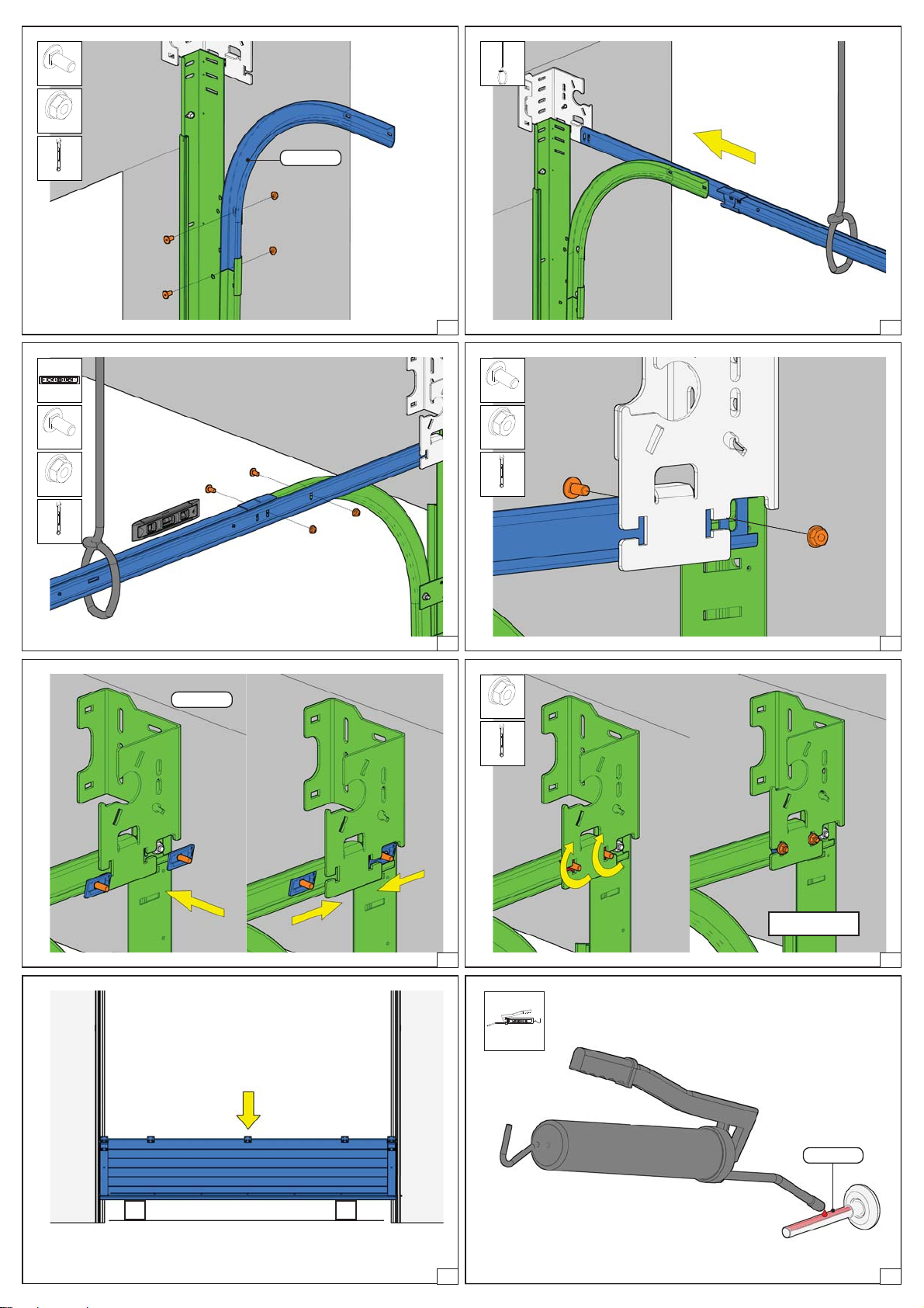
1055BV
or other
10 Nm
PP
450CZ
106I1-1
1055BV
or other
10 Nm
PP
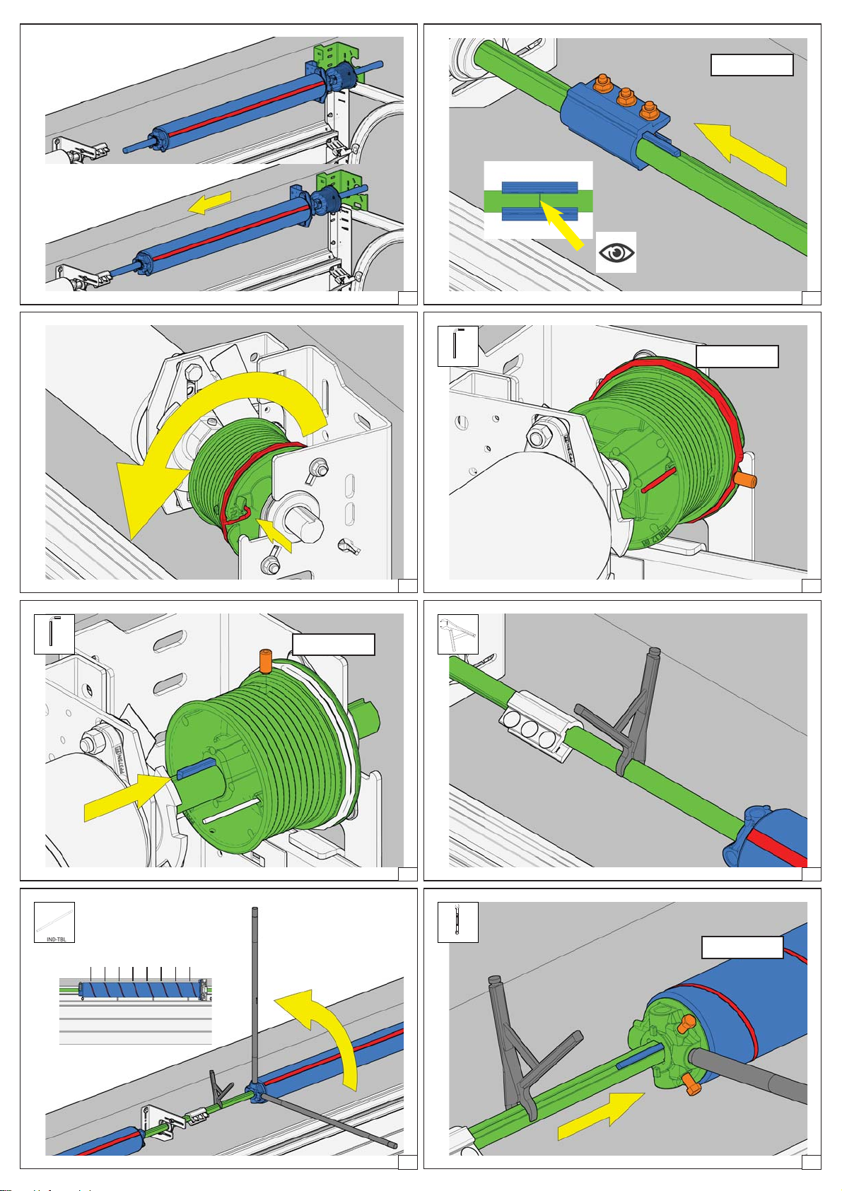
01 161 991rev. 28-07-2017 7
1055BV
or other
10 Nm
PP
415HZ
01 161 991rev. 28-07-2017 8
1055BV
or other
10 Nm
PP
415CZ
01 161 991rev. 28-07-2017 9
1088I
01 161 991rev. 28-07-2017 10
B
1000
A
1000
01 161 991rev. 28-07-2017 11 01 161 991rev. 28-07-2017 12
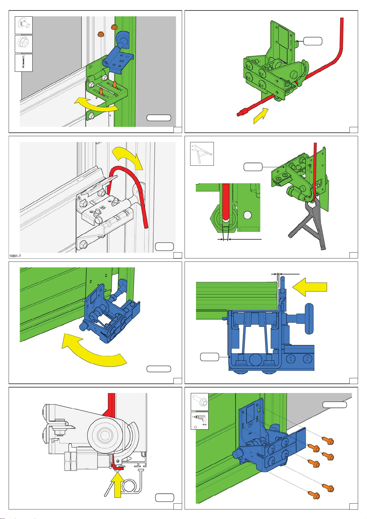
X OPW
440S
440HD
440REGL
Type XZ
425HD
427SX
428TAI
429
75
70
72
64
74
75
76
2066-10
2066-10
-
-
-
-
-
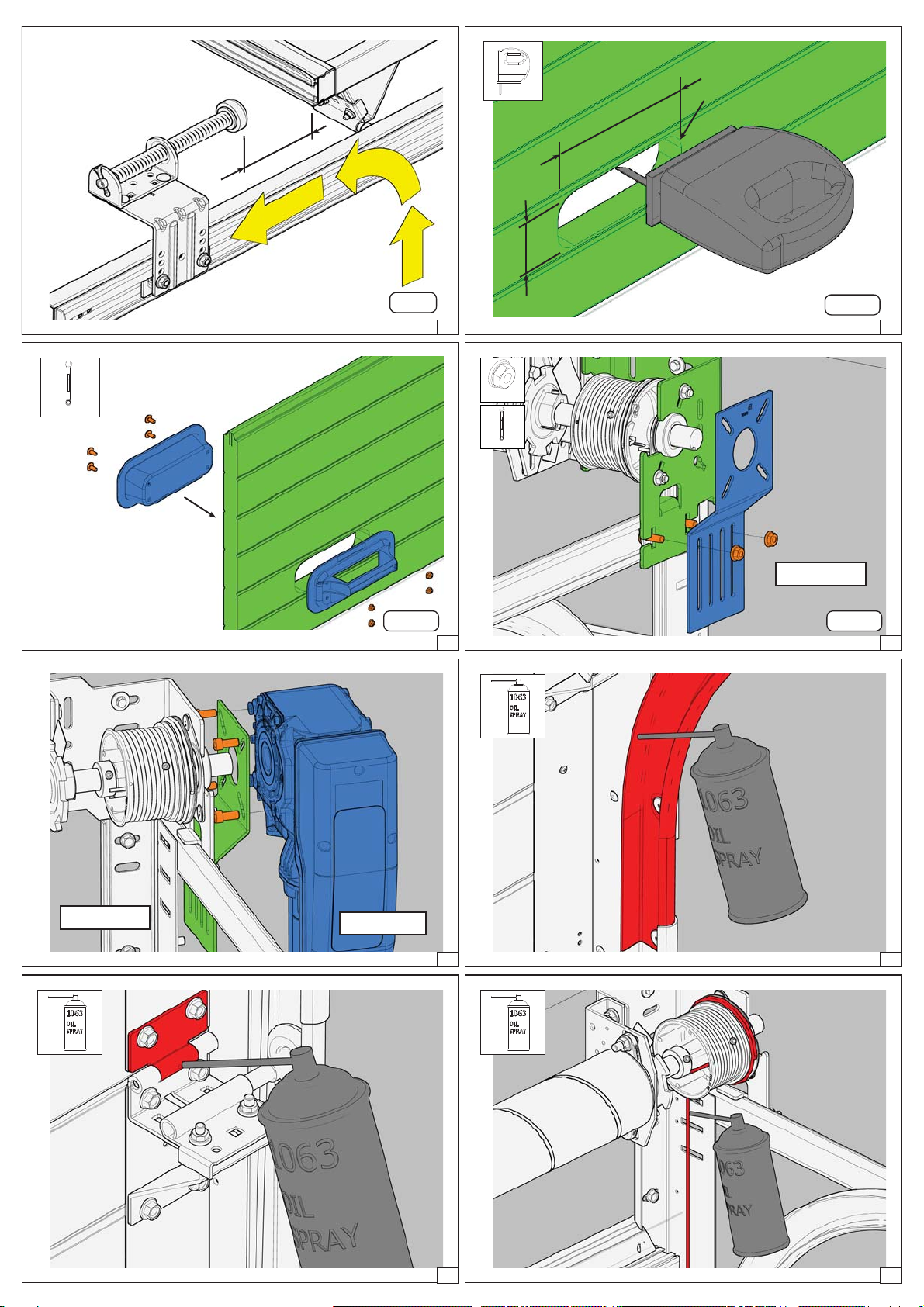
01 161 991rev. 28-07-2017 13
22,5
01 161 991rev. 28-07-2017 14
B
A
01 161 991rev. 28-07-2017 15
P7,3 mm
PP
3111FR/L
01 161 991rev. 28-07-2017 16
%)
0[
1P
PP
M8
1068M
2G380A0
01 161 991rev. 28-07-2017 17 01 161 991rev. 28-07-2017 18
%)
0[
1P
PP
M8
1068M
01 161 991rev. 28-07-2017 19
%)
0[
1P
PP
M8
1068M
01 161 991rev. 28-07-2017 20
1026N1B
01 161 991rev. 28-07-2017 21
PP
M8
1068M
23 Nm
01 161 991rev. 28-07-2017 22
106A-
18 01 161 991rev. 28-07-2017 23 106A-
17
All types
01 161 991rev. 28-07-2017 24
%)
0[
1P
PP
1062M
M6
450CZ
01 161 991rev. 28-07-2017 25
440S
106M1-101 161 991rev. 28-07-2017 26
450CZ
01 161 991rev. 28-07-2017 27
Cable -1mm
440S
106M1-201 161 991rev. 28-07-2017 28
440S
01 161 991rev. 28-07-2017 29
440S
0,5 mm
106M1-601 161 991rev. 28-07-2017 30
440S
106M1-501 161 991rev. 28-07-2017 31
1055BV
or other
10 Nm
PP
440S
01 161 991rev. 28-07-2017 32
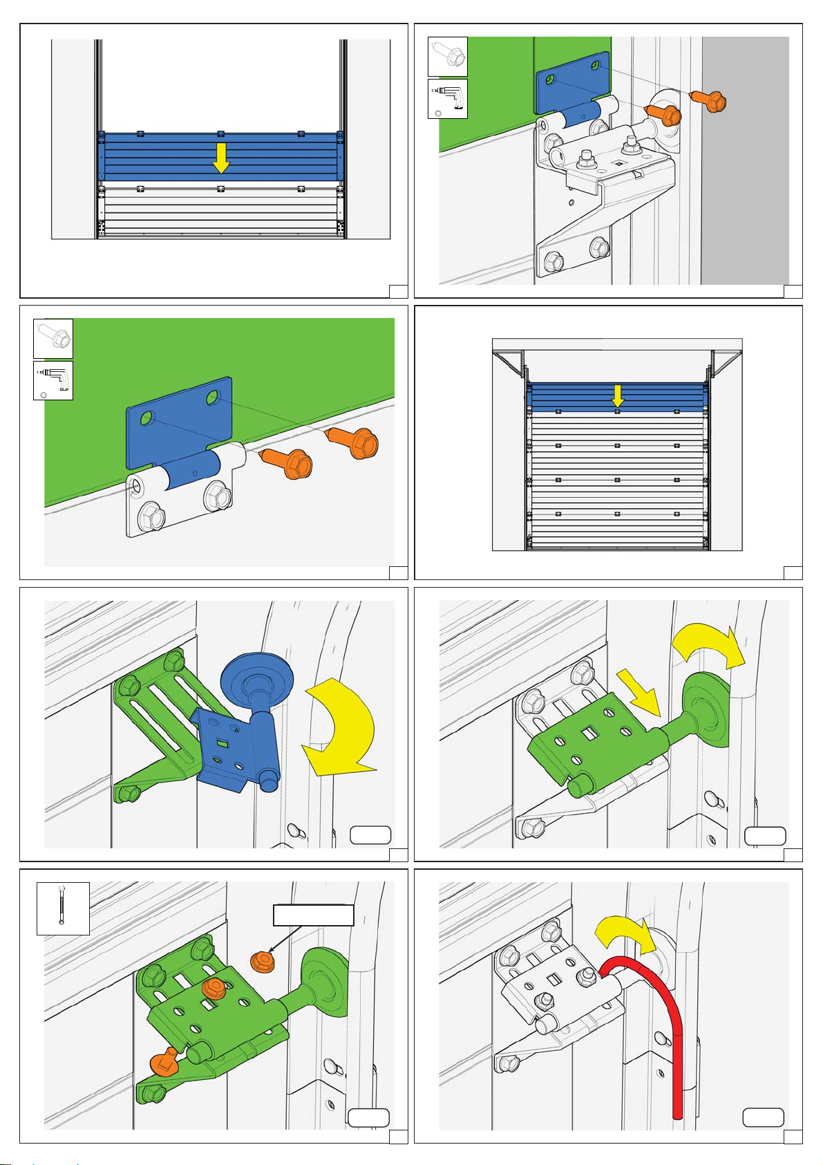
106A-
19 01 161 991rev. 28-07-2017 33
1055BV
or other
10 Nm
PP
01 161 991rev. 28-07-2017 34
1055BV
or other
10 Nm
PP
01 161 991rev. 28-07-2017 35 106A-
20 01 161 991rev. 28-07-2017 36
415CZ
106D1-11 01 161 991rev. 28-07-2017 37
415CZ
106D1-12
415CZ
01 161 991rev. 28-07-2017 38
PP 6Nm
415CZ
106D1-13
415CZ
9 Nm
01 161 991rev. 28-07-2017 39
415CZ
106D1-14
415CZ
01 161 991rev. 28-07-2017 40
==
125
01 161 991rev. 28-07-2017 41
USA8R/L
P7,3 mm
PP
01 161 991rev. 28-07-2017 42
/ LH
/ LHW
01 161 991rev. 28-07-2017 43
/ RH
/ RHW
01 161 991rev. 28-07-2017 44
01 161 991rev. 28-07-2017 45
23 Nm
PP
M8
1068M
01 161 991rev. 28-07-2017 46
%
0[
1P
15 mm
M10
1058F
17 mm
01 161 991rev. 28-07-2017 47
PP
M8
1068M
23 Nm
HOH
01 161 991rev. 28-07-2017 48
01 161 991rev. 28-07-2017 49
35 Nm
01 161 991rev. 28-07-2017 50
01 161 991rev. 28-07-2017 51
15 Nm
PPPP
01 161 991rev. 28-07-2017 52
15 Nm
PP
01 161 991rev. 28-07-2017 53 01 161 991rev. 28-07-2017 54
1 2 3 4 5 6 .. ..
01 161 991rev. 28-07-2017 55
PP 20 Nm
01 161 991rev. 28-07-2017 56

15 Nm
PP
01 161 991rev. 28-07-2017 57
15 Nm
PP
01 161 991rev. 28-07-2017 58
440S
106M1-901 161 991rev. 28-07-2017 59
24 mm
01 161 991rev. 28-07-2017 60
24 mm
15 Nm
01 161 991rev. 28-07-2017 61
440S
106M1-13 01 161 991rev. 28-07-2017 62
1/2
01 161 991rev. 28-07-2017 63
=
=
01 161 991rev. 28-07-2017 64

OPH
018<NN>
01))-<NN>
01 161 991rev. 28-07-2017 65
40B25
50BH30
30B20
106J2-101 161 991 rev. 28-07-2017 66
M8x25
23 Nm
1070B35
M8
1068M
PP
106J2-201 161 991 rev. 28-07-2017 67
1026N1B
M8
1068M
PP
106J2-301 161 991 rev. 28-07-2017 68
106J2-4
:)
PPP
1P
:)
PP
01 161 991rev. 28-07-2017 69
718C
106J1-5
PP
01 161 991rev. 28-07-2017 70
718C
106J1-6
1027N7B
PP
M8
1068M
01 161 991rev. 28-07-2017 71
718C
106J1-701 161 991 rev. 28-07-2017 72
718C
± 50 mm
106J1-8
01 161 991rev. 28-07-2017 73
220
85
R20 (4x)
106A3-7
640T
01 161 991rev. 28-07-2017 74
PP
106A3-8
640T
01 161 991rev. 28-07-2017 75
300PB
PP
M8
1068M
23 Nm
01 161 991rev. 28-07-2017 76
OPTION
23 Nm
01 161 991rev. 28-07-2017 77 01 161 991rev. 28-07-2017 78
01 161 991rev. 28-07-2017 79 01 161 991rev. 28-07-2017 80
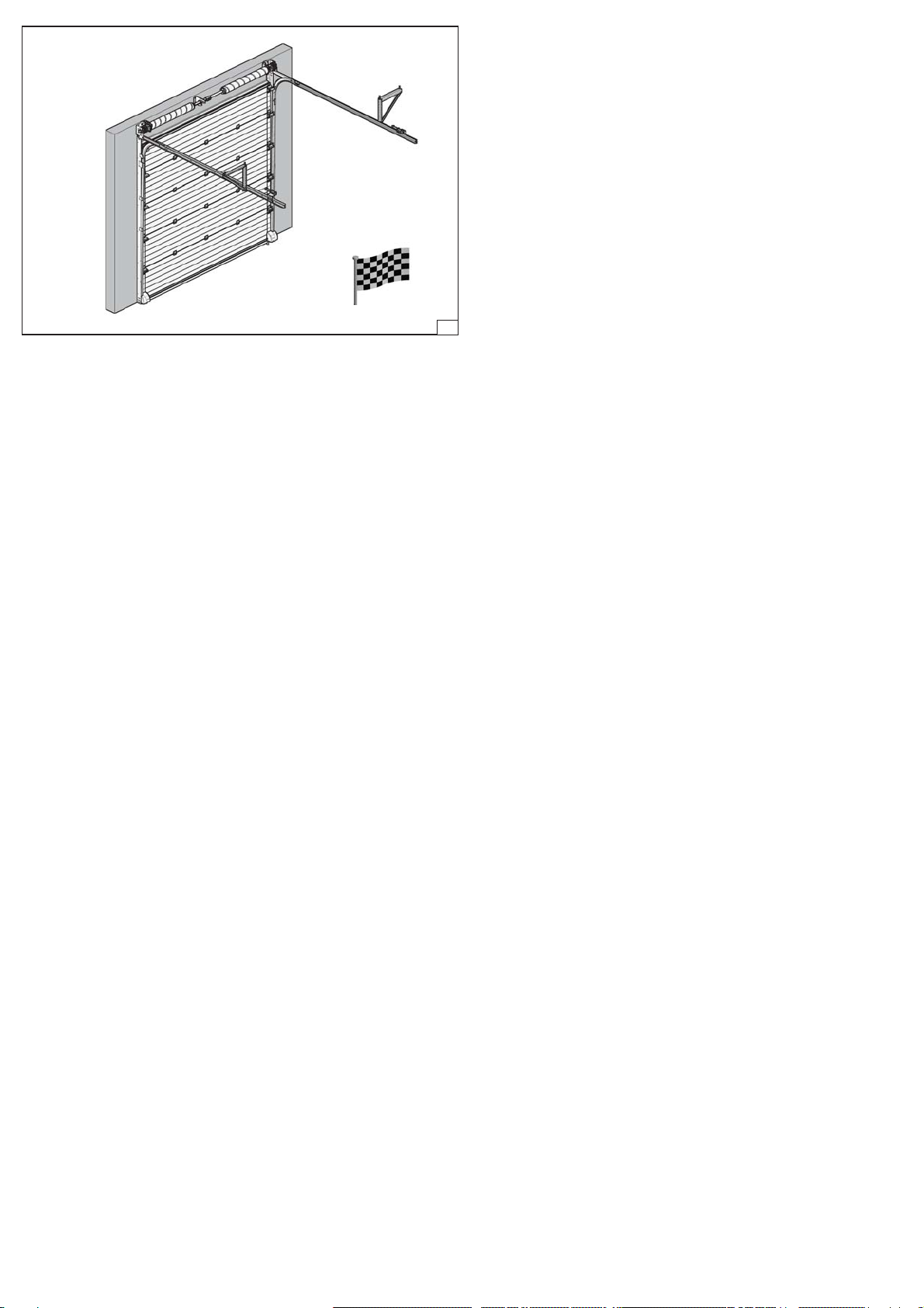
01 161 991rev. 28-07-2017 81
Other FlexiForce Door Opening System manuals


Popular Door Opening System manuals by other brands


Hafele
Hafele 940.41.043 Installation instructions operating instructions

Entrematic
Entrematic DITEC LUXO-E2 quick reference

Green Star
Green Star Touch 'n Hold Smooth installation instructions

Entrematic
Entrematic EM EMSW Installation and service manual

Entrematic
Entrematic Ditec OBBI manual

Green Brook
Green Brook DW030A quick start guide


