manuals.online logo
Brands
  1. Home
  2. •
  3. Brands
  4. •
  5. Erreka
  6. •
  7. Door Opening System
  8. •
  9. Erreka VIVO-M101M Operating instructions

Erreka VIVO-M101M Operating instructions

5
VIVO-M101(M)
Quick installation and programming guide English
IMPORTANT
NOTE
This quick guide summarises the full installation manual. The full manual contains safety warnings and other
explanations that must be taken into account. You can download the latest version of this guide and the
installation manual in the "Downloads" section of the Erreka website:
http://www.erreka-automation.com
The options and functions described in this guide are applicable from the firmware version indicated on the
circuit. As part of a process of continuous improvement, the firmware is subject to the incorporation of new
functionalities or their extension, and consequently to the generation of new versions not necessarily
compatible with the previous ones. Therefore, if your firmware version is lower than the one indicated in
this guide, some options and functions may not be available or may be different.
E175A
ELECTRICAL CABLING:
Element Nº wires x section Maximum length
A: Main power supply 3x1.5mm230m
B: Flashing light 2x0.5mm220m
C: Photocells (Tx / Rx) 2x0.5mm2/ 4x0.5mm230m
D: Pushbutton/wall key 2x0.5mm225m
E: Operator / Limit switches 4x0.75mm2 / 4x0.50mm220m
F: Antenna Coaxial cable 50k(RG-58/U) 5m
Elements of the complete installation
MSA-097/03 firmware V2.00 or later
6
DL1
DL14
DL17
F2
DL13
DL15
F3
F1
DL8
DL7
DL6
DL11
DL9
DL10
DL12
General connections
Turning direction: check operation using the
mini-pushbuttons PUL1 (close) and PUL2 (open).
If the turning direction of the operator is not
correct, interchange the cables connected in
cable connectors G1 and G2.
Operator
connections A:
G1 open
G2 close
G3 common,
grey
T: earth
connection
•When pressing PUL1 (close), DL5 lights up
and the G2 and G3 cable connectors of the
operator are enabled.
•When pressing PUL2 (open), DL4 lights up
and the G1 and G3 cable connectors of the
operator are enabled.
VIVO-M101:
230Vac/50Hz
VIVO-M101M:
125Vac/60Hz
DEST. (max. 40W)
VIVO-M101: 230Vac
VIVO-M101M: 125Vac
LG
VIVO-M101: 230Vac, max 2,300W
(resistive)
VIVO-M101M: 125Vac, max 1,250W
(resistive)
VIVO-M101: 230Vac
VIVO-M101M: 125Vac
PUL1: close mini-pushbutton
PUL2: open mini-pushbutton
DL1 Gate totally or partially open
DL1 - DL3 flashing: STOP contact
open (emergency stop
activated)
DL2 Receiving RSD plug-in receiver
radio signal (RUN/OK)
DL3 Radio code or operation
programming
DL4 Opening relay activated
DL5 Closing relay activated
DL6 Interior safety device contacts
(FT2) closed
DL7 FCA contacts closed
DL8 FCC contacts closed
DL9 Exterior safety device contacts
(FT1) closed
DL10 Pedestrian key command (ST2)
DL11 Total key command (ST1)
DL12 Plug-in receiver key command
(except RSD)
DL13 Garage light relay activated
DL14 Power supply
DL15 Electrolock relay activated
DL17 Triac M1 activated
Fuses:
F1 M1 Motor fuse
– M101: 2,5A (230Vac/50Hz)
– M101M: 6,3A (125Vac/60Hz)
F2 Electronic fuse
– M101: 0,5A (230Vac/50Hz)
– M101M: 1A (125Vac/60Hz)
F3 Output fuse 24Vac (315mA)
DIP1=ON: programming enabled (DL3 lights up)
DIP1=ON and DIP2=ON: total open/close programming
DIP1=ON and DIP3=ON: pedestrian open/close programming
DIP1=ON and DIP4=ON: total opening radio code programming
DIP1=ON and DIP6=ON: pedestrian opening radio code programming
SW2 Functions during programming (DIP1=ON)
7
*: If hydraulic operators with absorbers are used, soft stop is carried out mechanically by the operator (DIP8 = OFF)
Using radio cards
This control board is factory set to use a two-channel receiver (e.g. IRRE2). This factory setting is modified if an RSD receiver is used and a
permanent code is recorded (decoding through the board, DIP1 + DIP4 or DIP6 = ON). To recover the factory settings, insert the IRRE2 card
and place DIP1 + DIP4 or DIP6 = ON. Then return the DIPs to their previous position.
Total opening radio code programming (with RSD receiver only)
If a receiver other than RSD is used,
see the corresponding instructions.
1 Connect the electrical power
supply and close the leaf, keeping
PUL1 pressed down.
2 Select the code in the transmitter.
3 Place the DIPs as shown in the
figure (DIP1=ON, DIP4=ON). DL3
lights up to show programming mode
enabled.
4 Press the button of the required
channel. DL2 flashes to show
programming is complete.
5 Place DIP1 and DIP4 in OFF.
DL3 remains off.
6 Disconnect and reconnect the
electrical power supply.
Programming is carried out in the
same way, using DIP6 instead of DIP4.
R175B
R175
K
Pedestrian opening radio
code
Total open/close programming
1 Connect the electrical power supply
and close the leaf, keeping PUL1
pressed down.
2 Place DIP1 in ON, DIP2 in ON, DIP5
in ON (only with electrolock), DIP8 in
ON (soft stop)*.
DL3 lights up (programming enabled).
3 Press ST1 to start opening the leaf.
4 Press ST1 to start soft stop (with
DIP8=ON only).
5 Press ST1 to finish opening (if FCA
is installed, it is not necessary to press
ST1).
6 Press ST1 to start closing the leaf
7 Press ST1 to start soft stop (with
DIP8=ON only).
8 Press ST1 to finish closing (if FCC is
installed, it is not necessary to press
ST1).
9 Place DIP1 and DIP2 in OFF. DL3
remains off.
Pedestrian open/close programming
This is carried out in the same way as total open/close
programming, with the following differences:
•DIP1 and DIP3 are used instead of DIP1 and DIP2
•ST2 is used instead of ST1
8
DIP Modes and functions Option Effect
DIP1 OFF
DIP2 Advance warning ON the flashing light comes on and the operation begins after a 3 second
warning
OFF the flashing light comes on and the operation begins immediately
DIP3 Opening mode
ON step-by-step opening (the gate halts if a key device is enabled
during opening, and closes if enabled again)
OFF collective opening (the control board does not obey the key
commands during opening)
DIP4 Automatic or step-by-step mode
(for pedestrian and total operation)
ON
automatic mode (the gate closes automatically after standby time
has passed, which is adjusted using T.E.). Standby time restarts if the
photocell is enabled.
OFF step-by-step mode (the gate only closes when receiving the key
command)
DIP5 Reverse impulse /
close impulse
ON recede impulse enabled. If soft stop is selected (DIP8=ON), a close
impulse is also carried out
OFF close and recede impulse disabled
DIP6 Automatic mode optional
(only if DIP4 = ON)
ON during standby, the gate obeys the key commands (can be closed
before standby time finishes)
OFF the gate cannot be closed until standby time finishes; a key command
will cause standby time to restart
DIP7 Maintaining hydraulic pressure
(for hydraulic operators only)
ON every two hours it carries out a close impulse in order to maintain
hydraulic pressure
OFF maintain pressure disabled
DIP8 Soft stop (only for operators
without mechanical absorber)
ON the leaves reduce their speed before reaching the stopper
OFF the leaves reach the stopper at high speed
DIP9
Anti-crushing function (obstacle
detection); the obstacles are only
detected when the gate has come
to a complete halt.
ON
Function activated: during quick travel, the gate detects obstacles
upon collision and recedes (when soft stop is activated, DIP8 = ON) or
remains shut down (when soft stop is disabled, DIP8 = OFF) in order
to prevent crushing
OFF Function disabled
DIP10
Dead man function
Only with DIP4=OFF and
DIP11=OFF
ON Dead man function enabled (opening is done by keeping ST1 pressed
down; closing is done by keeping ST2 pressed down)
OFF Dead man function disabled
DIP11 Interlock mode
Only with DIP4=ON
ON DIP10=ON: interlock mode with exterior and interior photocells
DIP10=OFF: interlock mode with exterior photocell
OFF Interlock mode disabled
DIP12 Safety device ON VULCAN S safety device connected in the FCA cable connectors
OFF Device not connected
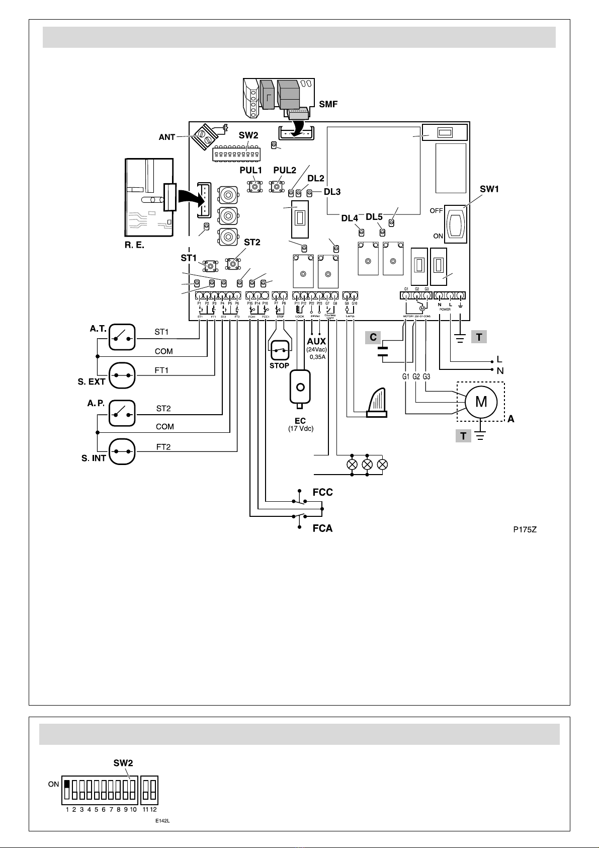
Function and mode selection using SW2 (DIP1 = OFF)
ST1
FT1
P1 P2 P3
ST2
FT2
P4 P5 P6
STOP
P7 P8 P11
P12
LOCK
FCA1
FCC1
P15 P14 P16
P22
P
24V
a
P175M
Potentiometer adjustment
T.LG (garage light time): If the garage lighting circuit has been connected to
the control board, set the time which the lights shall remain on using T.LG.
T.E. (gate open standby time): if automatic functioning mode has been
programmed (DIP4=ON), set T.E. to adjust standby time with the gate open
(before automatic closing begins).
P.M (motor torque): use P.M. to adjust the maximum operator power value.
•Hydraulic operators: set P.M. at the maximum value.
•Electromechanical Actuators (anti-crushing function sensitivity): set P.M at
the minimum value possible, compatible with the proper operation of the
gate.
Adjust the torque to respect the maximum closing thrusts set out in
Standard EN12453:2000. Make the measurements as described in
Standard EN 12445:2000.

This manual suits for next models

2

Other Erreka Door Opening System manuals

Erreka RINO-I Operating instructions

Erreka

Erreka RINO-I Operating instructions

Erreka VIVO-M101 Operating instructions

Erreka

Erreka VIVO-M101 Operating instructions

Erreka VIVO-D103 Operating instructions

Erreka

Erreka VIVO-D103 Operating instructions

Erreka PREMIS 200 User manual

Erreka

Erreka PREMIS 200 User manual

Erreka Premis PREMIS200 Operating instructions

Erreka

Erreka Premis PREMIS200 Operating instructions

Popular Door Opening System manuals by other brands

GEZE GC 342+ user guide

GEZE

GEZE GC 342+ user guide

GEM AD500 instruction manual

GEM

GEM AD500 instruction manual

Assa Abloy SARGENT 1130-HU Series installation instructions

Assa Abloy

Assa Abloy SARGENT 1130-HU Series installation instructions

Automatic Technology GDO-6 EasyRoller Quick operation guide

Automatic Technology

Automatic Technology GDO-6 EasyRoller Quick operation guide

Manaras Opera EYLESSO42 user manual

Manaras Opera

Manaras Opera EYLESSO42 user manual

Canaropa 4000CNS Series installation instructions

Canaropa

Canaropa 4000CNS Series installation instructions

TOPP S200 Instructions for installation and use

TOPP

TOPP S200 Instructions for installation and use

Label Neptis SLT-B user manual

Label

Label Neptis SLT-B user manual

Entrematic Ditec VALLOK installation manual

Entrematic

Entrematic Ditec VALLOK installation manual

Yale 7000 Series parts manual

Yale

Yale 7000 Series parts manual

B&D PanelMax SDO-8 installation instructions

B&D

B&D PanelMax SDO-8 installation instructions

GEZE FA GC 150 Wiring diagram

GEZE

GEZE FA GC 150 Wiring diagram

Dorma ES 200 Easy Mounting instruction

Dorma

Dorma ES 200 Easy Mounting instruction

DoorHan PCB-SW Programming instructions

DoorHan

DoorHan PCB-SW Programming instructions

Dorma UNIVERSAL Motion Mounting instructions

Dorma

Dorma UNIVERSAL Motion Mounting instructions

Dorma ES 200 manual

Dorma

Dorma ES 200 manual

Assa Abloy SECURITRON DEM680E Series Installation & operating instructions

Assa Abloy

Assa Abloy SECURITRON DEM680E Series Installation & operating instructions

Siemens SIRIUS 3RV19 6 2 Series operating instructions

Siemens

Siemens SIRIUS 3RV19 6 2 Series operating instructions

manuals.online logo
manuals.online logoBrands
  • About & Mission
  • Contact us
  • Privacy Policy
  • Terms and Conditions

Copyright 2025 Manuals.Online. All Rights Reserved.