FlexiForce CE-LHR User manual

manual NL
handleiding IND www.flexiforce.com
GB
NL
User manual
industrial overhead doors
© All rights reserved. FlexiForce® 2006
manual multilanguage
manual
FF-MANUAL CE-LHR /1 WWW.FLEXIFORCE.COM
GB
(patent pending)
installation manual
INDUSTRIAL
hardware set for low
headroom overhead
doors (CE-LHR)
max. w = 5,0m
max. h = 5,0m
max. kg = 300kg
CE-LHR, CE-FLH
©All rights reserved. Flexi-Force BV
2006
manual
FF-MANUAL CE-LHR /2 WWW.FLEXIFORCE.COM
GB
ATTENTION! GENERAL WARNINGS!
To install, use and maintain this door safely, a number of precautions must be
taken. For the safety of all concerned pay heed to the warnings and
instructions given below! If in doubt, contact your supplier.
9SPECIAL SAFETY WARNI NGS OR RE MARKS IN THIS MANUAL ARE INDI CATED
WITH THIS SYMBOL: READ THESE WARNINGS CAREFULLY.
9This manual has been written for use by experienced fitters and as su ch is not
suitable for d.i.y. purposes or for use by trainee fitters.
9This manual describes the installation of the hardware set components, door
sections (panels) and r efers to installa tion manuals of the electri cal operators. Be
sure to supplement this manual if needed with instruction s for an y additional
components not described in this manual.
9Before starting, read this manual carefully!
9Certain components may be sharp or have jagged edges. As such you are ad vised to
wear safety gloves.
9All the components which have been supplied are designed for use with this spec ific
overhead door. Replacement or adding additional components may have an adverse
effect on the safety of, and the guarantee on, the door. Also th e CE-approval which
has been granted to this door co mbination will be cancelled wh en components are
changed or installation is not done according to this manual! Installer is respon sible
for this.
9During tensioning, springs can exert l arge forces. Work carefully. Use the proper
equipment. Ensure that you are standing in a steady position.
9Ensure that t here is suffici ent light duri ng installation. Remo ve obstacles and dirt.
Make sure that there is no one else p resent other than the fitte rs. Other p eople
(children!) may get in the way or endanger themselves during the installation.
9Ensure that the building is constru cted strong enough to carry the overhead door
construction. It is the respo nsibility of the installing company to use fixing material s
which are strong enough and equipped to fix the overhead door to the building.
9A power operated o verhead door may not be equipped with a pull cord (rope). Be
sure that this has been removed when a manual operated door is being equipped with
an E-operator.
9Environments closed by an electrical operated overhead door with operators which
are not disconnectable and where the door cannot be manual o perated must be
equipped with a pass door.
9Cutting of the bottom secti on is not allo wed. The forces on cable break devices and
bottom brackets are too high. Cutting is we akening the construction of the door on
this critical point. If you need to cut the bottom section make sure you can guarantee
the strength.
This door can only be taken into use, when all instructions are followed and:
9the installer has checked the combination of hardware, panel and e-operator as
being approved and saf e. Make sure to chec k the m ax. peak force and the proper
functioning of the safety edge system in combination with the operator.
9all documentation has b een handed over to the end-user: II a Declaration of
conformity, User Guide, Main tenance Instructions, Dismantling instructions, Service
Log Book and this manual.
9a CE-identification plate has been placed on the door.
9user has b een given instructions and demonstration of the proper use and
functioning of the door.
manual
FF-MANUAL CE-LHR /3 WWW.FLEXIFORCE.COM
GB
GUARANTEE, CONDITIONS AND TERMS
The general terms and conditions of delivery and payment issued by the Metaalunie and designated as
METAALUNIE CONDITIONS are fully applicable to all our quotations, contracts and their implementation.
We expressly reject all other terms and conditions. On request we will send you a copy of these terms and
conditions free of charge. A copy may also be downloaded from our website www.flexiforce.nl.
Flexi-Force strives to deliver 100 % in conformance with the order. In practice, in spite of all our controls, this is
not always possible. However we will rectify any errors as quickly as possible, in order to minimise the
inconvenience caused to you or the user. As such, it is important that you inform us as soon as possible about
any problem with the delivery (include the order number and week of production) and give us the opportunityto
offer a suitable solution.
Flexi-Force will only reimburse third party costs if we have given explicit permission for this in advance. The
reimbursement is based onnormal rates andtravelling expenses over distances of 1 hour away at most.
For large-scale projects we strongly advise you to first install 1 door completely before installing the other doors.
In this way, any errors can be detected early on and rectified comparatively cheaply.
This manualdoes not confer any rights. Technical modifications may be made without written notice.
Flexi-Force has endeavoured to design and put together this hardware set in conformance with the applicable
CE-norms.However,we recommend tocheck our configurationagainst any local national specification.
Flexi-Force B.V., P.O. Box 37, 3770 AA Barneveld, The Netherlands
Tel. +31-(0)342-427777, [email protected]
APPLICABLE CE DIRECTIVES AND RESTRICTIONS:
Industrial overhead doors brought into the European market must follow the EMC-Directive*, Low Voltage
Directive*, Machine Directive* and Construction Products Directive, issued by CEN.
(* = only power-operated doors)
Flexi-Force has developed and constructed this hardware set according to these directives. This gives a
restriction to the max. forces and dimensions of industrial doors:
•Max width : 5 meter
•Max height : 5 meter
•Max door weight : 300 kg
•Standard equipped with anti-drop protection: Cable break device a nd spring breaking
device
•Other safety accessories: roller protection, bottom safety edge system (whe n power
operated), slack cable device, cable inside track system.
•Tested for CE when selecting the proper Flexi-Force components, and c ombining with
tested panels and operator/control unit combinations.
•Use of finger safe sections for door heights <2,75m.
•Cables outside the track system are not allowed, unless the cables are covered.
Flexi-Force has applied the mandated INITIAL TYPE TESTING for doors described in this manual, at
the SP-Institute in Sweden (as Notified Body Nr. 0402). The INITIAL TYPE TESTING REPORT that
has been rewarded, can be transferred to the door producing company when truly declared
conformity is done. This is needed to complete your CE technical construction file according to
product standard EN13241-1. The ITTR-number should be placed on the CE-plate on the door.
The article codes of the parts are given in (parentheses). This door can only be installed according to the
CE-certificate if all parts are according to the parts lists of the SP-certificate. See www.flexiforce.com.
This manual should be completed with additional installation manuals for IND Hardware sets, cable break
devices, spring break devices and E-operator.

manual
FF-MANUAL CE-LHR /4 WWW.FLEXIFORCE.COM
GB
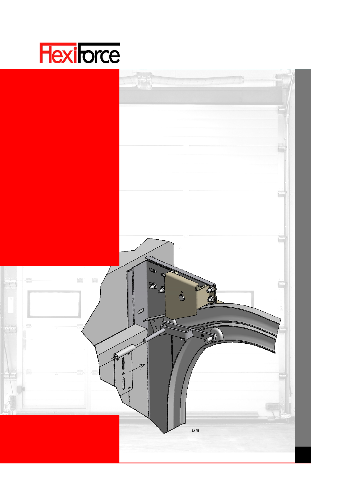
SYSTEM DESCRIPTION
The system is really simple. First of all the needed head room: minimal 205mm!
To achieve this we have designed a special curve assembly, 567-554-2GD. It contains a special lower curve (A),
with a “double radius”. This curve is cut and welded resulting in a “sharper” curve. The upper curve (B) runs just
under the cable pulley system (C). This system consists of a cable pulley mounted and secured to the side plate
through a top pulley plate. This part of the system is supplied to you completely pre-assembled.
The cable runs through the new designed, fork-shaped roller (D), article code 593, through the track and is finally
connected to the cable break device, article code 440-LHR. To create the space needed for the cable, a different
type of vertical angle is used, code 9K…(E). The distance between panel and track is bigger compared to other lift
systems. Therefore the rollers need to have a longer shaft as well, article code 575LHR and 575-304LHR (stainless
steel).
A
A
B
C
D
DE

manual
FF-MANUAL CE-LHR /5 WWW.FLEXIFORCE.COM
GB
Available lift systems:
•LHR = Low Head Room
•FLH = Following the roof Low Head room (CE-FLH) with angles in steps of 5 degrees (max 28º).
A special tension set has been designed for combining with this new system. Article code 688CR/L. See attached
build-in instructions.
BUILD-IN SPECIFICATIONS
Minimum build in height 40
mm panel.
no 6" springs 6" springs
FF-NL-12, FF-NL-18
no tension set 688CR 205 mm 215 mm
with tension set 688CR 230 mm 230 mm
FF-NL-32 240 mm 240 mm
The system is suitable for panel thickness between 40 and 50 mm. For thicker panels than 40
mm the build in height will increase.
Needed side room
no tension set 688CR 120 mm
with tension set 688CR 145 mm
INSTALLATION OF TRACK SYSTEM
Distinguishing feature
With CE-LHR systems the door turns through the bend directly above the clear height. The horizontal section
consists of a double track. See figure.
Tracks
The track system of the LHR System consists of a vertical and a horizontal section.

manual
FF-MANUAL CE-LHR /6 WWW.FLEXIFORCE.COM
GB
Vertical track set
This is made up of a left-hand and right-hand assembled vertical angles (9K) with track and side seal.
Horizontal track set
The horizontal track set consists of a left-hand and right-hand section with a double bend, straight tracks and a
reinforcement profile. The bends and the straight guide tracks are fitted to each other by connection plates and a
side plate. The side plate is fitted with a return pulley system. The side plate is supplied pre-assembled.
Assembly vertical track set
Slide the side seal onto the corner line and shorten this where necessary. Secure the vertical track set level to the
pendent.
Ensure that the side seal cannot be displaced. When necessary deform the rim of the corner line above the side
seal.
Assembly horizontal track set
Secureapieceofropetotheceilingorroofstructure.Adjustthehorizontaltrack.Tightenallbolts.
OtherinstructionscanbefoundinthegeneralInstallationManualofourindustrialhardwaresets.
WARNING: IN CASE OF INSTALLING THE HORIZONTAL TRACK SET ON HORIZONTAL LEVEL A 688CR
CABLE TENSION SET MUST BE INSTALLED TO PREVENT SLACK CABLES. ONLY WHEN THE SHAFT IS
DIRECTLY ACTIVATED (CHAIN HOIST OR OPERATOR).
OTHER REMARKS
•On doors with small heights locks must be installed at height less than 700 mm. Otherwise the lock bar
will hit the cable.
•Shape of bottom rubber most be so that it does not hit the side seal when opening the door.
•Length of horizontal track on LHR is standard based on mounting a tension set even if it is not part of the
delivery.
•When ordered “double hardware” the standard top roller construction for single hardware is supplied.
LIST OF PRODUCTS SPECIAL FOR CE-LHR
Article code Description
567-554-2GD Side plate curve assembly LHR
567-554-2GD-05/28 Side plate curve assembly FLH 5º / ../../../28º
593 Top roller
575LHR Roller
575-304LHR Roller, stainless steel
440LHR Cable break device LHR
9K4500 Vertical angle
9K6500 Vertical angle
688CR Tension set LHR right
2090L Bracket for spring bumper
632L Slide bolt with longer rod
669S Cylinder lock
manual
FF-MANUAL CE-LHR /7 WWW.FLEXIFORCE.COM
GB
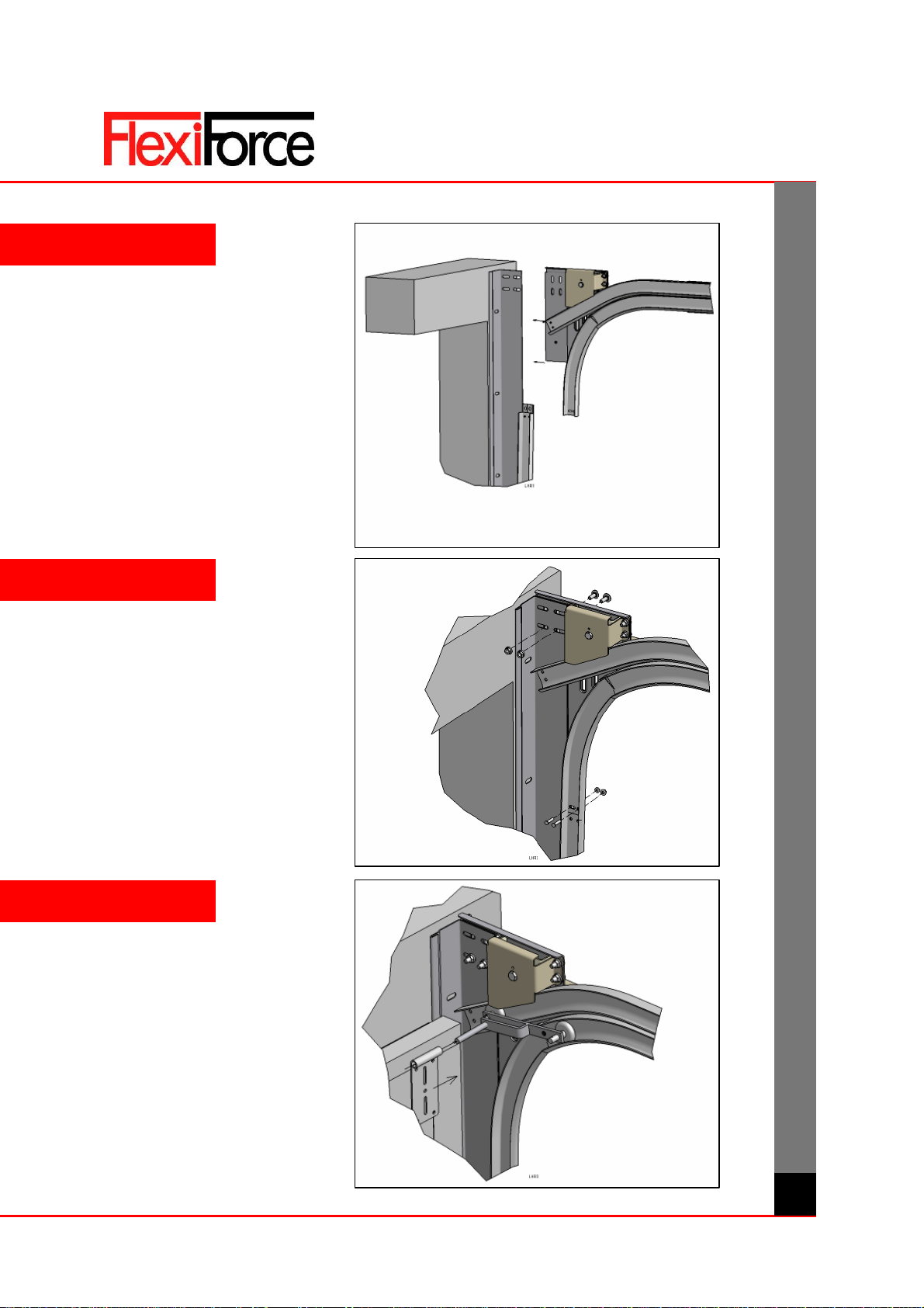
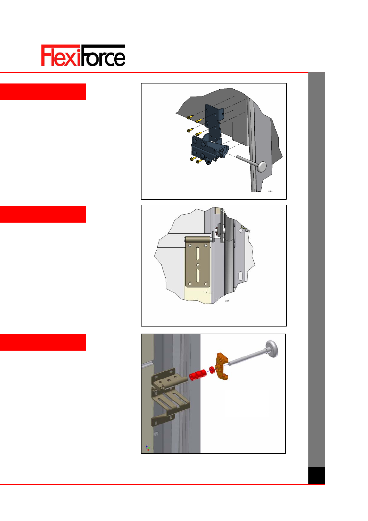
INSTALLATION STEP BY STEP
1
2
3
manual
FF-MANUAL CE-LHR /8 WWW.FLEXIFORCE.COM
GB
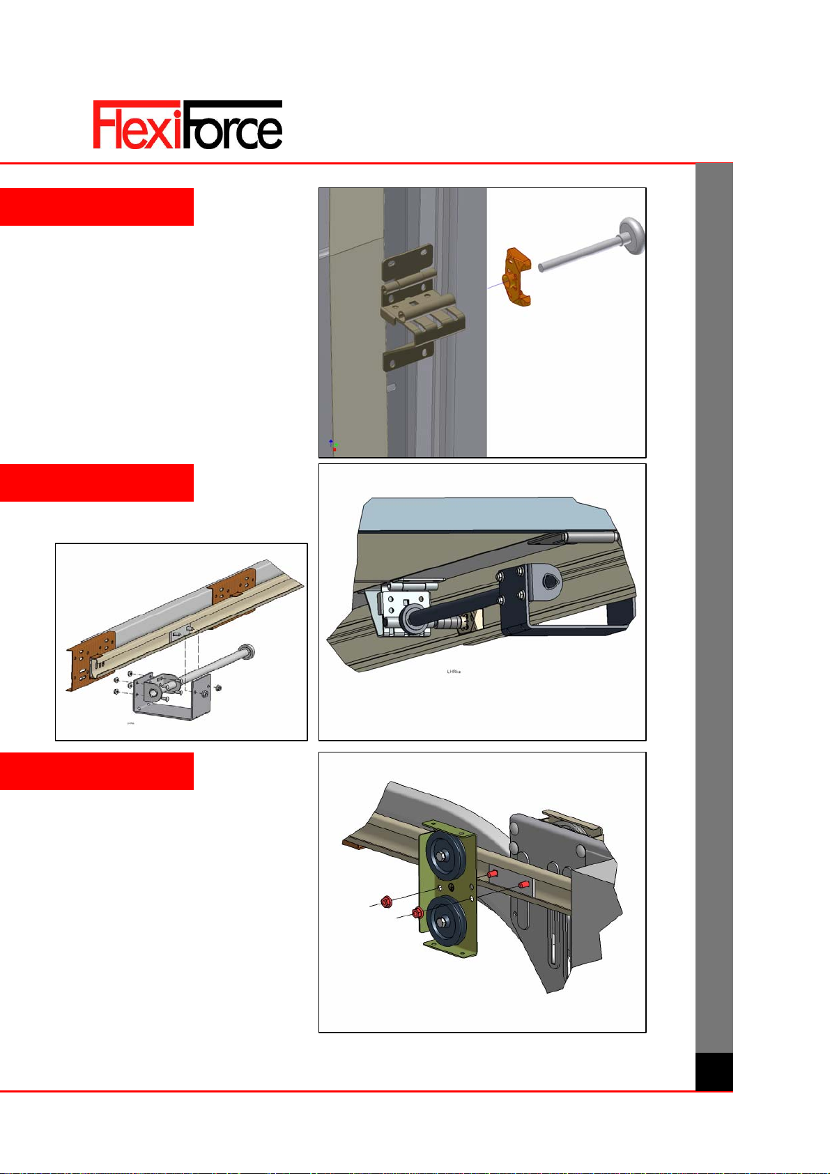
440LHR
575LHR+
580CEN
4
6
5
Roller of upper adjustable hinge must be
filled out with bushes to protect the top
tandem roller.
manual
FF-MANUAL CE-LHR /9 WWW.FLEXIFORCE.COM
GB
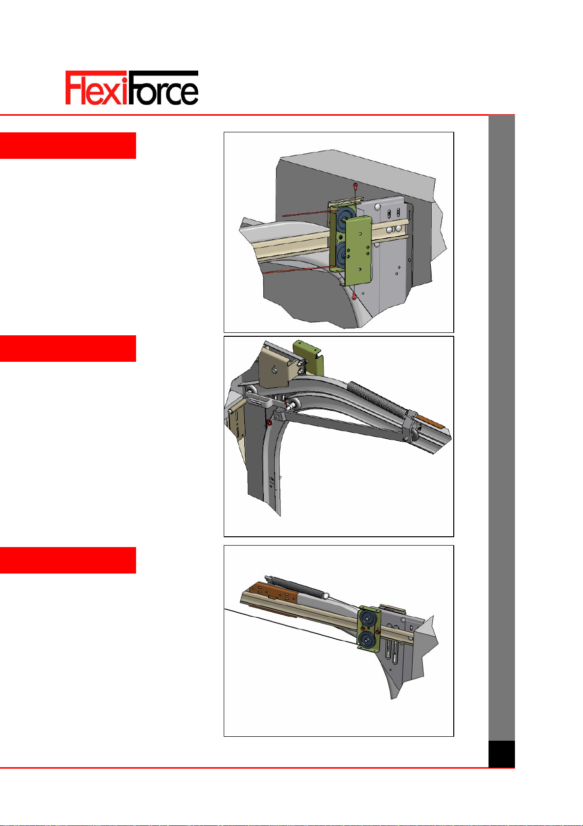
2090L
688CR INSTALLATION
7
8
9
manual
FF-MANUAL CE-LHR /10 WWW.FLEXIFORCE.COM
GB
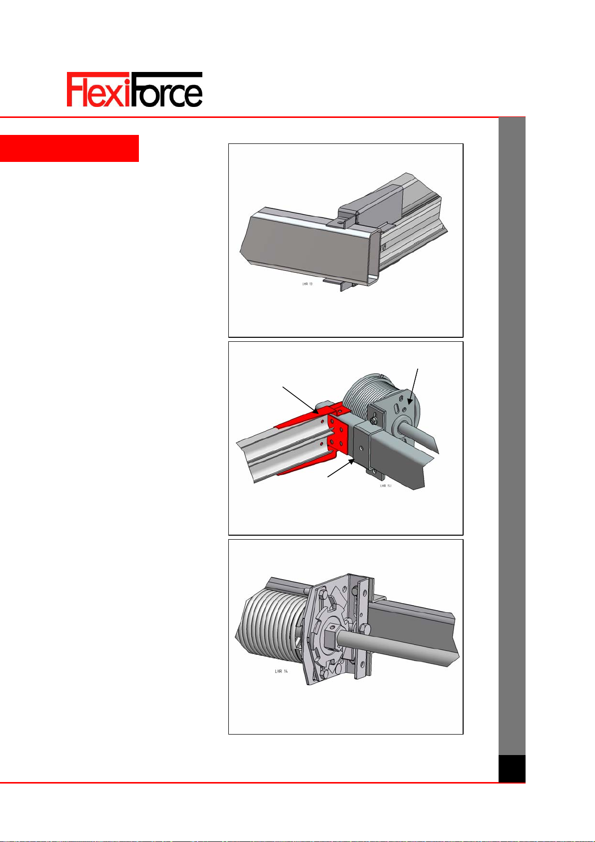
10
11
12
manual
FF-MANUAL CE-LHR /11 WWW.FLEXIFORCE.COM
GB
DETAILS
80K…
35U300LH
35U40
80K…
80K…
3086C…

manual
FF-MANUAL CE-LHR /12 WWW.FLEXIFORCE.COM
GB

manual
FF-MANUAL CE-LHR /13 WWW.FLEXIFORCE.COM
GB

manual
FF-MANUAL CE-LHR /14 WWW.FLEXIFORCE.COM
GB

manual NL
handleiding IND www.flexiforce.com
GEBRUIKERHANDLEIDING
industriële overhead deuren
© All rights reserved. FlexiForce® 2010
manual
NL
manual NL
handleiding IND
2
ATTENTIE! ALGEMENE WAARSCHUWINGEN!
Voor het veilig gebruiken en onderhouden van deze industriële overhead deur
dienen er een aantal voorzorgsmaatregelen te worden genomen. Neem daarom,
voor ieders veiligheid, onderstaande waarschuwingen en aanwijzingen in acht!
Neem bij twijfel contact op met uw leverancier.
! Deze handleiding beslaat het gebruiken en bedienen van de standaard overhead deur. Wellicht dient deze
handleiding te worden aangevuld met separate instructies voor overige componenten.
! Lees deze handleiding vooraf zorgvuldig door.
! Alle geleverde onderdelen zijn berekend voor deze specifieke overheaddeur. Het toevoegen van andere
onderdelen kan nadelige invloed hebben op de veiligheid van de deur. De garantie vervalt indien
onderdelen worden toegevoegd of gewijzigd zonder overleg met de leverancier.
! Laat deze deur niet bedienen door onbevoegden (kinderen!). Zij kunnen gevaar lopen tijdens bediening.
! Aan deze handleiding kunnen geen rechten worden ontleend. Technische wijzigingen zijn voorbehouden
zonder schriftelijke melding.
! Uw leverancier heeft de plicht om uw deur conform de lokaal geldende eisen en normen aan u op te
leveren. Controleert u of de benodigde markeringen (CE) zijn aangebracht en of de benodigde documenten
zijn meegeleverd.
! EEN OVERHEAD DEUR IS EEN ZWAAR EN GROOT BEWEGEND OBJECT. VERKEERDE BEDIENING,
STORING OF ONVOORZICHTIG HANDELEN KAN GEVAAR EN VERWONDINGEN OPLEVEREN!! VOOR
VRAGEN OF ZAKEN DIE NIET, OF ONVOLDOENDE, IN DEZE HANDLEIDING ZIJN TOEGELICHT, DIENT U
CONTACT OP TE NEMEN MET UW LEVERANCIER. GA TEN ALLEN TIJDE VOORZICHTIG OM MET DEZE
OVERHEAD DEUR!!
INDEX
1. Gebruikersdoel pag. 3
2. Functie principe pag. 3
3. Openen en sluiten pag. 3
3.1 Handbediening pag. 3
3.2 Elektrisch aandrijving pag. 3
3.2.1 Bedienen met een bedieningspaneel pag. 3
3.2.2 Bedienen met een handzender pag. 4
3.3 Ketting aandrijving pag. 4
4. Afsluiten pag. 5
5. Loopdeur pag. 5
6. Ongeoorloofd gebruik pag. 5
7. Beveiligingen pag. 5
7.1 Veerbreukbeveiliging pag. 5
7.2 Onderloopbeveiliging pag. 5
7.3 Kabelbreukbeveiliging pag. 5
7.4 Slappe-kabel-beveiliging pag. 5
8. Reparaties, Onderhoud en Storingen pag. 6
9. Leveringscondities en voorwaarden Bijlage
BEKLEMMINGSGEVAAR ! SNIJGEVAAR ! ATTENTIE !
GEVAAR !
manual NL
handleiding IND
3
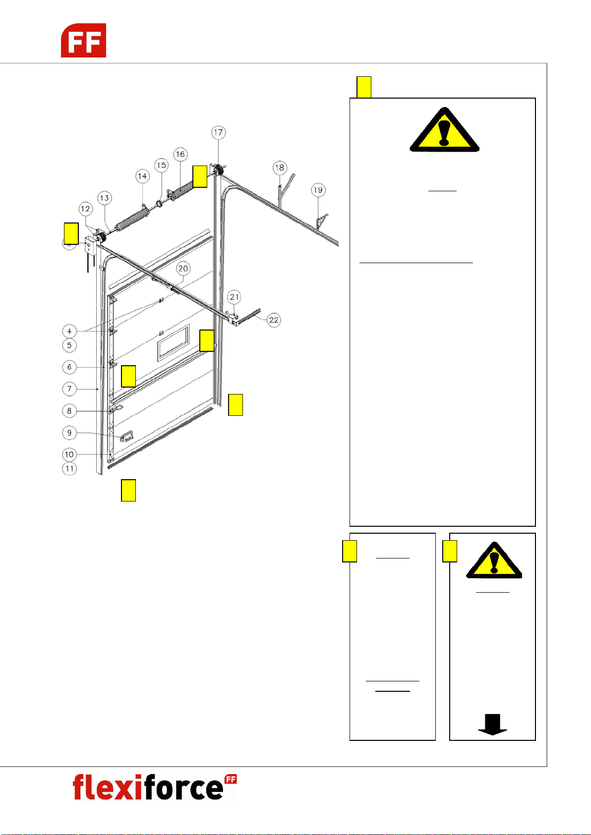
BEGRIPSOMSCHRIJVING + WAARSCHUWINGEN
3 Kettingtakel (bediening)
4 Zij- en middenscharnieren
6 Looprails (geleiding)
7 Hoeklijn
8 Grendel voor afsluiten deur
9 Handgreep/voettrapper
10 Bodemconsole of
kabelbreukbeveiliging
12 Lagerplaten (as systeem)
13 As
14 Balansveren (torsieveren)
15 Koppeling
16 Balansveren (torsieveren)
17 Kabeltrommels met kabel
18 Ophanging aan plafond
19 Ophanging aan plafond
20 Horizontale looprails
21 Veerbumpers
22 Verbinding tussen horizontale rails
A
A
B
B
C
C
LET OP!
VEILIGHEIDINSTRUKTIES VOOR DEZE DEUR
Ondeskundige installatie, onderhoud of verkeerde
bediening van deze deur kan gevaar of
verwondingenveroorzaken.
Deze deur moet voorzien zijn van eenCE-merk!
Volg deze veiligheidsinstructies:
A. Installatie, onderhoud en reparaties mogen
alleen uitgevoerd worden door een
gekwalificeerde en ervaren overhead deur
monteur!
B. Lees voor installatie, onderhoud of reparatie
van deze deur de installatie handleiding. Begin
niet met de werkzaamheden als er geen
handleiding bij de deur aanwezig is!
C. Houd afstand van een bewegende deur. Een
bewegende deur kan gevaar of verwondingen
veroorzaken!
D. Het is verboden om kinderen deze deur te
laten bedienen!
E. Bij het bedienen van de deur met een
afstandsbediening moet u de deur altijd in zicht
houden. Er kunnen mensen (kinderen!) of
spullen in de weg staan.
F. Kijk uit met uw vingers bij bewegende panelen,
rails en andere bewegende onderdelen op
deze deur! Gebruik alleen aanwezige
handgrepen om de deur handmatig te
bedienen!
G. Zorg ervoor dat de deur regelmatig
geïnspecteerd en onderhouden wordt.
C
GEVAAR!
Deze bodemconsole
staat onder hoge
spanning!
NIETZELF
REPAREREN,
DEMONTERENOF
AFSTELLEN!
Dit kan gevaar of
verwondingen
veroorzaken!
Bel een gekwalificeerde
monteur!
A
GEVAAR!
TORSIEVEREN STAAN
ONDER ZEER HOGE
SPANNING!
NIET ZELF
REPAREREN,
AFSTELLEN OF
DEMONTEREN!
Dit kan gevaar of
verwondingen
veroorzaken!
Gekwalificeerde
monteurs:
Lees de handleiding
vóór installatie of
reparatie!
B
manual NL
handleiding IND
4
1. GEBRUIKERSDOEL
De overhead deur is bedoeld om een opening in een
gebouw af te sluiten. Het is niet toegestaan om de
overheaddeur te gebruiken voor andere doeleinden. De
overheaddeur is niet bedoeld als toegangsdeur voor
personen met uitzondering van deuren voorzien van een
loopdeur.
! Lees voordat u werkzaamheden aan de
overheaddeur verricht deze gebruikershandleiding
aandachtig door.
De leverancier is niet verantwoordelijk voor eventuele
schade door foutief gebruik van de overheaddeur.
2. FUNCTIEPRINCIPE
Aan beide zijden van het deurblad bevinden zich de
looprails die voor de geleiding zorgen. Boven het
deurblad bevindt zich de aandrijfas met balansveren,
kabeltrommels en veerbeveiligingen. Het deurblad is aan
stalen kabels opgehangen die bij het openen van de deur
om de kabeltrommels gewikkeld worden. De balansveren
zorgen er voor dat het deurblad in elke positie stilgezet
kan worden met handkracht. De balansveren hebben de
hoogste spanning als de deur gesloten is.
DEMONTEER NOOIT DE KABELS,
KABELTROMMELS OF DE BALANS
VEREN OF ENIG ANDER ONDERDEEL
AAN DE DEUR! ! DIT MAG ALLEEN
DOOR VAKKUNDIG EN GEKWALIFICEERD
PERSONEEL UITGEVOERD WORDEN!
3. OPENEN EN SLUITEN
HOUD TIJDENS HET OPENEN EN SLUITEN
VAN DE DEUR ALTIJD ZICHT OP DE DEUR EN
LET EROP DAT ER ZICH GEEN PERSONEN
OF VOORWERPEN IN DE DEUROPENING OF IN DE
NABIJHEID VAN DE GELEIDING BEVINDEN!
ZET NOOIT IETS ONDER EEN SLECHT
UITGEBALANCEERDE DEUR OM DE
DEUR OPEN TE HOUDEN!
Het openen en sluiten van de deur is afhankelijk van het
bedieningsprincipe waarmee de deur is uitgerust.
Er zijn drieprincipes:
3.1. Handbediening
3.2. Elektrische aandrijving
3.3. Ketting aandrijving
3.1 Openen en sluiten met hand bediening
Bij dit principe wordt de deur met de hand bediend.
OPENEN
De deur bij de handgreep pakken en omhoog trekken.
Het deurblad zoveel snelheid geven dat deze ook met de
hand te stoppen is, dus niet « omhoog gooien ».
SLUITEN
De deur bij de handgreep of bij het touw pakken en naar
beneden trekken.
BEDIEN DE DEUR ALLEEN BIJ DE HANDGREEP OF HET
TOUW! ANDERE ONDERDELEN ZIJN NIET
GESCHIKT OM DE DEUR MEE TE BEDIENEN!
3.2. Openen en sluiten met elektrische aandrijving
Bij dit principe wordt de as van de deur (en daarmee de
deur zelf) met een elektromotor aangedreven. Hierdoor
worden de hefkabels op dan wel afgerold, waardoor het
deurblad omhoog of naar beneden verplaatst wordt.
Hier volgt een verkorte gebruiksaanwijzing, zie voor
uitgebreidere instructie de gebruiksaanwijzing van de
elektrische aandrijving.
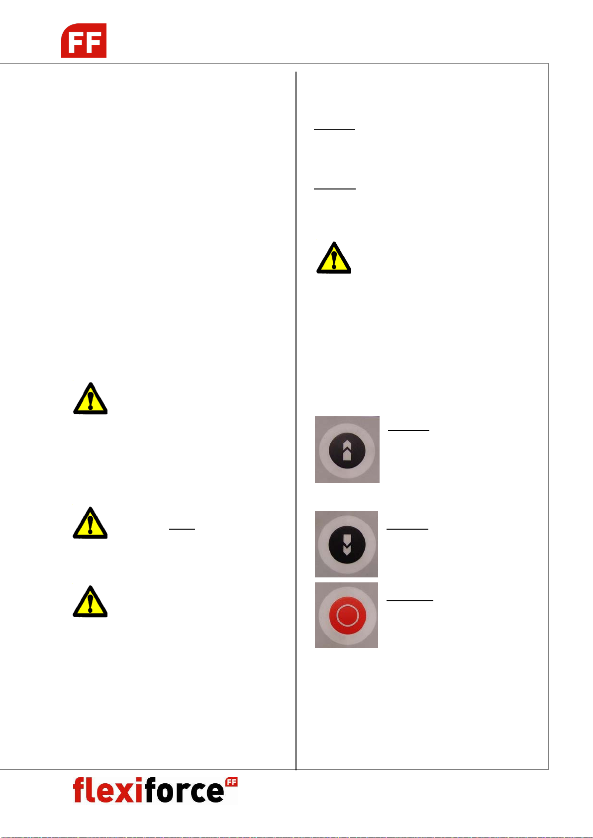
3.2.1 Bedieningmet eenbedieningspaneel
OPENEN
Door op deze knop van het
bedieningspaneel te drukken zal de
deur zich openen (naar boven
bewegen).
SLUITEN
Door op deze knop van het
bedieningspaneel te drukken zal de
deur zich sluiten (naar beneden
bewegen).
STOPPEN
Door op deze knop van het
bedieningspaneel te drukken zal de
deur stoppen.
Door weer op een van de vorige knoppen drukken zal de
deur in de overeenkomstige richting bewegen.

manual NL
handleiding IND
5
Ontkoppelen met noodhandketting:
De handketting van de elektromotor dient alleen bij
stroomuitval of bij een defect aan de aandrijving voor het
handmatig openen en sluiten van de deur. Met de
hoofdschakelaar eerst de netspanning uitschakelen.
Rechts aan de ketting trekken : Deur dicht.
Links aan de ketting trekken : Deur open.
De noodhandketting komt na gebruik automatisch terug
naar de neutrale positie.
Na stroomstoringen of her-inschakelen van de
aandrijvingsbesturing dient de deur één keer compleet te
worden geopend.
3.2.2Bedieningmeteen handzender
DE DEUR KAN MET DE HANDZENDER
NIET TIJDENS OPENEN OF SLUITEN
WORDEN GESTOPT MAAR ZAL DE
INGEZETTE BEWEGING GEHEEL
AFMAKEN. BEDIEN NOOIT DE DEUR MET EEN
HANDZENDER ALS U DE DEUR NIET IN HET ZICHT
HEEFT! ER KUNNEN ZICH OBSTAKELS OF
PERSONEN IN DE OPENING BEVINDEN!
OPENEN
Door op een van de geprogrammeerde knop van de
handzender te drukken zal de deur zich openen.
SLUITEN
Door op een van de geprogrammeerde knop van de
handzender te drukken zal de deur zich sluiten
3.3Openen ensluitenmet eenketting aandrijving
Bij dit principe wordt de as van de deur met een
kettingtakel aangedreven. Hierdoor worden de hefkabels
op dan wel afgerold, waardoor het deurblad omhoog of
naar beneden verplaatst wordt en de deur zich dus opent
of sluit.
OPENEN
Pak met beide handen één zijde van de ketting vast en
trek deze rustig naar beneden en de deur zal openen.
Tijdens de beweging afwisselend met de linker en
rechterhand trekken.
HOUD DE KETTING ALTIJD MET
MINSTENS EEN HAND VAST OM DE
BEWEGING GOED TE KUNNEN CON-
TROLEREN. NA BEDIENEN DE KETTING
ALTIJD IN DE KETTINGSTOP VERGRENDELEN.
SLUITEN
Met beide handen een zijde van de ketting vastpakken
en rustig naar beneden trekken en de deur zal sluiten
Tijdens de beweging afwisselend met de linker en
rechterhand trekken.
HOUD DE KETTING ALTIJD MET
MINSTENS EEN HAND VAST OM DE
BEWEGING GOED TE KUNNEN CON-
TROLEREN. NA BEDIENEN DE KETTING
ALTIJD IN DE KETTINGSTOP VERGRENDELEN.
DE KETTINGSTOP IS ONGESCHIKT OM EEN
UIT BALANS ZIJNDE DEUR VAST TE ZETTEN.
IS DE DEUR UIT BALANS DAN MOET EEN
VAKKUNDIG MONTEUR DE ONBALANS
CORRIGEREN VOORDAT DE DEUR VERDER BEDIEND
MAG WORDEN!
EEN DEUR MET EEN KETTING
AANDRIJVING M AG NIET OP EEN
ANDERE MANIER BEDIEND WORDEN,
OMDAT DE MEE LOPENDE KETTING
GEVAAR KAN VEROORZAKEN!
4. AFSLUITEN
Bij het afsluiten van een overhead deur met een slot of
grendel moeten de volgende zaken in acht worden
genomen.
Een slot in combinatie met elektrische bediening moet
voorzien zijn van een schakelaar, die verhindert, dat de
aandrijving in werking kan treden als de deur vergrendeld
is. Dit voorkomt dat de aandrijving of de deur beschadigd
wordt en gevaar kan veroorzaken.
Om de handbediende of kettingbediende deur
gemakkelijker te sluiten kan, door de voet in de
handgreep te zetten, de deur naar beneden gedrukt
worden.
4.1 Grendel
Met een grendel kan de deur van binnenuit
afgesloten worden.
4.2 Buitenslot
Met een buitenslot kan de deur zowel van binnen als van
buiten vergrendeld worden.
This manual suits for next models
1
Table of contents
Languages:
Other FlexiForce Door Opening System manuals


Popular Door Opening System manuals by other brands

Dorma
Dorma ES 410 Mounting instruction and Operation manual

Colcom
Colcom Biloba Unica 100E10 Instruction of Assembly

Tormax
Tormax iMotion 1401 manual

Next Systems
Next Systems 900 INSTRUCTIONS MANUAL FOR THE USE & MAINTENANCE

Nabco
Nabco GYRO TECH GT-1175 Wiring and Programming Manual

Tucker Auto-Mation
Tucker Auto-Mation SW10 installation guide


