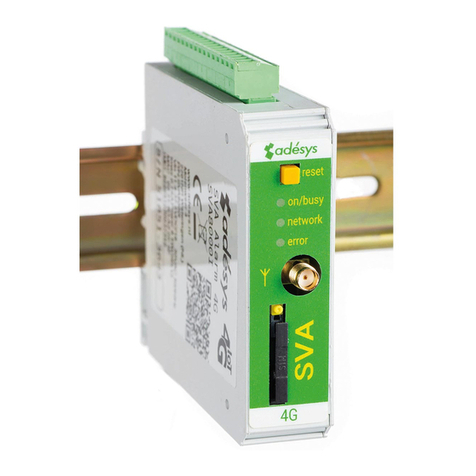
Flexitron webdyn MTX-StarSensor User manual

MTX-StarSensor
Manual local conguration
www.webdyn.com

contact@webdyn.com | webdyn.com
V1.0 subject to change | Webdyn © by Flexitron Group
2
Index
MTX-StarSensor local conguration................................................................................................................3
1. Introduction................................................................................................................................................................................................................3
2. MTX-StarSensor operating modes.....................................................................................................................................................4
2.1 Placing the MTX-StarSensor in conguration mode. ............................................................. 4
2.2 Connections required to congure the MTX-StarSensor correctly........................................ 4
3. Conguration software..................................................................................................................................................................................5
3.1 Sections of the conguration software................................................................................... 8
3.1.1 GENERAL CONFIGURATION section........................................................................... 8
3.1.2 READ DATA / TOOLS Section...................................................................................... 22
1. APPENDIX: Example of commissioning a VEGAPULS C11 sensor..........................................................................30
2. APPENDIX: Example of initializing a Hydrostatic Pressure Sensor....................................................................39
Contact ..........................................................................................................................................................................................49

contact@webdyn.com | webdyn.com
V1.0 subject to change | Webdyn © by Flexitron Group
3
MTX-StarSensor local conguration
1. Introduction
The MTX-StarSensor is a ULP (Ultra Low Power) device that periodically reads data from 4-20mA type
sensors. It has an internal battery pack that powers the MTX-StarSensor device itself, as well as the
4-20mA sensor. The readings are stored in its internal non-volatile memory and can be automatically
sent to a remote server/platform via FTP, MQTT (optional) via a 2G, 3G or 4G network (depending on the
version). If the MTX-StarSensor device is installed in a location with no coverage, the stored data can be
downloaded locally via an RS232 serial bus connected to a Windows 10 PC or Tablet, or via Bluetooth.

contact@webdyn.com | webdyn.com
V1.0 subject to change | Webdyn © by Flexitron Group
4
2. MTX-StarSensor operating modes
The MTX-StarSensor device has two modes of operation. The rst is normal mode, in which the MTX-
StarSensor device performs the tasks for which it has been congured (waking up at certain times,
taking 4-20mA sensor readings, sending data through the cellular network if it is congured to do this,
etc.). The second is the conguration mode. In conguration mode, the MTX-StarSensor device can be
congured locally using an RS232 serial cable or via Bluetooth communication and can also be used to
read the 4-20mA sensor data records stored in the internal memory, in the event that they are not being
transmitted over the cellular network.
2.1 Placing the MTX-StarSensor in conguration mode.
Before entering conguration mode, the SIM card must be inserted correctly into the MTX-StarSensor
and the antenna must be connected.
To put the MTX-StarSensor device in conguration mode, simply bring a magnet close to the indicated
point on the MTX-StarSensor.
The LED on the MTX-StarSensor will then illuminate. This indicates that the MTX-StarSensor has detected
the magnet, it will then wake up and enter conguration mode. After about 15 seconds the LED will ash
intermittently. This indicates that the MTX-StarSensor device is in conguration mode and is ready to be
congured via the RS232 serial port or a Bluetooth wireless connection.
2.2 Connections required to congure the MTX-StarSensor correctly
Communication via the RS232 serial cable.
To communicate locally with the MTX-StarSensor, a Windows 10 computer or tablet and an RS232 serial
port are required. If the computer or tablet does not have an RS232 serial port, a USB/RS232 converter
can be used.
Communication via Bluetooth:
To communicate locally with the MTX-StarSensor, a Windows 10 computer or tablet with a compatible
Intel Bluetooth module is required.

contact@webdyn.com | webdyn.com
V1.0 subject to change | Webdyn © by Flexitron Group
5
3. Conguration software
The MTX-StarSensor conguration software has the following appearance.
First decide whether you are going to access the MTX-StarSensor via an RS232 serial cable connection
or wirelessly via Bluetooth, and proceed as follows:
Conguration using the RS232 serial cable:
At the top of the screen, select the “SERIAL PORT” option and the RS232 serial port number to be used,
this is the COM number of the PC or Tablet that will be used to communicate with the MTX-StarSensor
device.

contact@webdyn.com | webdyn.com
V1.0 subject to change | Webdyn © by Flexitron Group
6
Once this is done, click on the “Login” button located at the bottom of the screen, after which another
screen will appear, as follows.
Here you can enter the password to access the MTX-StarSensor device. The default (factory) password is
“mtx”, in lower case. This can be changed later in the conguration program.
Once this is done, and if the password is correct, the current conguration of the device will be loaded
automatically, as shown on the screen.
Communication via BLUETOOTH:
The “BLUETOOTH” option should be selected at the top of the screen.
Once the BLUETOOTH option has been selected, click on the “Login” button located at the bottom of
the screen, after which another screen will appear as follows. This shows the MTX-StarSensor devices
that have been accessed within the last hour. The “Search” button must be clicked to scan for MTX-
StarSensor devices. Before clicking on the “Search” button, make sure that you have Bluetooth activated
on your Windows 10 PC or tablet.

contact@webdyn.com | webdyn.com
V1.0 subject to change | Webdyn © by Flexitron Group
7
After the search, the discovered devices will appear. Select the device you want to access and click on
the “Select” button.
Once connected via Bluetooth, a screen will appear as follows.
On this screen you must enter the password to access the device. The default (factory) password is “mtx”,
in lower case. You can change it later using the conguration software.
Once this is done, and if the password is correct, the current conguration of the device will be loaded
automatically, as shown on the screen.

contact@webdyn.com | webdyn.com
V1.0 subject to change | Webdyn © by Flexitron Group
8
3.1 Sections of the conguration software
The conguration software has two well-differentiated sections which can be accessed from the upper
tabs. The “GENERAL CONFIGURATION” menu, containing the various conguration options for the MTX-
StarSensor device, and the “READ DATA / TOOLS” menu, from where it is possible to perform sensor
measurement tests, 2G/3G/4G transmission tests, set local time, download stored data, etc. It also
includes the “IMPORT/EXPORT CONFIG” menu. This option lets you export the conguration shown on
the screen to a le and import other congurations from les.
NB: if you import a conguration from one MTX-StarSensor to another, do not forget to congure the
device ID eld afterwards. Furthermore, once an imported conguration has been applied to an MTX-
StarSensor, it must still be calibrated.
3.1.1 GENERAL CONFIGURATION section
The general conguration section is divided into several other sections. Here we will describe each one.
3.1.1.1 SIM card conguration
In this section you must enter the APN, USER and PASSWORD parameters for the SIM card provided
by your operator, i.e. the parameters that enable the modem to access the 2G, 3G or 4G networks
(depending on the module) for the automatic sending of data and remote conguration.

contact@webdyn.com | webdyn.com
V1.0 subject to change | Webdyn © by Flexitron Group
9
The radio technology to be used can be congured (AUTO, 2G, 3G or 4G (depending on the model)). We
recommend you use AUTO, the modem will then automatically choose the best available technology. It
may be useful to specify a specic technology (to shave a few seconds off the network connection time)
in locations where you clearly only have one technology available (e.g. 2G only), or if your SIM card only
works with a certain technology.

contact@webdyn.com | webdyn.com
V1.0 subject to change | Webdyn © by Flexitron Group
10
3.1.1.2 FTP server conguration
One method of sending recorded data is by FTP. From the conguration box selected below you can enter
the various parameters for FTP communication.
Description of each of the FTP service conguration parameters:
• Server: an IP or DNS which can be indicated with: the TCP port to be used. Example: x.x.x.x:21
• User: the FTP server user
• Password: the FTP server password
• Path: full directory path where the output les will be sent.
• Mode: you can choose “Passive” or “Active”, depending on the type of SIM card (private or
public IP) and the security settings of your server.
• Transfer Type: ASCII or BINARY. Select ASCII, the data collected by the MTX-StarSensor is
always of the ASCII type.

contact@webdyn.com | webdyn.com
V1.0 subject to change | Webdyn © by Flexitron Group
11
3.1.1.3 MQTT server conguration
(The MQTT option is only available on request) This section must be congured if you are going to
use an MQTT platform to receive the data stored in the sensor, or if you intend to implement a device
management platform. If you only need to send sensor data via FTP, do not enable this section, you will
save power and therefore battery life.
Description of each of the MQTT service conguration parameters:
• Enabled: checkbox to enable MQTT communications
• Server: MQTT server URL in the format tcp://xxx.xxx.xxx.xxx:1883 or ssl://xxx.xxx.xxx.xxx:8883
where xxx.xxx.xxx.xxx can be an IP or DNS address
• ID: identier of the device on the MQTT platform
• User: Username of the device on the MQTT platform
• Password: password of the device on the MQTT platform
• LOG topic: MQTT topic to which the stored sensor data will be sent

contact@webdyn.com | webdyn.com
V1.0 subject to change | Webdyn © by Flexitron Group
12
NB: The information sent by the LOGGER frame, in JSON format, will be similar to the following:
{“MTX-00067”:[{“data”:{“S”:0,”D”:30.94,”C”:6.958,”A”:0,”P”:10.8,”R”:19,”T”:”3g”,”N”:903},”t
ime”:”2021-10-13T08:15:17Z”}]}
Where:
“S”: indicates the type of 4-20mA sensor (0=pressure, 1=radar, 2=generic)
“D”: Indicates the measurement. In the case of a pressure sensor, it indicates the distance in
metres between the well-head and the surface of the water, for a radar sensor, it indicates the
water level of the well, and for a generic sensor, it indicates the current in the sensor.
“C”: Sensor current in mA
“A”: Indicates if there is an alarm. 0=No alarm, 1=Low value alarm, 2=High value alarm.
“P”: Battery voltage
“R”: coverage level (0…31)
“T”: technology: 2g, 3g, 4g
“N”: Number of transmissions made up to the time of the sensor reading.
“time”: current time of the MTX unit in UTC format
• DNS Topic: MQTT topic to which the MTX-StarSensor status data will be sent each time the
device has IP communication
NB: The information sent by the DNS frame, in JSON format, will be similar to the following:
{“data”:{“IMEI”:”357150691743852”,”TYPE”:”DNS”,”ID”:”MTX-00067”,”IP”:”176.82
.197.183”,”CSQ”:12,”TECH”:”3g”,”VER”:”11.08.33.23”,”MOD”:”199810082”,”CID”-
:”214;07;0363;9CC20E5”,”VPOW”:10767},”time”:”2021-10-13T08:05:58Z”}
Where:
“IMEI”: is the modem’s IMEI
“TYPE”: is the type of MQTT frame sent
“ID”: is the unique identier of the MTX unit
“IP”: is the current IP address of the MTX unit
“CSQ”: is the RSSI strength (0...31)
“TECH”: is the technology used
“VER”: is the rmware version of the MTX unit
“MOD”: is the MTX model code
“CID”: GSM cell identication
“VPOW”: battery voltage
“time”: UTC time of the MTX unit

contact@webdyn.com | webdyn.com
V1.0 subject to change | Webdyn © by Flexitron Group
13
• AT topic: MQTT topic for sending AT commands to the MTX-StarSensor remotely (read status,
read and change conguration, etc.).
NB: If MQTT communication is enabled, it is highly recommended that the MQTT broker sends
an AT^MTXTUNNEL=NOREQUEST command to the MTX modem after the broker has received
the DNS frame (i.e. the status information frame of the MTX), if no other AT commands need to
be sent to the modem (i.e. to perform a remote FW update). Sending this command will prevent
the MTX modem from staying connected to the broker via MQTT for longer than is necessary
(waiting to receive other AT commands), so saving energy. This will improve battery life.
• ATR Topic: MQTT topic to which the MTX-StarSensor will send responses to the AT commands
received in the “AT Topic”.
3.1.1.4 Conguring NTP time servers
The MTX-StarSensor has an internal clock. This clock can be synchronized in two ways. Locally and
manually (for locations without 2G / 3G /4G coverage (or for initialization of the MTX-StarSensor device)
and automatically using NTP time servers.

contact@webdyn.com | webdyn.com
V1.0 subject to change | Webdyn © by Flexitron Group
14
Two NTP time servers must be entered here for automatic date/time synchronization. Automatic
synchronization via NTP will only occur when the MTX-StarSensor device connects to the IP network to
send data automatically. It uses this opportunity to connect to the network, therefore saving energy and
increasing battery life.
3.1.1.5 Sensor conguration
This section covers conguration and initialization of the sensor.
Descriptions of the Sensor 4-20mA conguration parameters:
• ID: sensor identier eld. It must be unique in the sensor network. This eld will be used to
create the names of the data les sent via FTP, meaning each device on the network must have
a different identier. The identier will always have the structure MTX-XXXXX where XXXXX are
alphanumeric characters
• Sensor Type: the MTX-StarSensor currently supports three types of 4-20mA device: “Submersible
Pressure Sensor”, “VEGAPULS C11 Radar” and “Generic 4-20mA”

contact@webdyn.com | webdyn.com
V1.0 subject to change | Webdyn © by Flexitron Group
15
• Voltage: lets you specify the supply voltage of the 4-20 mA sensor. Depending on the MTX-
StarSensor model, it can be set at 24V or between 12V and 32V.
• Time: species the number of seconds during which the Voltage is applied to the Sensor before
the measurement is taken, to stabilise it beforehand. For VEGAPULS C11 sensors, select 10
seconds.
• The following conguration parameters do not apply to the generic 4-20mA sensor.
• Range: maximum measurement range of the sensor in use (indicated on the sensor’s
datasheet). For the VEGAPULS C11 sensor, this is 8 (metres).
• Offset: minimum measurement value in mA, usually 4. For the VEGAPULS C11 sensor, enter 4.
• Span: the sensor’s measurement range in mA (indicated on the sensor’s datasheet). This is
the maximum amplitude of the sensor in mA from the offset, typically 16. For the VEGAPULS
C11 sensor, enter 16.
• Initial Col: for the “Radar VEGAPULS C11” sensor this indicates the initial water level, from the
bottom to the surface. For a “Submersible water pressure” type sensor, this indicates the initial
water column from the surface to the sensor.
• Initial Dist: for the “Radar VEGAPULS C11” sensor type, this indicates the initial distance
from the sensor (Radar) to the object to be measured (e.g. water surface). The “Initial Dist”
parameter changes to “Initial Value” when selecting the “Generic 4-20mA” sensor type. For the
“Submersible water pressure” type sensor, it indicates the initial distance between the well-
head and the surface of the water.
• “Initialize Sensor” button
This button starts the sensor initialization procedure.
For the “Radar VEGAPULS C11” type sensor, a screen similar to the one shown below will
appear when it is clicked.
This screen is used to initialize the MTX-StarSensor to read the 4-20mA sensor. Enter the Range, Offset
and Span values for the 4-20mA sensor you want to use. For the VEGAPULS C11 sensor, enter the value

contact@webdyn.com | webdyn.com
V1.0 subject to change | Webdyn © by Flexitron Group
16
8 (default value for the VEGA PULSC11 sensor, or the maximum range value congured in the VEGAPULS
C11 sensor if it has been changed, with a minimum of 1m. Remember that the minimum range value
of the VEGAPULSC11 sensor must always be 0m). The Offset and Span values must be set at 4 and 16
respectively.
Then enter the Level and Distance data.
“Level” indicates the initial water level from the bottom to the surface (in metres). Use a millimetric tape
measure, or millimetric metal rod to obtain the initial reference reading. Try to make the measurement
as accurate as possible.
"Distance". Optional. This indicates the distance (in metres) from the water surface to the VEGAPULSC11
sensor. Leave the “Distance” box blank if you want to initialize the MTX-StarSensor with the measurement
obtained directly from the VEGAPULSC11 sensor. Alternatively, if you want to improve the accuracy of the
MTX-StarSensor’s measurements, enter the initial distance (in metres to 3 decimal places X.XXX) from
the water surface to the VEGAPULSC11 sensor in the “Distance” box.
“Power Sensor” - If you need to congure the VEGAPULS C11 sensor, for example to set the maximum
reading range, you can click the button to power it on. You can then use the VegaTool app to do this.
To nish the initialization process, once you have obtained the distance between the VEGAPULS C11
sensor and the water surface, enter it in the conguration screen (“Distance” box) and click “OK” to start
the MTX-StarSensor’s initialization calibration process. Below is an example screen, where the "Level"
(the measurement between the bottom and the water surface is 1.2 meters) and the "Distance" (the
measurement between the water surface and the VEGAPULSC11 sensor) is 0.717 metres.
NB: If you have changed the sensor Range using the Vega Tools app (e.g. a Range of 4m instead of 8m)
you will need to adjust it on the previous screen before pressing “OK”. The minimum range of the sensor
must be set to 0m (the factory setting).
For the “Submersible Water Pressure” type sensor, pressing the “Initialize Sensor” button will display the
screen shown below.

contact@webdyn.com | webdyn.com
V1.0 subject to change | Webdyn © by Flexitron Group
17
This screen is used to calibrate the MTX-StarSensor for the 4-20mA sensor reading. Enter the Range,
Offset and Span values for the 4-20mA sensor you want to use. For the 4-20 “Submersible water pressure”
sensor, enter the Range (the maximum distance in metres that the sensor is capable of reading), the
Offset (in mA, normally 4) and the Span (in mA, normally 16).
You must then enter the Distance.
"Distance" indicates the distance between the well-head to the surface of the water. Use a millimetric tape
measure, or millimetric metal rod to obtain the initial reference reading. Try to make the measurement
as accurate as possible.

contact@webdyn.com | webdyn.com
V1.0 subject to change | Webdyn © by Flexitron Group
18
3.1.1.6 Read and send settings
In this section we will congure all parameters related to the mode and period for reading and sending
data.
• Send Mode: mode for sending the collected data to the server. You can choose between FTP
and MQTT (optional). Choose NONE if you do not want to send data by IP (e.g. if you only want
to use a SERIAL cable or BLUETOOTH)
• Max time: indicates the time, in seconds, that the MTX-StarSensor device can be connected
to the 2G, 3G or 4G network (depending on the model). If the MTX-StarSensor device has not
been able to make a connection within that time, or has not been able to send the data, it will
end the sending process in order to save battery life.
If the data are sent within the maximum time window, the connection will be closed immediately
in order to save power. The MTX-StarSensor will also attempt to synchronize its time setting with
the congured NTP time servers during this window. Make sure the time servers are correctly
congured, as the connection time could be increased by between 7 and 14 seconds.

contact@webdyn.com | webdyn.com
V1.0 subject to change | Webdyn © by Flexitron Group
19
• Time base: indicates the time base for reading and sending data. Two values are possible:
hours and minutes. Use of the “hours” time base is STRONGLY recommended. Using the
“minutes” time base will drastically reduce battery life.
• Readings: indicates the hours or minutes (depending on the congured time base) at which the
MTX-StarSensor will wake up to read the 4-20mA sensor
• Sends: indicates the hours or minutes (depending on the congured time base) at which
the MTX-StarSensor will send the data stored in its non-volatile memory to the FTP or MQTT
platform. Please note that it is only possible to select send hours or minutes that coincide with
sensor reading hours or minutes, in order to save energy and prolong battery life.
• Alarm mode: one of these modes can be selected: “off”, “on” and “smart”.
The “off” option species that no alarms are set on the MTX-StarSensor.
The “on” option species that alarms are congured on the MTX-StarSensor. This implies that,
if the recorded level is lower or higher than certain thresholds, the alarm will be triggered. In
the "on" operating mode, if an alarm is triggered, a data send will also be activated (via FTP or
MQTT depending on the congured sending mode) regardless of whether data is congured to
be sent at that time. The “on” mode can signicantly increase energy consumption, as, if the
level measured by the MTX-StarSensor is within the alarm ranges every time a reading is taken,
the data will always be sent. This will signicantly reduce battery life. For example, if you have
congured the MTX-StarSensor to take 1 reading every hour and to perform 2 sends per day,
but the alarm state is active throughout the day, 24 data sends will be made instead of the 2
congured, which will signicantly reduce battery life.
The “smart” option is similar to the “on” alarm option, but it works in an intelligent manner.
When an alarm is triggered, the option to send data to the server is also triggered in order to
report the situation, but automatic sending will not occur again until the alarm is reset, i.e. until
the alarm is deactivated again, so preventing the MTX-StarSensor from automatically sending
data whenever it is in an alarm condition, so prolonging the life of the batteries.
• Thresholds: for the VEGAPULSC11 sensor, this species the minimum and maximum thresholds
(in metres) for the water level that must be read by the MTX-StarSensor to trigger an alarm.
A hysteresis value (in metres) can also be entered to prevent continuous alarm triggers on
reaching the exact level.
For generic 4-20 milliamp sensors, the threshold data (minimum, maximum and hysteresis)
are indicated in metres.
Below is an example showing the difference between the “on” and “smart” alarm modes.
EXAMPLE
For a VEGAPULSC11 sensor, the alarm mode is congured for a minimum threshold of 2m and
a maximum of 4m, with a hysteresis of 0.1m. It is also congured to read the sensor every hour
(24 readings per day) and to perform only 2 sends per day (at 00:00 and 12:00), via FTP.

contact@webdyn.com | webdyn.com
V1.0 subject to change | Webdyn © by Flexitron Group
20
If the alarm mode is set to “on”, as soon as the sensor measures a level lower than 2m or
higher than 4m, the alarm will be triggered. For example, let's imagine the time is 03:00, the
MTX-StarSensor wakes up and reads a distance of 1m. At that moment, as the distance value
is less than 2m, the alarm will be triggered, as will the sending process, even if the data are
not scheduled to be sent at 03:00. An hour later, the MTX-Starsensor wakes up again at 04:00
to take the next sensor reading, it reads 1m again. As it is still in alarm condition, the data are
sent again at 04:00. At 05:00 it wakes up and takes a reading again, it reads 1.1m, so a send
is performed once again. And so on until the alarm condition is not met, which, in this case, will
be at 2.1m (2 metres + the hysteresis value of 0.1m). This can greatly reduce battery life due
to the large number of sends performed. Next we will look at “smart” mode.
If the "smart" alarm mode is congured, as soon as the distance measured by the sensor is less
than 2m or greater than 4m, the alarm will be triggered. For example, let's imagine the time is
03:00, the MTX-StarSensor wakes up and reads a distance of 1m. At that moment, since the
value of the distance is less than 2m, the alarm will be triggered, and also the sending process,
even if the data are not programmed to be sent at 03:00. An hour later, the MTX-Starsensor
wakes up again at 04:00 to take the next sensor reading, it reads 1m again. Here, if the alarm
that occurred at 03:00 was sent successfully, the data are NOT resent at 04:00. At 05:00 it
wakes up again and takes a reading of 1.1m and, as it is still in alarm condition, but a correct
send occurred at 03:00, a send is NOT performed again. And so on until the alarm condition
is not met, which, in this case, will be at 2.1m (2 metres + the hysteresis value of 0.1m). From
this moment on, if a new alarm condition were to occur, for example at a distance of 1.9m, the
alarm would be activated and the data sent again.
• “Edit Schedules” button. This button can be used to congure the "time base" and the hours
or minutes at which data are to be read and sent. When you click on this button, the following
window will appear:
Other manuals for webdyn MTX-StarSensor
1
Table of contents
Other Flexitron Modem manuals
Flexitron
Flexitron MTX-G-JAVA-T Series Installation manual
Flexitron
Flexitron Webdyn MTX-StarEnergy Driver ETH-USB User manual

Flexitron
Flexitron MTX-4G-JAVA-IoT User manual
Flexitron
Flexitron webdyn MTX-StarSensor Installation manual
Flexitron
Flexitron WebdynEasy LoRaWAN User manual
Flexitron
Flexitron Mtx MTX-STARENERGY-M User manual

