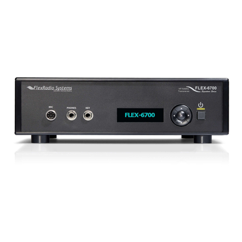
FlexRadio Systems FLEX-5000 Series User manual

The
Series
®®
Owner's Manual
Version 1.14.0
HF-6m Transceivers

SOFTWARE DEFINED RADIO
The FLE -5000 Series Owner's Manual
2003−2008 FlexRadio Systems®
All Rights Reserved
Reproduction of this document in any form is expressly forbidden unless explicitly
authorized by FlexRadio Systems.
Information contained in this document may contain technical inaccuracies or typographical
errors. Information may be changed or updated without notice. FlexRadio Systems may
ma e improvements and/or changes in the materials at any time without notice.
All materials are provided "as is". FlexRadio Systems ma es no representations or
warranties, expressed or implied to the accuracy of the copyrighted materials. FlexRadio
Systems will not be liable for any direct, indirect, special or consequential damages arising
out of any use of the document.
FlexRadio Systems is a registered trademar of Bronze Bear Communications, Inc. DBA
FlexRadio Systems.
The FlexRadio Systems Waves Design (logo), SDR-1000, FLEX-5000 and the FLEX-5000
logo, FlexWire, Clic Tune, MultiRX, PanaFall and PanaScope are trademar s of FlexRadio
Systems.
FlexRadio Systems
13091 Pond Springs Rd #250• Austin, TX 78729
Phone: (512) 535-4713• Fax: (512) 233-5143
Email: sales@flex-radio.com
Editor: Joe de Groot – AB1DO
Printer/Distributor: Peter Markavage - WA2 WA
i 2003-2008 FlexRadio Systems

Table of Contents
PREFACE.....................................................................................XI
ACKNOW EDGMENTS..............................................................XIII
USING THIS MANUA IN ITS PDF FORM...................................XV
1 HARDWARE INSTA ATION.......................................................1
UNPA KING AND DE IDING ON A LO ATION..............................................................2
Contents of the Carton...................................................................................................2
Location Considerations.................................................................................................3
PHYSI AL ONNE TIONS.............................................................................................3
Front Panel...................................................................................................................4
(1) LED Push Button Power Switch.............................................................................................4
(2) Headphone Jack................................................................................................................5
( ) Microphone Connector........................................................................................................5
(4) Internal Speaker (FLEX-5000C Only)....................................................................................6
Bac Panel...................................................................................................................6
(1) Primary Antenna Ports (ANT1, ANT2 & ANT )........................................................................7
(2)-( ) Receive Only Antenna Ports (RX1 IN & RX2 IN).................................................................7
(2) External RX1 OUT to RX1 IN Receive Loop.............................................................................7
(4)-(5) Dedicated Transverter Connections.................................................................................7
(6) 1 .8 VDC Power Socket......................................................................................................7
(7) Dual IEEE 1 94 FireWire® Jacks..........................................................................................8
(8) Straight Key or Paddles (KEY)..............................................................................................8
(9) External Keying Lines (AMP RLY TX1, TX2 & TX )...................................................................9
(10) External Frequency Reference Input....................................................................................9
(11) Powered Speaker/Line Out Jack........................................................................................10
(12) FlexWire™ Peripheral Interface Bus...................................................................................10
(1 ) Line-Out and Line-In Audio Jacks......................................................................................11
(14) Balanced Line Input........................................................................................................11
Connecting to a Balanced XLR Connector...................................................................................................11
(15) PTT Jack.......................................................................................................................12
(16) RF Ground Terminal........................................................................................................12
FLEX-5000C Computer Connections...............................................................................13
Wireless Keyboard and Mouse.................................................................................................1
FireWire Cable......................................................................................................................1
Monitor or LCD Display...........................................................................................................1
iii 2003-2008 FlexRadio Systems

T A B E O F C O N T E N T S
Computer Speakers...............................................................................................................1
Network Connection...............................................................................................................14
INSTALLING THE FLEX-5000 ....................................................................................14
Power-up and Connect Keyboard and Mouse...................................................................14
Set up and Configure the Computer...............................................................................15
Set Your Time Zone and the System Date/Time...............................................................16
Reference Documents..................................................................................................16
Installer Library...........................................................................................................16
Hard Drive Restore Process...........................................................................................16
INSTALLING THE FLEX-5000A....................................................................................18
Switch Off the FLEX-5000A and Install the FireWire Driver................................................18
Power Up the FLEX-5000A............................................................................................23
Configuring the Driver with the FLEX-5000 Control Panel..................................................26
Sampling Rate and Buffer Size................................................................................................27
Operation Mode....................................................................................................................29
DPC Latency Chec er...................................................................................................30
2 POWERSDR INSTA ATION & SETUP......................................33
UPGRADING FROM AN EARLIER VERSION..................................................................33
POWERSDR INSTALLATION........................................................................................33
POWERSDR SETUP WIZARD.......................................................................................38
INITIAL POWERSDR ONFIGURATION.......................................................................43
Transfer of Calibration Data..........................................................................................43
Audio Parameters........................................................................................................44
Antenna Port and External Keying Lines.........................................................................45
Audio Mixer................................................................................................................46
OMPLETELY FA TORY ALIBRATED..........................................................................47
3 FRONT CONSO E.....................................................................49
(1) VFO A...................................................................................................................51
(2) TUNING ONTROLS..............................................................................................52
(3) VFO B...................................................................................................................52
(4 AND 4B) MULTIMETERS.........................................................................................53
RX1 and RX2 Meters....................................................................................................53
TX Meters...................................................................................................................54
(5 AND 5B) BAND SELE TION & BAND STA KING MEMORIES....................................55
(6 AND 6B) MODE SELE TION....................................................................................56
(7 AND 7B) FILTER ONTROLS...................................................................................57
Labeled Filter Buttons..................................................................................................57
Variable Filter Buttons..................................................................................................58
(8) MODE SPE IFI ONTROLS..................................................................................59
Phone Controls ...........................................................................................................59
CW Controls................................................................................................................60
Digital Controls...........................................................................................................62
(9 AND 9B) DISPLAY ONTROLS................................................................................62
Screen Controls...........................................................................................................63
Display Selection Controls............................................................................................63
Display Type Descriptions.............................................................................................63
Spectrum.............................................................................................................................64
Panadapter (Panoramic Adapter).............................................................................................64
Histogram............................................................................................................................65
iv 2003-2008 FlexRadio Systems

T A B E O F C O N T E N T S
Waterfall..............................................................................................................................66
Scope..................................................................................................................................67
Phase..................................................................................................................................67
Panafall...............................................................................................................................68
Panascope............................................................................................................................68
Off......................................................................................................................................68
RX2 Display..........................................................................................................................68
Cursor and Peak Position........................................................................................................68
(10) MULTIRX ONTROLS..........................................................................................69
(11 AND 11B) DSP ONTROLS....................................................................................70
(12) VFO ONTROLS...................................................................................................71
(13) PU %................................................................................................................72
(14) START/STOP BUTTON.........................................................................................72
(15) MON (MONITOR)................................................................................................72
(16) MOX (MANUALLY OPERATED TRANSMIT)...........................................................73
(17) MUT (MUTE).......................................................................................................73
(18) RE (RE ORD) AND PLAY...................................................................................73
(19) TUN (TUNE)........................................................................................................73
(20) ATU AND BYP.....................................................................................................74
(21) AF (AUDIO FREQUEN Y GAIN)...........................................................................74
(22 AND 22B) AG -T (AG MAXIMUM GAIN)..............................................................74
(23) DRIVE (TRANSMITTER POWER OUTPUT/TUNE POWER).....................................74
(24 AND 24B) AG (AUTOMATI GAIN ONTROL)......................................................75
(25 AND 25B) PREAMP...............................................................................................75
(26 AND 26B) SQL (SQUEL H)...................................................................................75
(27) ANTENNA SELE TION DISPLAY..........................................................................76
(28) DATE/TIME DISPLAY..........................................................................................76
(29) RX2 ON/OFF.......................................................................................................76
(30) RX2 AUDIO ONTROLS.......................................................................................76
(31) SETUP FORM.......................................................................................................77
(32) – (39) OPERATING FORMS.................................................................................77
4 SETUP FORM............................................................................79
GENERAL TAB.............................................................................................................81
Hardware Config Sub-Tab.............................................................................................81
FLEX-5000 Config...................................................................................................................................81
Receive Only.........................................................................................................................................81
Radio Model...........................................................................................................................................82
DDS.....................................................................................................................................................82
Options Sub-Tab..........................................................................................................83
Options.................................................................................................................................................84
Process Priority......................................................................................................................................84
Clic Tune Offsets (Hz).............................................................................................................................85
Miscellaneous........................................................................................................................................85
Keyboard..............................................................................................................................................86
Custom Title Text...................................................................................................................................86
Calibration Sub-Tab......................................................................................................87
Filters Sub-Tab............................................................................................................88
RX2 Sub-Tab...............................................................................................................89
AUDIO TAB.................................................................................................................90
Primary Sub-Tab..........................................................................................................90
Buffer Size............................................................................................................................................90
Sample Rate..........................................................................................................................................90
Mic Boost..............................................................................................................................................91
v 2003-2008 FlexRadio Systems

T A B E O F C O N T E N T S
Expert..................................................................................................................................................91
Latency (with Expert chec ed).................................................................................................................91
VAC Sub-Tab...............................................................................................................92
Virtual Audio Cable Setup........................................................................................................................92
Gain (dB)..............................................................................................................................................92
Latency.................................................................................................................................................93
Mono/Stereo..........................................................................................................................................93
Combine VAC Input Channels...................................................................................................................93
Auto Enable...........................................................................................................................................93
Allow PTT to override/bypass VAC for Phone..............................................................................................93
Direct IQ...............................................................................................................................................94
DISPLAY TAB..............................................................................................................95
Spectrum Grid.......................................................................................................................................96
Refresh Rates........................................................................................................................................96
Waterfall...............................................................................................................................................97
Multimeter............................................................................................................................................97
Phase Resolution....................................................................................................................................98
Scope Time Base....................................................................................................................................98
Averaging..............................................................................................................................................98
Polyphase FFT........................................................................................................................................98
DSP TAB.....................................................................................................................99
Options Sub-Tab..........................................................................................................99
Noise Reduction.....................................................................................................................................99
Automatic Notch Filter...........................................................................................................................100
Use Pea Readings for TX Meter DSP Values.............................................................................................100
Buffer Size..........................................................................................................................................101
Noise Blan er.......................................................................................................................................102
Noise Blan er 2....................................................................................................................................102
Window ..............................................................................................................................................102
Image Reject Sub-Tab................................................................................................104
Expert.................................................................................................................................................104
Receive Rejection.................................................................................................................................105
Transmit Rejection................................................................................................................................105
Keyer Sub-Tab...........................................................................................................106
CW Pitch.............................................................................................................................................106
Connections.........................................................................................................................................107
Options...............................................................................................................................................107
Signal Shaping.....................................................................................................................................108
Brea In..............................................................................................................................................108
AGC/ALC Sub-Tab......................................................................................................109
AGC....................................................................................................................................................109
Leveler................................................................................................................................................110
ALC....................................................................................................................................................110
TRANSMIT TAB.........................................................................................................111
TX Profiles...........................................................................................................................................111
Transmit Filter......................................................................................................................................112
DC Bloc .............................................................................................................................................112
Tune...................................................................................................................................................112
Noise Gate..........................................................................................................................................113
VOX....................................................................................................................................................113
Monitor...............................................................................................................................................114
AM Carrier Level...................................................................................................................................114
Standard TX Profiles.............................................................................................................................114
PA SETTINGS TAB.....................................................................................................115
Gain By Band (dB)................................................................................................................................115
APPEARAN E TAB ....................................................................................................116
Display Sub-Tab.........................................................................................................116
Overall Display.....................................................................................................................................117
Cursor/Pea Readout............................................................................................................................117
Panadapter..........................................................................................................................................118
General Sub-Tab........................................................................................................119
vi 2003-2008 FlexRadio Systems

T A B E O F C O N T E N T S
VFO....................................................................................................................................................120
Band Data...........................................................................................................................................120
Meter Sub-Tab...........................................................................................................121
Original Style.......................................................................................................................................122
Edge Style...........................................................................................................................................122
KEYBOARD TAB........................................................................................................123
AT ONTROL TAB....................................................................................................124
Cat Control .........................................................................................................................................125
PTT Control..........................................................................................................................................126
DigL/U Returns LSB/USB.......................................................................................................................126
FlexProfiler Installed.............................................................................................................................126
Allow Kenwood AI Command..................................................................................................................126
Test....................................................................................................................................................127
RTTY Offset.........................................................................................................................................128
TESTS TAB................................................................................................................129
Two Tone Test:.....................................................................................................................................129
Audio Balance Test...............................................................................................................................129
Signal Generator..................................................................................................................................130
Enable HW Signal Generator..................................................................................................................131
5 OPERATING FORMS...............................................................133
(32) MEMORY FORM.................................................................................................134
Save… .....................................................................................................................134
Recall….....................................................................................................................135
(33) WAVE FORM.....................................................................................................136
Playbac .............................................................................................................................................136
Playlist................................................................................................................................................137
Record................................................................................................................................................137
TX Gain (dB)........................................................................................................................................137
Quic Rec and Quic Play......................................................................................................................137
Record Options..........................................................................................................138
Receive...............................................................................................................................................138
Transmit..............................................................................................................................................138
Sample Rate........................................................................................................................................138
(34) EQUALIZER FORM.............................................................................................139
3-Band Equalizer.......................................................................................................139
10-Band Equalizer.....................................................................................................140
(35) XVTRS FORM....................................................................................................141
(36) WX FORM.......................................................................................................143
Standard CWX Controls..............................................................................................143
CWX Memories....................................................................................................................144
Special Characters...............................................................................................................144
Keyboard and Extended Controls.................................................................................145
Extended CWX Controls........................................................................................................145
Morse Definition Editor.........................................................................................................146
(37) MIXER..............................................................................................................148
Input..................................................................................................................................................148
Output................................................................................................................................................148
(38) ANTENNA.........................................................................................................149
Simple.....................................................................................................................150
Expert......................................................................................................................151
(39) ATU..................................................................................................................153
Operating Mode....................................................................................................................................153
Tuning Options.....................................................................................................................................153
SWR Threshold....................................................................................................................................154
Tuner Feedbac ....................................................................................................................................154
VOLTAGE AND TEMPERATURE INFORMATION..........................................................154
vii 2003-2008 FlexRadio Systems

T A B E O F C O N T E N T S
6 OPERATION............................................................................155
POWER-UP PRO EDURE...........................................................................................156
POWER-DOWN PRO EDURE.....................................................................................157
TUNING METHODS....................................................................................................158
Spectrum Drag and Click......................................................................................................158
Mouse Wheel......................................................................................................................158
Mouse Wheel Hover.............................................................................................................158
Spectrum Click Tuning..........................................................................................................158
Keyboard Keys....................................................................................................................159
USB Tuning Knob.................................................................................................................159
VOI E TRANSMISSION OPERATION.........................................................................160
W TRANSMISSION OPERATION..............................................................................164
Initial Settings...........................................................................................................165
Internal Keyer...........................................................................................................166
External Keyer...........................................................................................................168
CWX Form................................................................................................................168
Third Party Program...................................................................................................169
DIGITAL MODE OPERATION.....................................................................................172
CAT Control Setup.....................................................................................................175
Install VCOM.......................................................................................................................175
Configure the VCOM Port Pairs...............................................................................................181
Configure PowerSDR CAT Control...........................................................................................18
Configure PowerSDR Keyer Connections..................................................................................184
Virtual Sound Connection............................................................................................185
Create the Virtual Audio Cables.............................................................................................185
Setup VAC in PowerSDR.......................................................................................................187
Setting up Third Party Digital Programs........................................................................188
Using MixW with PowerSDR...................................................................................................188
Programs Needing to Connect to the Default Sound Device........................................................192
7 SPECIFICATIONS AND ARCHITECTURE................................195
FLEX-5000A AND FLEX-5000 TRANS EIVER SPE IFI ATIONS..............................195
FLEX-5000 EMBEDDED OMPUTER SPE IFI ATIONS.............................................197
FLEX-5000 AR HITE TURE.......................................................................................198
DE LARATIONS OF ONFORMITY.............................................................................199
FCC..........................................................................................................................199
EU Compliance..........................................................................................................199
A BUFFERS AND SAMP E RATE................................................201
FILTER EFFE TS.......................................................................................................201
LATEN Y EFFE TS....................................................................................................204
UNDERLYING THEORY..............................................................................................204
B UPDATING THE F EX-5000 FIRMWARE.................................207
AUTOMATI ALLY......................................................................................................207
MANUALLY...............................................................................................................207
Download and Extract the Firmware.............................................................................207
Update the Firmware..................................................................................................208
viii 2003-2008 FlexRadio Systems

T A B E O F C O N T E N T S
C OPTIMIZING THE AGC...........................................................211
D WINDOW FUNCTIONS............................................................213
ix 2003-2008 FlexRadio Systems

Preface
Welcome to the exciting world of software defined radio. The FLEX-5000™ 1 software defined
transceiver is the culmination of many years of experience gained with FlexRadio's ground brea ing
SDR-1000™ transceiver. The experience gained and lessons learned have resulted in an SDR platform
that is truly state of the art, offering unsurpassed Amateur Radio performance. And unli e most other
transceivers, which once acquired, rarely if ever change, the FLEX-5000 will continue to (rapidly)
evolve, offering future capabilities currently only dreamed of.
Although the rapid development of the FLEX-5000 can be exhilarating, it can also be somewhat
daunting. When first confronted with an FLEX-5000 and its PowerSDR™ operating software, the sheer
number of connections, controls, and settings can seem mind boggling even to the most seasoned
Ham radio operator. This operating manual attempts to both guide a user step by step through the
setup process (both hardware and software) and to act as a reference once the radio has been set up.
Additionally, the freely downloadable PowerSDR software will install with default settings that, in most
cases, will require little adjustment. Any adjustments that you ma e are automatically saved and can
be imported into an updated version of the software.
Due to the nature of the FLEX-5000, the largest part of this operating manual, by far, will refer to
software. The operating manual has numerous screenshots of windows and forms to detail the various
steps. Although the manual describes the latest official release of the PowerSDR software, you may
occasionally notice an earlier version identified in the title bar of a screenshot. This is because FlexRadio
Systems® has decided to only update a screenshot if it changes. If you have any ideas on how to
improve the FLEX-5000, please feel free to contact us, or better still, to join our email reflector (see
http:// c.flex-radio.com/KnowledgebaseArticle50024.aspx). Not only is the FLEX-5000 a software
defined radio; it is also a user defined radio.
FlexRadio Systems is committed to ensuring that your experience with the FLEX-5000 will be one of the
most enjoyable you have with Ham radio. If you have any questions, issues or problems operating
PowerSDR and/or the FLEX-5000, you may be able to find the solution on the Support Pages of our
website (http://support.flex-radio.com/), in our Knowledge Center (http:// c.flex-
radio.com/search.aspx), our Forum (http://forums.flex-radio.com/), or through our highly active email
reflector (http:// c.flex-radio.com/KnowledgebaseArticle50024.aspx). If none of these sources provide
you the assistance required, please contact FlexRadio Systems using the information provided on the
Contact Page of our website (http://www.flex-radio.com/About.aspx?topic=contactus).
1 FlexRadio Systems is a registered trademar of Bronze Bear Communications, Inc. DBA FlexRadio Systems. The FlexRadio
Systems Waves Design (logo), SDR-1000, FLEX-5000 and the FLEX-5000 logo, FlexWire, Clic Tune, MultiRX, PanaFall and
PanaScope are trademar s of FlexRadio Systems.
xi 2003-2008 FlexRadio Systems

Acknowledgments
FlexRadio Systems could not be as successful, nor could the FLEX-5000 radio be what it is today
without the many selfless contributions from our users all over the world. These contributions have
spanned and continue to span improvements to our hardware and software, ranging from bug reports
and feature requests to actual design and implementation of certain functionality.
Identifying contributors by name would only ris leaving out others with equally valuable contributions.
We therefore wish to suffice with a heartfelt than you for your support and continued commitment.
[The rest of this page has been left blan intentionally]
xiii 2003-2008 FlexRadio Systems

Using This Manual in its PDF Form
If you are viewing this manual on your computer screen, you can use a combination of built-in features
of Adobe® Reader®1 as well as the many cross-references and hyperlin s within the text:
To find a word within the manual, type ctrl + F on your eyboard (or in the menu clic Edit -
Find), enter the desired word in the text box that opens and clic Next.
To jump to a chapter or section in the manual, clic on the corresponding Boo mar , shown to
the left of this page. (If not shown, clic on the vertical tab labeled Bookmarks). To ma e
them as useful as possible, we have made the boo mar s very detailed.
Clic on the “Previous View” arrow to go bac to a previously viewed page. (Alternatively, in the
menu, clic View – Goto – Previous View, or on your eyboard type Alt + Left Arrow).
oSimilarly clic on the “Next View” arrow to go forward to a subsequently viewed page.
(Alternatively, in the menu, clic View – Goto – Next View, or on your eyboard type
Alt + Right Arrow).
Within the text there are many cross-references. Although not obvious, these are all hyperlin s
within the manual. Clic on the referenced Table n, Figure n, above, below or page n (bold
indicates the hyperlin ) and you will immediately jump to the referenced Table/Figure/page of
the manual.
oTo return to where you came from, use the “Previous View” arrow.
Within the text there are also external hyperlin s, shown in blue and underlined. Clic on these
to open your browser and view the referenced website page. Many of these relate to articles in
our expansive Knowledge Center.
oIf the hyperlin has been previously clic ed, it will be shown in magenta instead of blue.
[The rest of this page has been left blan intentionally]
1 Adobe and Reader are registered trademar s of Adobe Systems, Inc.
xv 2003-2008 FlexRadio Systems

1
Hardware Installation
To install the Flex-5000, you will need to:
Unpac and decide on a location
Physically connect the radio to a power supply, antenna(s), microphone, ey, etc. Although not
necessary, you should preferably ma e all these connections in advance. However, you must at
least connect the FLEX-5000 to a 13.8VDC power supply and connect the IEEE 1394 FireWire® 1
cable.
Configure the FLEX-5000:
oFLEX-5000 : Set up and configuring the FLEX-5000C's computer.
oFLEX-5000A: Install and configure the FLEX-5000 FireWire Driver This driver is
required to enable the computer to interface with the FLEX-5000.
[The rest of this page has been left blan intentionally]
1 FireWire and the FireWire logo are registered trademar s of Apple, Inc., under license.
1 2003-2008 FlexRadio Systems
Chapter
1

H A R D W A R E I N S T A A T I O N C H A P T E R 1
Unpacking and Deciding on a Location
Contents of the Carton
Inside the carton you should find the following items:
Table 1: Contents of Carton for each FLEX-5000 Model
Item
FLEX-5000 Model
A C
FLEX-5000 Transceiver 5000A 5000C
6-pin to 6-pin FireWire cable (6 feet)1
nterminated 12 AWG power cable (4 feet)
T-20 Torx driver
Quick Start Guide
CD ROM/ SB Flash Drive with Owner's manual, Installation & Configuration
Guide, Quick Start Guide, PowerSDR 1.12 or later, FLEX 5000 FireWire Driver
Wireless keyboard and mouse
2 AA and 2 AAA batteries (for keyboard and mouse)
Keyboard installation CD
Keyboard Instructions
Microsoft® Windows®2 XP Professional CD
Acronis®3 True Image License
(Other items may be included that are not listed above)
The FLEX-5000 power cable is unterminated on one end so that you can adapt it to various DC power
connectors, such as Anderson Power Poles, Banana plugs, screw terminals or spade lugs. Connect the 2
red wires to the positive terminal and the 2 blac wires to the negative terminal of your power supply4.
Note 1: Do not apply power to the FLEX-5000 until you are instructed to do
so.
Note 2: Retain the FLEX-5000 pac aging for future use. This pac aging was
specially designed for the radio to prevent damage which may occur
during shipping. If you ever need to ship your FLEX-5000 anywhere,
especially bac to FlexRadio Systems, this is the preferred pac aging
to use.
1 For the FLEX-5000A, you may need to acquire a 4-pin to 6-pin cable if using a laptop
2 Microsoft and Windows are registered trademar s of Microsoft Corporation
3 Acronis is a registered trademar of Acronis, Inc.
4 Older radios may have only 1 red and 1 blac wire, which are connected to the + and – terminals respectively.
22003-2008 FlexRadio Systems

H A R D W A R E I N S T A A T I O N C H A P T E R 1
Location Considerations
To facilitate integrating your FLEX-5000 into your shac you may want to consider the following:
Place the FLEX-5000A in close proximity to your computer . It is best to use the shortest
FireWire cable possible to connect to your computer to minimize data errors and limit possible
RFI getting into the computer. High quality, quad-shielded FireWire cables up to 10m in length
have been used successfully with the FLEX-5000.
Ensure convenient access to the bac panel . The FLEX-5000 bac panel is where most of your
connections will be made. Having easy access to the bac panel without moving the
transceiver is optimal while getting started.
Avoid placing the FLEX-5000 in direct sunlight . Placing the transceiver in direct sunlight will
increase the ambient temperature inside the chassis (especially while transmitting) and ma e
the high volume cooling fan’s job more difficult.
Heed air flow requirements . Air is drawn in through the bottom air vent in the front of the
FLEX-5000 and is exhausted through the top vent in the rear for optimal cooling. Do not bloc
either the front inta e or the rear exhaust vent since this will reduce the cooling efficiency.
Avoid contact with liquids . Although this is usually not a problem unless you are operating
maritime mobile, accidental spills of liquids in the shac on the FLEX-5000 could result in
voiding the warranty. Placing the FLEX-5000 away from food and drin s is highly
recommended.
Ph sical Connections
To facilitate integrating the FLEX-5000 into your station, it is worth ta ing a moment to study the
radio's front and bac panels. The many antenna and audio connections are not immediately intuitive.
This is a direct consequence of the FLEX-5000's versatility in accommodating many configurations,
including receive-only antennas, external signal enhancing equipment and transverters, all of which can
be assigned on a per band basis, without requiring complex external switching arrangements.
We will now discuss first the front panel and then the bac panel connections1.
Hint: You can also visit the interactive virtual tour on our website of the
FLEX-5000A front panel and bac panel respectively (on our website
select Products and then Interactive Virtual Tours), where you can
hover over a connector with your mouse to pop up its description.
[The rest of this page has been left blan intentionally]
1 Identifiers refer to the same controls and connectors on the FLEX-5000A and C models.
32003-2008 FlexRadio Systems

H A R D W A R E I N S T A A T I O N C H A P T E R 1
Front Panel
(1) LED Push utton Power Switch
The FLEX-5000 uses a delayed start push button to power up the radio.
To turn on the radio, push the button in fully and release. After a few seconds you will hear the
power relay clic and see the blue LED illuminate to indicate that the radio is powered up.
To turn off the radio, again push the button fully and release.
For the FLEX-5000 the power switch turns on both the radio and the computer, but only
turns off the radio. To shut down the computer, clic Start (bottom left of screen) and select
Turn Off omputer.
Note 1: Ma e sure the FLEX-5000 is turned on and then wait 10-15 seconds
before starting PowerSDR. Otherwise, PowerSDR will indicate a
communication error and offer the option to run in Demo mode. Clic
No to close PowerSDR, turn on the FLEX-5000 and restart PowerSDR.
42003-2008 FlexRadio Systems
Figure 1: FLEX-5000A (top) and FLEX-5000C (bottom) Front Panel

H A R D W A R E I N S T A A T I O N C H A P T E R 1
Note 2: Ma e sure PowerSDR is shut-down before turning off the radio.
Otherwise, close PowerSDR and power cycle the FLEX-5000 (turn on,
off and on again) and restart PowerSDR.
(2) Headphone Jack
Accepts headphones with standard 1/4” stereo (TRS) plug. Recommended ratings for headphones are
40 mW into 16 Ohm load (typ) with a 1% THD+N. Higher impedance headphones will also wor .
Note: Lower impedance headphones and headphones using a mono plug
can result in popping audio as soon as PowerSDR is started.
(3) Microphone Connector
The 8-pin microphone connector offers the ability to connect a microphone and to ey the radio via a
PTT line. The pin-out is shown in Table 2 below1. To engage PTT, pin 6 must be grounded to pin 5
(Shield Ground) and not to pin 7, which is the microphone ground.
Table 2: Microphone Connector Pin-Out
Pin # Signal Diagram
1 Not Connected
2 +5V DC (max 65mA)
3 Not Connected
4 Not Connected
5 Chassis GND (Shield)
6 PTT (+)
7 Mic (–)
8 Mic (+)
Note: The FLEX-5000 has a 20dB microphone preamp built in. If you do not
require this additional gain, you may want to try using either the
unbalanced Line-In (13) or Balanced Line Input (14) jac on the bac
panel (see pages 6 and 10).
We recommend use of the Heil microphones, especially the PR series; however, the HM-10 and Goldline
microphones will also wor well with the FLEX-50002.
1 The pin-out is similar to that normally found on Yaesu radios
2 These microphones may not sufficiently drive the rear audio inputs (13) and/or (14) (see page 10) without an external
preamp.
52003-2008 FlexRadio Systems

H A R D W A R E I N S T A A T I O N C H A P T E R 1
(4) Internal Speaker (FLEX-5000C Only)
The FLEX-5000C does not require external, powered spea ers as it comes with an internal spea er.
However, you will need to use external powered spea ers to ta e advantage of spatial diversity (such
as binaural audio or spatially positioning multiple audio channels).
Back Panel
Note: The right half of the FLEX-5000C bac panel is identical to the bac
panel of the FLEX-5000A; the left half has all the connections for the
built in computer.
The FLEX-5000 has the ability to connect up to three different antennas to the receiver and or
transmitter and up to two additional receive only antennas. All of these are assignable on a per band
basis. The antenna connections are as follows:
62003-2008 FlexRadio Systems
Figure 2: FLEX-5000A (top) and FLEX-5000C (bottom) ack Panel

H A R D W A R E I N S T A A T I O N C H A P T E R 1
(1) Primary Antenna Ports (ANT1, ANT2 & ANT3)
Three SO239 antenna ports that can be software selected on a per band basis and assigned as either
receive, transmit or both.
(2)-(3) Receive Only Antenna Ports (RX1 IN & RX2 IN)
Up to two additional receive only antennas can be connected, each of which is separately selectable on
a per band basis.
RX1 IN is the receive only antenna port for the first receiver.
RX2 IN can be used to connect a receive only antenna to the optional second receiver1.
(2) External RX1 OUT to RX1 IN Receive Loop
With PowerSDR a dedicated receive path can be selected by band so that all of the receive signals input
to either ANT1, ANT2 or ANT3 are output to the RX1 OUT port and input bac into the RX1 IN port.
This enables the insertion of external signal enhancing devices such as preamps, filters and
preselectors, without requiring complicated switching mechanisms to avoid transmitting through them.
(4)-(5) Dedicated Transverter Connections
The FLEX-5000 has been designed to support transverters through both a 28MHz and/or 144MHz IF
interface.
XVTX/ OM outputs a 28MHz IF signal, adjustable up to +5dBm to drive external transverters
XVRX accepts a 28MHz IF signal from external transverters. If your transverter does not have
a separate IF output, then only use XVTX/ OM
144MHz is the output of the optional, internal transverter.
(6) 13.8 VDC Power Socket
The FLEX-5000 requires a stable 13.8 VDC power source rated for at least 25 Amps and 30 Amps pea
for proper operation. Supplied with your radio was an unterminated 4-pin eyed Molex type power
connector and cable set. Terminate this cable in the appropriate connector (if needed) for your DC
power source such as Anderson PowerPoles®, banana plugs, spade or ring lugs, or tinned ends for
screw terminals. Connect the 2 red wires to the positive terminal and the 2 blac wires to the negative
terminal of your power supply2. The Molex type connector is inserted into the white Molex receptacle
labeled -13.8 VD +.
[The rest of this page has been left blan intentionally]
1 Second receiver is standard with the FLEX-5000D
2 Older radios may have only 1 red and 1 blac wire, which are connected to the + and – terminals respectively.
72003-2008 FlexRadio Systems

H A R D W A R E I N S T A A T I O N C H A P T E R 1
(7) Dual IEEE 1394 FireWire
®1
Jacks
The FLEX-5000 has two 400 Mb/s 6-pin IEEE 1394 FireWire jac s. These are 1394a connections not
the 1394b (FireWire 800) type which run at 800 Mb/s. Connect the ferrite core end of the supplied 6-
pin FireWire cable to either of these two jac s and connect the other end to
FLEX-5000A: your computer’s FireWire jac (the host controller).
FLEX-5000 : the computer jac mar ed “FireWire” in Figure 2 on page 6.
The second FireWire jac (7) can be used to “daisy chain” or extend the FireWire bus so that additional
IEEE 1394 FireWire devices may be connected.
AUTION 1: Do not connect the second FireWire jac to a second PC. Only one PC
can be connected to the FLEX-5000.
AUTION 2: Do not remove the ferrite cores as they are required for CE
compliance and to minimize RFI at this ingress point.
Note 1: Even though the 1394b standard is supposedly downward compatible
(9-pin to 6- or 4-pin cables are used), you should preferably only use
1394a host adapters to connect to the FLEX-5000. Please also refer
to the Knowledge Center article Selecting High Performance FireWire
Cards for FlexRadio Transceivers (search for firewire card in our
Knowledge Center at http:// c.flex-radio.com/search.aspx).
Note 2: The FLEX-5000 FireWire controller does not supply voltage, so if you
are connecting a device “down stream” that normally receives power
from the FireWire cable you must supply external power to use that
device.
(8) Straight Key or Paddles (KEY)
For CW operation, the ¼” TRS KEY jac will accept a TRS plug for operating a eyer with paddles or a
TRS/TS plug for a straight ey. The pin-out is shown in Table 3 below.
Table 3: Key Jack Pin-Out
Connector
Keyer
Signal
Straig t
Key
Tip Dot Key
Ring Dash N/C
Sleeve Common Common
1 FireWire is a registered trademar of Apple, Inc.
82003-2008 FlexRadio Systems
This manual suits for next models
2
Table of contents
Other FlexRadio Systems Transceiver manuals
FlexRadio Systems
FlexRadio Systems FLEX-1500 User manual
FlexRadio Systems
FlexRadio Systems FLEX-6400 Quick user guide
FlexRadio Systems
FlexRadio Systems Flex-3000 User manual

FlexRadio Systems
FlexRadio Systems Flex-3000 User manual
FlexRadio Systems
FlexRadio Systems FLEX-5000A User manual
FlexRadio Systems
FlexRadio Systems FLEX-6000 Signature Series User manual
FlexRadio Systems
FlexRadio Systems FLEX-6000 Signature Series User manual

FlexRadio Systems
FlexRadio Systems FLEX-5000A User manual
FlexRadio Systems
FlexRadio Systems FLEX-6000 Signature Series Quick user guide
FlexRadio Systems
FlexRadio Systems FLEX-6000 Signature Series User manual
