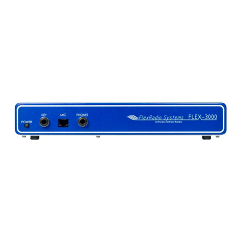
FlexRadio Systems Flex-3000 User manual

®®
Owner's Manual
Version 1.18.0
HF-6m Transceiver
The

SOFTWARE DEFINED RADIO
The FLEX- 000 Owner's Manual
2003−2009 FlexRadio Systems®
All Rights Reserved
Reproduction of this document in any form is expressly forbidden unless explicitly
authorized by FlexRadio Systems.
Information contained in this document may contain technical inaccuracies or typographical
errors. Information may be changed or updated without notice. FlexRadio Systems may
ma e improvements and/or changes in the materials at any time without notice.
All materials are provided "as is". FlexRadio Systems ma es no representations or
warranties, expressed or implied to the accuracy of the copyrighted materials. FlexRadio
Systems will not be liable for any direct, indirect, special or consequential damages arising
out of any use of the document.
FlexRadio Systems is a registered trademar of Bronze Bear Communications, Inc. DBA
FlexRadio Systems.
The FlexRadio Systems Waves Design (logo), SDR-1000, FLEX-3000 and the FLEX-3000
logo, FLEX-5000 and the FLEX-5000 logo, FlexWire, Clic Tune, MultiRX, PanaFall and
PanaScope are trademar s of FlexRadio Systems.
FlexRadio Systems
13091 Pond Springs Rd #250• Austin, TX 78729
Phone: (512) 535-4713• Fax: (512) 233-5143
Email: sales@flex-radio.com
Editor: Joe de Groot – AB1DO
Printer/Distributor: Peter Mar avage - WA2CWA
i 2003-2009 FlexRadio Systems

Table of Contents
PREFACE.....................................................................................IX
ACKNOW EDGMENTS................................................................XI
USING THIS MANUA IN ITS PDF FORM..................................XIII
1 HARDWARE INSTA ATION.......................................................1
UNPACKING AND DECIDING ON A LOCATION..............................................................1
Contents of the Carton...................................................................................................1
Location Considerations.................................................................................................2
PHYSICAL CONNECTIONS.............................................................................................3
Front Panel...................................................................................................................3
(1) Power Switch....................................................................................................................3
(2) Straight Key or Paddles (KEY)..............................................................................................3
(3) Microphone Connector........................................................................................................4
(4) eadphone Jack................................................................................................................5
Bac Panel...................................................................................................................5
(1) 13.8 VDC Power Socket......................................................................................................5
(2) RF Ground Terminal...........................................................................................................5
(3) Antenna Port.....................................................................................................................5
(4) IEEE 1394 FireWire® Jack...................................................................................................6
(5) PTT Jack...........................................................................................................................6
(6) External Keying Line...........................................................................................................6
(7) Powered Speaker Jack........................................................................................................7
(8) FlexWire™ Peripheral Interface Bus......................................................................................7
INSTALLING AND CONFIGU ING THE FLEX ADIO FI EWI E D IVE .........................8
Switch Off the FLEX-3000 and Install the FireWire Driver...................................................8
Power Up the FLEX-3000 and Install the New Hardware Found..........................................13
Configuring the FlexRadio Driver using the Control Panel..................................................16
Sampling Rate and Buffer Size ...............................................................................................17
Operation Mode....................................................................................................................18
DPC Latency Chec er...................................................................................................19
2 POWERSDR INSTA ATION & SETUP......................................21
UPG ADING F OM AN EA LIE VE SION..................................................................21
POWE SD INSTALLATION........................................................................................21
iii 2003-2009 FlexRadio Systems

T A B E O F C O N T E N T S
POWE SD SETUP WIZA D.......................................................................................26
INITIAL POWE SD CONFIGU ATION.......................................................................30
Transfer of Calibration Data..........................................................................................30
Audio Parameters........................................................................................................32
Audio Mixer................................................................................................................32
COMPLETELY FACTO Y CALIB ATED..........................................................................33
3 FRONT CONSO E.....................................................................35
(1) VFO A...................................................................................................................37
(2) TUNING CONT OLS..............................................................................................37
(3) VFO B...................................................................................................................38
(4 ) MULTIMETE S.....................................................................................................38
RX Meters...................................................................................................................39
TX Meters...................................................................................................................39
(5) BAND SELECTION & BAND STACKING MEMO IES.................................................40
(6) MODE SELECTION.................................................................................................41
(7) FILTE CONT OLS................................................................................................42
Labeled Filter Buttons..................................................................................................42
Variable Filter Buttons..................................................................................................43
(8) MODE SPECIFIC CONT OLS..................................................................................44
Phone Controls ...........................................................................................................44
CW Controls................................................................................................................45
Digital Controls...........................................................................................................47
(9) DISPLAY CONT OLS.............................................................................................47
Screen Controls...........................................................................................................48
Display Selection Controls............................................................................................48
Display Type Descriptions.............................................................................................48
Spectrum.............................................................................................................................49
Panadapter (Panoramic Adapter).............................................................................................49
istogram............................................................................................................................50
Waterfall..............................................................................................................................51
Scope..................................................................................................................................52
Phase..................................................................................................................................52
Panafall...............................................................................................................................53
Panascope............................................................................................................................53
Off......................................................................................................................................53
Cursor and Peak Position........................................................................................................53
(10) MULTI X CONT OLS..........................................................................................54
(11) DSP CONT OLS..................................................................................................54
(12) VFO CONT OLS...................................................................................................55
(13) CPU %................................................................................................................56
(14) STA T/STOP BUTTON.........................................................................................56
(15) MON (MONITO )................................................................................................56
(16) MOX (MANUALLY OPE ATED T ANSMIT)...........................................................57
(17) MUT (MUTE).......................................................................................................57
(18) EC ( ECO D) AND PLAY...................................................................................57
(19) TUN (TUNE)........................................................................................................57
(20) ATU AND BYP.....................................................................................................58
(21) AF (AUDIO F EQUENCY GAIN)...........................................................................58
(22) AGC-T (AGC MAXIMUM GAIN)............................................................................58
(23) D IVE (T ANSMITTE POWE OUTPUT/TUNE POWE ).....................................59
(24) AGC (AUTOMATIC GAIN CONT OL)....................................................................59
iv 2003-2009 FlexRadio Systems

T A B E O F C O N T E N T S
(25) X GAIN.............................................................................................................59
(26) SQL (SQUELCH)..................................................................................................60
(27) DATE/TIME DISPLAY..........................................................................................60
(28) SETUP FO M.......................................................................................................60
(29) – (34) OPE ATING FO MS.................................................................................60
4 SETUP FORM............................................................................61
GENE AL TAB.............................................................................................................63
Hardware Config Sub-Tab.............................................................................................63
FLEX-3000 Config...................................................................................................................................63
Receive Only.........................................................................................................................................63
Radio Model...........................................................................................................................................64
DDS.....................................................................................................................................................64
Options Sub-Tab..........................................................................................................65
Options.................................................................................................................................................66
Process Priority......................................................................................................................................66
Clic Tune Offsets (Hz).............................................................................................................................67
Miscellaneous........................................................................................................................................67
Keyboard..............................................................................................................................................68
Custom Title Text...................................................................................................................................68
Calibration Sub-Tab......................................................................................................69
Filters Sub-Tab............................................................................................................70
AUDIO TAB.................................................................................................................71
Primary Sub-Tab..........................................................................................................71
Buffer Size............................................................................................................................................71
Sample Rate..........................................................................................................................................71
Mic Boost..............................................................................................................................................72
Expert..................................................................................................................................................72
Latency (with Expert chec ed).................................................................................................................72
VAC Sub-Tab...............................................................................................................73
Virtual Audio Cable Setup........................................................................................................................73
Gain (dB)..............................................................................................................................................73
Latency.................................................................................................................................................74
Mono/Stereo..........................................................................................................................................74
Combine VAC Input Channels...................................................................................................................74
Auto Enable...........................................................................................................................................74
Allow PTT to override/bypass VAC for Phone..............................................................................................74
Direct IQ...............................................................................................................................................75
DISPLAY TAB..............................................................................................................76
Spectrum Grid.......................................................................................................................................76
Refresh Rates........................................................................................................................................77
Waterfall...............................................................................................................................................77
Multimeter............................................................................................................................................78
Phase Resolution....................................................................................................................................78
Scope Time Base....................................................................................................................................79
Averaging..............................................................................................................................................79
Polyphase FFT........................................................................................................................................79
DSP TAB.....................................................................................................................80
Options Sub-Tab..........................................................................................................80
Noise Reduction.....................................................................................................................................80
Automatic Notch Filter............................................................................................................................81
Use Pea Readings for TX Meter DSP Values..............................................................................................81
Buffer Size............................................................................................................................................82
Noise Blan er........................................................................................................................................83
Noise Blan er 2......................................................................................................................................83
Window ...............................................................................................................................................83
Image Reject Sub-Tab..................................................................................................85
Expert..................................................................................................................................................85
Receive Rejection...................................................................................................................................86
v 2003-2009 FlexRadio Systems

T A B E O F C O N T E N T S
Transmit Rejection..................................................................................................................................86
Keyer Sub-Tab.............................................................................................................87
CW Pitch...............................................................................................................................................87
Connections..........................................................................................................................................88
Options.................................................................................................................................................88
Signal Shaping.......................................................................................................................................89
Brea In...............................................................................................................................................89
AGC/ALC Sub-Tab........................................................................................................90
AGC.....................................................................................................................................................90
Leveler.................................................................................................................................................91
ALC......................................................................................................................................................91
T ANSMIT TAB...........................................................................................................92
TX Profiles.............................................................................................................................................92
Transmit Filter.......................................................................................................................................93
DC Bloc ...............................................................................................................................................93
Tune.....................................................................................................................................................93
Noise Gate............................................................................................................................................94
VOX.....................................................................................................................................................94
Monitor.................................................................................................................................................95
AM Carrier Level....................................................................................................................................95
Standard TX Profiles...............................................................................................................................95
PA SETTINGS TAB.......................................................................................................96
Gain By Band (dB).................................................................................................................................96
APPEA ANCE TAB ......................................................................................................97
Display Sub-Tab..........................................................................................................97
Overall Display.......................................................................................................................................98
Cursor/Pea Readout..............................................................................................................................98
Panadapter............................................................................................................................................99
General Sub-Tab........................................................................................................100
VFO....................................................................................................................................................101
Band Data...........................................................................................................................................101
Meter Sub-Tab...........................................................................................................102
Original Style.......................................................................................................................................103
Edge Style...........................................................................................................................................103
KEYBOA D TAB........................................................................................................104
CAT CONT OL TAB....................................................................................................105
Cat Control .........................................................................................................................................106
PTT Control..........................................................................................................................................107
DigL/U Returns LSB/USB.......................................................................................................................107
FlexProfiler Installed.............................................................................................................................107
Allow Kenwood AI Command..................................................................................................................107
Test....................................................................................................................................................108
RTTY Offset.........................................................................................................................................109
TESTS TAB................................................................................................................110
Two Tone Test:.....................................................................................................................................110
Audio Balance Test...............................................................................................................................110
Signal Generator..................................................................................................................................111
Enable HW Signal Generator..................................................................................................................112
5 OPERATING FORMS...............................................................113
(29) MEMO Y FO M.................................................................................................114
Save… .....................................................................................................................114
Recall….....................................................................................................................115
(30) WAVE FO M.....................................................................................................116
Playbac .............................................................................................................................................116
Playlist................................................................................................................................................117
Record................................................................................................................................................117
TX Gain (dB)........................................................................................................................................117
Quic Rec and Quic Play......................................................................................................................117
vi 2003-2009 FlexRadio Systems

T A B E O F C O N T E N T S
Record Options..........................................................................................................118
Receive...............................................................................................................................................118
Transmit..............................................................................................................................................118
Sample Rate........................................................................................................................................118
(31) EQUALIZE FO M.............................................................................................119
3-Band Equalizer.......................................................................................................119
10-Band Equalizer.....................................................................................................120
(32) XVT S FO M....................................................................................................121
(33) CWX FO M.......................................................................................................123
Standard CWX Controls..............................................................................................123
CWX Memories....................................................................................................................124
Special Characters...............................................................................................................124
Keyboard and Extended Controls.................................................................................125
Extended CWX Controls........................................................................................................125
Morse Definition Editor.........................................................................................................126
(34) MIXE ..............................................................................................................128
Input..................................................................................................................................................128
Output................................................................................................................................................128
VOLTAGE AND TEMPE ATU E INFO MATION..........................................................129
6 OPERATION............................................................................131
POWE -UP P OCEDU E...........................................................................................132
POWE -DOWN P OCEDU E.....................................................................................132
TUNING METHODS....................................................................................................133
Spectrum Drag and Click......................................................................................................133
Mouse Wheel......................................................................................................................133
Mouse Wheel over.............................................................................................................133
Spectrum Click Tuning..........................................................................................................133
Keyboard Keys....................................................................................................................134
USB Tuning Knob.................................................................................................................134
VOICE OPE ATION...................................................................................................135
CW OPE ATION........................................................................................................138
Initial Settings...........................................................................................................139
Internal Keyer...........................................................................................................140
External Keyer...........................................................................................................142
CWX Form................................................................................................................142
Third Party Program...................................................................................................143
DIGITAL OPE ATION...............................................................................................146
CAT Control Setup.....................................................................................................149
Install VCOM.......................................................................................................................149
Configure the VCOM Port Pairs...............................................................................................155
Configure PowerSDR CAT Control...........................................................................................157
Configure PowerSDR Keyer Connections..................................................................................158
Virtual Sound Connection............................................................................................159
Create the Virtual Audio Cables.............................................................................................159
Setup VAC in PowerSDR.......................................................................................................161
Setting up Third Party Digital Programs........................................................................162
Using MixW with PowerSDR...................................................................................................162
Programs Needing to Connect to the Default Sound Device........................................................166
7 SPECIFICATIONS AND ARCHITECTURE................................169
FLEX-3000 T ANSCEIVE SPECIFICATIONS............................................................169
FLEX-3000 A CHITECTU E.......................................................................................171
vii 2003-2009 FlexRadio Systems

T A B E O F C O N T E N T S
DECLA ATIONS OF CONFO MITY.............................................................................172
FCC..........................................................................................................................172
EU Compliance..........................................................................................................172
A BUFFERS AND SAMP E RATE................................................173
FILTE EFFECTS.......................................................................................................173
LATENCY EFFECTS....................................................................................................175
UNDE LYING THEO Y..............................................................................................175
B UPDATING THE F EX-3000 FIRMWARE.................................179
AUTOMATICALLY......................................................................................................179
MANUALLY...............................................................................................................179
Download and Extract the Firmware.............................................................................179
Update the Firmware..................................................................................................180
C OPTIMIZING THE AGC...........................................................183
D WINDOW FUNCTIONS............................................................185
viii 2003-2009 FlexRadio Systems

Preface
Welcome to the exciting world of software defined radio. The FLEX-3000™ 1 software defined
transceiver is the culmination of many years of experience gained with FlexRadio's ground brea ing
series of transceivers. The experience gained and lessons learned have resulted in an SDR platform that
is truly state of the art, yet extremely compact. And unli e most other transceivers, which once
acquired, rarely if ever change, the FLEX-3000 will continue to (rapidly) evolve, offering future
capabilities currently only dreamed of.
This operating manual attempts to both guide the user step by step through the setup process (both
hardware and software) and to act as a reference once the radio has been set up. Additionally, the
freely downloadable PowerSDR software will install with default settings that, in most cases, will require
little adjustment. Any adjustments that you ma e are automatically saved and can be imported into an
updated version of the software.
Due to the nature of the FLEX-3000, the largest part of this operating manual, by far, will refer to
software. The operating manual has numerous screenshots of windows and forms to detail the various
steps. Although the manual describes the latest official release of the PowerSDR software, you may
occasionally notice an earlier version identified in the title bar of a screenshot. This is because FlexRadio
Systems® has decided to only update a screenshot if it changes. If you have any ideas on how to
improve the FLEX-3000, please feel free to contact us, or better still, to join our email reflector (see
http:// c.flex-radio.com/KnowledgebaseArticle50024.aspx). Not only is the FLEX-3000 a software
defined radio; it is also a user defined radio.
FlexRadio Systems is committed to ensuring that your experience with the FLEX-3000 will be one of the
most enjoyable you have with Ham radio. If you have any questions, issues or problems operating
PowerSDR and/or the FLEX-3000, you may be able to find the solution on the Support Pages of our
website (http://support.flex-radio.com/), in our Knowledge Center (http:// c.flex-
radio.com/search.aspx), our Forum (http://forums.flex-radio.com/), or through our highly active email
reflector (http:// c.flex-radio.com/KnowledgebaseArticle50024.aspx). If none of these sources provide
you the assistance required, please contact FlexRadio Systems using the information provided on the
Contact Page of our website (http://www.flex-radio.com/About.aspx?topic=contactus).
1 FlexRadio Systems is a registered trademar of Bronze Bear Communications, Inc. DBA FlexRadio Systems. The FlexRadio
Systems Waves Design (logo), SDR-1000, FLEX-3000 and the FLEX-3000 logo, FLEX-5000 and the FLEX-5000 logo, FlexWire,
Clic Tune, MultiRX, PanaFall and PanaScope are trademar s of FlexRadio Systems.
ix 2003-2009 FlexRadio Systems

Acknowledgments
FlexRadio Systems could not be as successful, nor could the FLEX-3000 radio be what it is today
without the many selfless contributions from our users all over the world. These contributions have
spanned and continue to span improvements to our hardware and software, ranging from bug reports
and feature requests to actual design and implementation of certain functionality.
Identifying contributors by name would only ris leaving out others with equally valuable contributions.
We therefore wish to suffice with a heartfelt than you for your support and continued commitment.
[The rest of this page has been left blan intentionally]
xi 2003-2009 FlexRadio Systems

Using This Manual in its PDF Form
If you are viewing this manual on your computer screen, you can use a combination of built-in features
of Adobe® Reader®1 as well as the many cross-references and hyperlin s within the text:
To find a word within the manual, type ctrl + F on your eyboard (or in the menu clic Edit -
Find), enter the desired word in the text box that opens and clic Next.
To jump to a chapter or section in the manual, clic on the corresponding Boo mar , shown to
the left of this page. (If not shown, clic on the vertical tab labeled Bookmarks). To ma e
them as useful as possible, we have made the boo mar s very detailed.
Clic on the “Previous View” arrow to go bac to a previously viewed page. (Alternatively, in the
menu, clic View – Goto – Previous View, or on your eyboard type Alt + Left Arrow).
oSimilarly clic on the “Next View” arrow to go forward to a subsequently viewed page.
(Alternatively, in the menu, clic View – Goto – Next View, or on your eyboard type
Alt + ight Arrow).
Within the text there are many cross-references. Although not obvious, these are all hyperlin s
within the manual. Clic on the referenced Table n, Figure n, above, below or page n (bold
indicates the hyperlin ) and you will immediately jump to the referenced Table/Figure/page of
the manual.
oTo return to where you came from, use the “Previous View” arrow.
Within the text there are also external hyperlin s, shown in blue and underlined. Clic on these
to open your browser and view the referenced website page. Many of these relate to articles in
our expansive Knowledge Center.
oIf the hyperlin has been previously clic ed, it will be shown in magenta instead of blue.
[The rest of this page has been left blan intentionally]
1 Adobe and Reader are registered trademar s of Adobe Systems, Inc.
xiii 2003-2009 FlexRadio Systems

1
Hardware Installation
To install the Flex-3000, you will need to:
Unpac and decide on a location
Physically connect the radio to a power supply, antenna, microphone, ey, etc. Although not
necessary, you should preferably ma e all these connections in advance. However, you must at
least connect the FLEX-3000 to a 13.8VDC power supply and connect the IEEE 1394 FireWire® 1
cable.
Install and configure the FlexRadio FireWire Driver This driver is required to enable the
computer to interface with the FLEX-3000.
Unpacking and Deciding on a Location
Contents of the Carton
Inside the carton you should find the following items:
Table 1: Contents of Carton for each FLEX-3000 Model
Item
FLEX-3000 Transceiver
6-pin to 6-pin FireWire cable (6 feet)2
Unterminate 12 AWG power cable (4 feet)
PL259/BNC a apter
Quick Start Gui e
CD ROM/USB Flash Drive with Owner's manual, Quick Start Gui e, PowerSDR
1.18 or later, FlexRa io FireWire Driver
(Other items may be included that are not listed above)
The FLEX-3000 power cable is unterminated at one end so that you can adapt it to various DC power
connectors, such as Anderson Power Poles, Banana plugs, screw terminals or spade lugs. Connect the 2
red wires to the positive terminal and the 2 blac wires to the negative terminal of your power supply.
1 FireWire and the FireWire logo are registered trademar s of Apple, Inc., under license.
2 You may need to acquire a 4-pin to 6-pin cable if using a laptop
1 2003-2009 FlexRadio Systems
Chapter
1

H A R D W A R E I N S T A A T I O N C H A P T E R 1
Note 1: Do not apply power to the FLEX-3000 until you are instructed to do
so.
Note 2: Retain the FLEX-3000 pac aging for future use. This pac aging was
specially designed for the radio to prevent damage which may occur
during shipping. If you ever need to ship your FLEX-3000 anywhere,
especially bac to FlexRadio Systems, this is the preferred pac aging
to use.
Location Considerations
To facilitate integrating your FLEX-3000 into your shac you may want to consider the following:
Place your FLEX-3000 in close proximity to your computer . It is best to use the shortest
FireWire cable possible to connect to your computer to minimize data errors and limit possible
RFI getting into the computer. High quality, quad-shielded FireWire cables up to 10m in length
have been used successfully with the FLEX-3000.
Ensure convenient access to the bac panel . The FLEX-3000 bac panel is where several of your
connections will be made. Having easy access to the bac panel without moving the
transceiver is optimal while getting started.
Avoid placing the FLEX-3000 in direct sunlight . Placing the transceiver in direct sunlight will
increase the ambient temperature inside the chassis (especially while transmitting) and ma e
the high volume cooling fans' job more difficult.
Heed air flow requirements . Air enters from the sides and is expelled through the rear vent for
optimal cooling. Do not bloc these vents since doing so will reduce the cooling efficiency.
Avoid contact with liquids . Although this is usually not a problem unless you are operating
maritime mobile, accidental spills of liquids on the FLEX-3000 could result in voiding the
warranty. Placing the FLEX-3000 away from food and drin s is highly recommended.
[The rest of this page has been left blan intentionally]
22003-2009 FlexRadio Systems

H A R D W A R E I N S T A A T I O N C H A P T E R 1
Ph sical Connections
We will now discuss first the front panel and then the bac panel connections.
Front Panel
(1) Power Sw tch
The FLEX-3000 uses a delayed start push-to-latch/push-to-release switch to power up the radio.
To turn on the radio, push the switch in fully to latch it in the on position. After a few seconds
you will hear the power relay clic and see the blue LED illuminate to indicate that the radio is
powered up.
To turn off the radio, again push the button fully to unlatch it in the off position.
Note 1: Ma e sure the FLEX-3000 is turned on and then wait 10-15 seconds
before starting PowerSDR. Otherwise, PowerSDR will indicate a
communication error and offer the option to run in Demo mode. Clic
No to close PowerSDR, turn on the FLEX-3000 and restart PowerSDR.
Note 2: Ma e sure PowerSDR is shut-down before turning off the radio.
Otherwise, close PowerSDR and power cycle the FLEX-3000 (turn on,
off and on again) and restart PowerSDR.
(2) Stra ght Key or Paddles (KEY)
For CW operation, the ¼” TRS KEY jac will accept a TRS plug for operating a eyer with paddles or a
TRS/TS plug for a straight ey. The pin-out is shown in Table 2 below.
Table 2: Key Jack P n-Out
Connector
Keyer
Signal
Straight
Key
Tip Dot Key
Ring Dash N/C
Sleeve Common Common
32003-2009 FlexRadio Systems
F gure 1: FLEX-3000 Front Panel

H A R D W A R E I N S T A A T I O N C H A P T E R 1
Note: Although not necessary, if you prefer to connect your paddles to a
serial port on your PC you may do so using the pin-out shown in
Table 3.
Table 3: PC Ser al Port P n-Out
Serial
Port Pin* Keyer Signal
4 (DTR) Common
6 (DSR) Dot
8 (CTS) Dash
* Assumes a 9-Pin connector
(3) M crophone Connector
The 8-pin RJ-45 connector offers the ability to connect a microphone and to ey the radio via a PTT
line. The pin-out is shown in Figure 2 below1. To engage PTT, pin 6 must be grounded to pin 7 (Shield
Ground) and not to pin 4, which is the microphone ground.
Note: The pins designated as Up, Down and Fast enable the use of (mobile
style) microphones that have these buttons built in to them. Up and
Down will tune the frequency up or down respectively at the rate set
by Tune Step in PowerSDR (see page 37). The Fast button switches
this Tune Step between 50Hz and 1 Hz.
Although the FLEX-3000 will wor well with many types of microphones, it is conveniently wired to
enable the use of microphones such as the Yaesu MH-31, that include buttons for Up, Down and Fast.
[The rest of this page has been left blan intentionally]
1 The pin-out is similar to that normally found on Yaesu mobile radios
42003-2009 FlexRadio Systems
F gure 2: P n-out of the MIC Jack

H A R D W A R E I N S T A A T I O N C H A P T E R 1
(4) Headphone Jack
Accepts headphones with standard 1/4” stereo (TRS) plug. Recommended ratings for headphones are
40 mW into 16 Ohm load (typ) with a 1% THD+N. Higher impedance headphones will also wor .
Note: Lower impedance headphones and headphones using a mono plug
can result in popping audio as soon as PowerSDR is started.
Back Panel
(1) 13.8 VDC Power Socket
The FLEX-3000 requires a stable 13.8 VDC power source rated for at least 20 Amps and 25 Amps pea
for proper operation. Supplied with your radio was an unterminated 4-pin eyed Molex type power
connector and cable set. Terminate this cable in the appropriate connector (if needed) for your DC
power source such as Anderson PowerPoles®, banana plugs, spade or ring lugs, or tinned ends for
screw terminals. Connect the 2 red wires to the positive terminal and the 2 blac wires to the negative
terminal of your power supply. The Molex type connector is inserted into the white Molex receptacle
labeled -13.8 VDC+.
(2) RF Ground Term nal
Connect to the single point ground system in your shac . Alternatively, if you have no single point
grounding system, ground the FLEX-3000 to the metal chassis of your computer with a low impedance
ground strap, such as a 1” braid or copper strip (the screws that hold the computer power supply in
place ma e an excellent grounding point).
(3) Antenna Port
Connect a 50 Ohm antenna or dummy load to the BNC antenna port. Alternatively the internal antenna
tuner can be used to match an antenna with a different iimpedance.
[The rest of this page has been left blan intentionally]
52003-2009 FlexRadio Systems
F gure 3: FLEX-300 Back Panel

H A R D W A R E I N S T A A T I O N C H A P T E R 1
(4) IEEE 1394 F reW re
®1
Jack
The FLEX-3000 has a 400 Mb/s 6-pin IEEE 1394 FireWire jac . This is a 1394a connection, not the
1394b (FireWire 800) type which run at 800 Mb/s. Connect the ferrite core end of the supplied 6-pin
FireWire cable to this jac and connect the other end to your computer’s FireWire jac (the host
controller).
WA NING! DO NOT FO CE THE FI EWI E CONNECTO IN UPSIDE
DOWN. DOING SO WILL DEST OY THE ADIO'S FI EWI E
PO T.
CAUTION: Do not remove the ferrite cores as they are required for CE
compliance and to minimize RFI at this ingress point.
Note 1: Even though the 1394b standard is supposedly downward compatible
(9-pin to 6- or 4-pin cables are used), you should preferably only use
1394a host adapters to connect to the FLEX-3000. Please also refer
to the Knowledge Center article Selecting igh Performance FireWire
Cards for FlexRadio Transceivers (search for firewire card in our
Knowledge Center at http:// c.flex-radio.com/search.aspx).
(5) PTT Jack
Connect to external hardware devices such as foot pedals or hand switches to ey the rig. The
transmitter will be engaged when the center conductor is grounded.
(6) External Key ng L ne
This eying line, which can be given a delay, can be used to ey an external device such as a linear
power amplifier or transverter.
The eying line uses an open collector Darlington transistor switch that is rated at 400mA, 50VDC
maximum. To ensure that your amplifier eying circuit does not damage the Darlington transistor
switch, it is safest (even for modern amplifiers) to insert the circuit shown in Figure 4 below between
the TX port and your amplifier.
[The rest of this page has been left blan intentionally]
1 FireWire is a registered trademar of Apple, Inc.
62003-2009 FlexRadio Systems

H A R D W A R E I N S T A A T I O N C H A P T E R 1
F gure 4: Protect ve PTT C rcu t Between TX Out and Ampl f er
(7) Powered Speaker Jack
This standard 1/8” TRS jac provides line-level (-10dBV, 600 Ohms) receive - not computer - audio.
Connect this jac to an external audio amplifier, to computer-type powered spea ers or any other
external equipment that accepts line-level audio input. This jac provides two-channel (stereo) audio to
enable binaural audio and MultiRX™ 1 The audio level can be set on the FLEX-3000 Mixer Form (see
page 128).
For more information on powered spea ers used with FlexRadio products, refer to the Knowledge
Center article What Kind of Spea ers Should I buy for my SDR? (search for speaker in our Knowledge
Center at http:// c.flex-radio.com/search.aspx).
(8) FlexW re™ Per pheral Interface Bus
FlexWire2 is an intelligent, high speed, bi-directional communications interface that allows PowerSDR to
communicate with a host of peripheral devices such as antenna tuners, rotor controllers, band
switchers, etc. A family of FlexWire peripherals will be forthcoming from FlexRadio Systems. This is not
another “CAT” port, but an industry standard bidirectional communications bus based on the I2C
(pronounced “I squared C”) protocol along with AF I/O lines.
Table 4: FlexW re Connector P n-Out
Pin # Signal Diagram
1Groun
2Line In
3(Blocke Pin)
4Interrupt (/INT 1)
5Groun
6I2C Clock (SCL)
7I2C Data (SDA)
8+13.8V, 1A max
9Line Out (in parallel
with RCA Line Out)
Table 4 above Shows the FlexWire connector pin-out. Complete specifications and the programming
interface will be published to allow home brew and third-party add-on products.
1MultiRX is a trademar of FlexRadio Systems
2 FlexWire is a trademar of FlexRadio Systems.
72003-2009 FlexRadio Systems

H A R D W A R E I N S T A A T I O N C H A P T E R 1
CAUTION: Do NOT attempt to connect a PC serial port to the FlexWire connector
(pin 3 has been bloc ed to stop this). Doing so may void your
warranty and severely damage your FLEX-3000.
Installing and Configuring the FlexRadio FireWire Driver
Switch Off the FLEX-3000 and Install the FireWire Driver
Note 1: To install the FlexRadio FireWire Driver, you must at least connect the
FLEX-3000 to a 13.8VDC power supply and an IEEE 1394 FireWire
computer port.
Note 2: If there is a (Edirol FA-66 or Presonus Firebox) sound card connected
to the same FireWire host controller you are planning to use with the
FLEX-3000, disconnect it until the installation is complete and the
FLEX-3000 is fully operational.
WA NING! It has been reported that data corruption occurred when
trying to use a FireWire hard disk. We do not recommend that
you have a FireWire hard disk connected to the same FireWire
controller (bus) as the FLEX-3000.
Also, do not connect both a FLEX-3000 and a FLEX-5000 to the
same computer. The drivers cannot differentiate between the
two and erratic behavior may occur.
Download the FlexRadio FireWire Driver at http://support.flex-radio.com/Downloads.aspx?id=165 or
from the downloads page (http://support.flex-radio.com/Downloads.aspx?fr=1) of our website and
save the zip file to a convenient location on your computer. Then go to the saved zip file and extract its
contents.
Before proceeding with the installation, ma e sure the power switch on the FLEX-3000 is turned off
(blue LED is off, see Figure 1 on page 3). It is also a good idea to close all other applications.
Double clic on the extracted driver installation file to open the FlexRadio Setup Wizard (Figure 5).
[The rest of this page has been left blan intentionally]
82003-2009 FlexRadio Systems

H A R D W A R E I N S T A A T I O N C H A P T E R 1
Clic the Next button to continue to Figure 6 1.
[The rest of this page has been left blan intentionally]
1 All screenshots in this manual are as they would appear when using the Microsoft Windows XP operating system. The
screenshots may loo slightly different when using Microsoft Vista, but the steps are the same.
92003-2009 FlexRadio Systems
F gure 5: FlexRad o Dr ver Setup W zard
Other manuals for Flex-3000
1
Table of contents
Other FlexRadio Systems Transceiver manuals
FlexRadio Systems
FlexRadio Systems Flex-3000 User manual
FlexRadio Systems
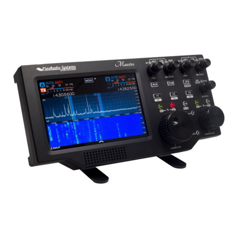
FlexRadio Systems FLEX-6000 Signature Series User manual
FlexRadio Systems
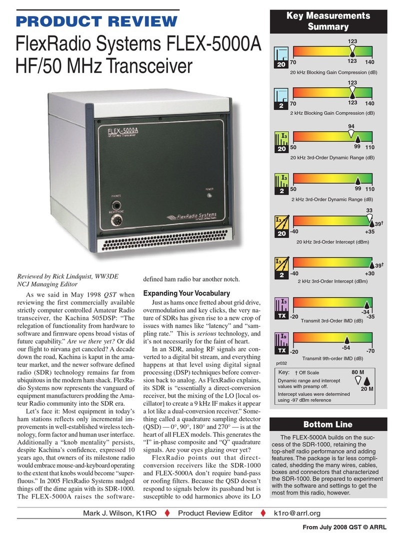
FlexRadio Systems FLEX-5000A User manual
FlexRadio Systems
FlexRadio Systems FLEX-6000 Signature Series Quick user guide

FlexRadio Systems
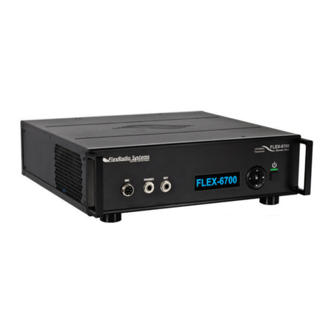
FlexRadio Systems FLEX-6000 Signature Series User manual
FlexRadio Systems
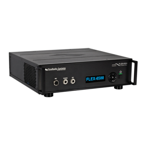
FlexRadio Systems FLEX-6000 Signature Series User manual
FlexRadio Systems
FlexRadio Systems FLEX-5000C User manual
FlexRadio Systems
FlexRadio Systems FLEX-1500 User manual
FlexRadio Systems
FlexRadio Systems SDR-1000 User manual
FlexRadio Systems
FlexRadio Systems FLEX-5000 Series User manual
