Flight Display Systems FD932DVD-BLU User manual

Document Number:
MAN –FD932DVD-BLU
Rev:
Q
Revision Date:
12/01/2011
Page 1 of 35
FD932DVD-BLU & FD932DVD-BLU Ver CV
Installation and Operation Manual
Blu-ray/DVD/CD/MP3 Player, Component Video
TECHNICAL SUPPORT
678-867-6717, or
www.FlightDisplay.com
All manuals and user guides at all-guides.com
all-guides.com
Document Number:
MAN – FD932DVD-BLU
Rev:
Q
Revision Date:
12/01/2011
Page 2 of 35
FD932DVD-BLU & FD932DVD-BLU Ver CV
BLU-RAY/DVD/CD/MP3 PLAYER, Component Video
© 2009 Flight Display Systems. All Rights Reserved.
Flight Display Systems
1765 Grassland Parkway
Alpharetta, GA 30004
678-867-6717 Phone
678-867-6742 Fax
sales@flightdisplay.com
www.flightdisplay.com
For the most current copy of all product manuals, please visit our website at
www.flightdisplay.com
All manuals and user guides at all-guides.com
Document Number:
MAN – FD932DVD-BLU
Rev:
Q
Revision Date:
12/01/2011
Page 3 of 35
Table of Contents
General Information......................................................................................................................4
1. Features ..............................................................................................................................4
2. Front View..........................................................................................................................4
3. Ventilation..........................................................................................................................5
Specifications................................................................................................................................6
Installation Instructions .............................................................................................................6
1. Power ..................................................................................................................................6
2. Front Panel .........................................................................................................................7
3. Rear Panel output/Mechanical.......................................................................................7
4. Assembly of Connector Spring Latch ............................................................................8
Video Wiring Suggestions .........................................................................................................9
1. Audio Wiring.....................................................................................................................9
2. Power and Ground Wiring............................................................................................10
HDMI ...........................................................................................................................................10
Pinout for DB-25 Receptacle ....................................................................................................12
Ship Kit Items.............................................................................................................................14
RS485 Controls ...........................................................................................................................15
Infrared Control .........................................................................................................................19
Operating Instructions..............................................................................................................20
Remote Control...........................................................................................................................24
Instructions for Region Setup .................................................................................................26
Region Codes ..............................................................................................................................27
How to Update Firmware .........................................................................................................28
Technical Drawing.....................................................................................................................30
Trouble Shooting .......................................................................................................................31
Technical Support......................................................................................................................32
All manuals and user guides at all-guides.com
Document Number:
MAN –FD932DVD-BLU
Rev:
Q
Revision Date:
12/01/2011
Page 4 of 35
Instructions for Continued Airworthiness ...........................................................................32
Warranty ......................................................................................................................................33
Log of Revisions.........................................................................................................................34
General Information
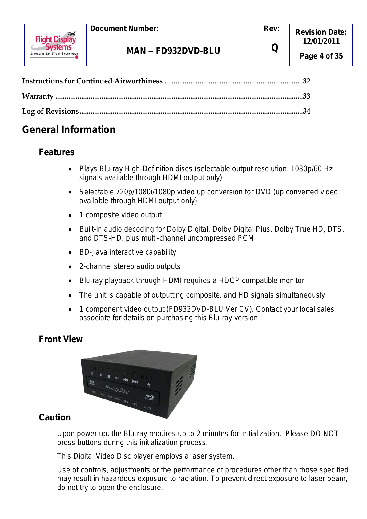
Features
Plays Blu-ray High-Definition discs (selectable output resolution: 1080p/60 Hz
signals available through HDMI output only)
Selectable 720p/1080i/1080p video up conversion for DVD (up converted video
available through HDMI output only)
1 composite video output
Built-in audio decoding for Dolby Digital, Dolby Digital Plus, Dolby True HD, DTS,
and DTS-HD, plus multi-channel uncompressed PCM
BD-Java interactive capability
2-channel stereo audio outputs
Blu-ray playback through HDMI requires a HDCP compatible monitor
The unit is capable of outputting composite, and HD signals simultaneously
1 component video output (FD932DVD-BLU Ver CV). Contact your local sales
associate for details on purchasing this Blu-ray version
Front View
Caution
Upon power up, the Blu-ray requires up to 2 minutes for initialization. Please DO NOT
press buttons during this initialization process.
This Digital Video Disc player employs a laser system.
Use of controls, adjustments or the performance of procedures other than those specified
may result in hazardous exposure to radiation. To prevent direct exposure to laser beam,
do not try to open the enclosure.
All manuals and user guides at all-guides.com

Document Number:
MAN – FD932DVD-BLU
Rev:
Q
Revision Date:
12/01/2011
Page 5 of 35
DO NOT STARE INTO BEAM.
Ventilation
Slots and openings in the player are provided for ventilation, to ensure correct operation of
the product. These openings protect the unit from overheating and must not be blocked or
covered. It is recommended that the player have a minimum 1-inch of ventilation around
the unit and not be placed in a location that does not have circulating air.
Disc Tray
Keep your fingers well clear of the disc tray as it is closing. Neglecting to do this may cause
serious personal injury and damage to the product.
The following types of discs are supported
Notes:
• Writeable discs (DVD-RAM, DVD-RW, DVD-R) must be finalized, VR-mode only.
This Blu-ray disc player supports discs that are compatible with DVD-RAM Standard Version 2.0.
Playback may not work for some types of discs, or when specific operations, such as angle change
and aspect ratio adjustment, are being performed. Information about the discs is written in detail on
the box. Please refer to this if necessary.
Do not allow the disc to become dirty or scratched. Fingerprints, dirt, dust, scratches or deposits of
cigarette smoke on the recording surface will disrupt the proper operation and may prevent playback
of the disc.
CD-R/-RW, DVD-RAM/-RW/-R recorded with UDF or ISO9660 format can be played back.
MP3 files must be written to the disc with an .mp3 file extension in order to be recognized and played
back properly.
High bitrate or variable bitrate .mp3 and .wma files may not play back correctly.JPEG picture files
must be written to the disc with a .jpeg or .jpg file extension in order to be recognized and played back
properly.
Due to differing menu formats among Blu-ray and standard DVD-videos, the enter key may be required to
start some movies at the home screen, while the play key is required to start other movies at the home
screen. This can occur on both Blu-ray and standard DVD movies. If a movie does not start when
prompted, try using the enter button if play does not respond, or press the play button if enter does not
respond.
All manuals and user guides at all-guides.com

Document Number:
MAN – FD932DVD-BLU
Rev:
Q
Revision Date:
12/01/2011
Page 6 of 35
Specifications
Dimensions
7.00” (W) x 2.60” (H) x 8.57” (D)
Dimensions (with mounting
brackets)
8.25” (W) x 2.60” (H) x 9.27” (D)
Operating Temperature
0-50° C (32-122° F)
Output
HDMI with 1080p
(with locking Type A connector VER
1.3) Composite Video NTSC (BNC
connector) Audio 2-channnels
Controls through RS-485
Audio Output
2 Vrms, 80dB Dynamic Range
Power
28VDC, 750mA
Remote Control
IR, included& 12’ IR Extension Cable
Playback Media
BD-ROM/DVD-ROM/DVD-R
DVD-RW/Audio/CD/CD-R/CD-RW
Playback Formats
VC-1/MPEG2/JPEG/MP3
Weight
2lbs 13 oz
DVD
4HZ to 22KHZ (48KHZ sampling)
4HZ to 44KHZ (96KHZ sampling)
CD-AUDIO
4HZ to 22KHZ, S/N ration: 90dB
Dimensions
7.00” (W) x 2.60” (H) x 8.57” (D)
Dimensions (with mounting
brackets)
8.25” (W) x 2.60” (H) x 9.27” (D)
DO-160 TESTING
Section 21, Category B
Parts Manufacturer Approval
FD932DVD-BLU: PMA Approved
FD932DVD-BLU Ver CV: Non-PMA
Approved
Installation Instructions
All cabin entertainment equipment, such as the FD932DVD-BLU & FD932DVD-BLU Ver CV, should
be installed on a non-essential bus and have a dedicated circuit breaker. It is a requirement that a
switch be installed in the cockpit so that the pilot can de-energize the entertainment system should it
become necessary. The unit includes two angle mounting brackets which can be installed at the top
or bottom on each side of the player. The player also includes a strain relief bracket which is used
to secure the HDMI cable in place with a 3/16” cable tie. NOTE: Care should be taken to ensure
the unit is not installed in an area with poor ventilation, or in an area with excessive heat.
NOTE: THIS UNIT CANNOT BE MOUNTED FACE UP.
All manuals and user guides at all-guides.com
all-guides.com
Document Number:
MAN – FD932DVD-BLU
Rev:
Q
Revision Date:
12/01/2011
Page 7 of 35
Power
The FD932DVD-BLU & FD932DVD-BLU Ver CV requires 28VDC rated at 750mA to function.
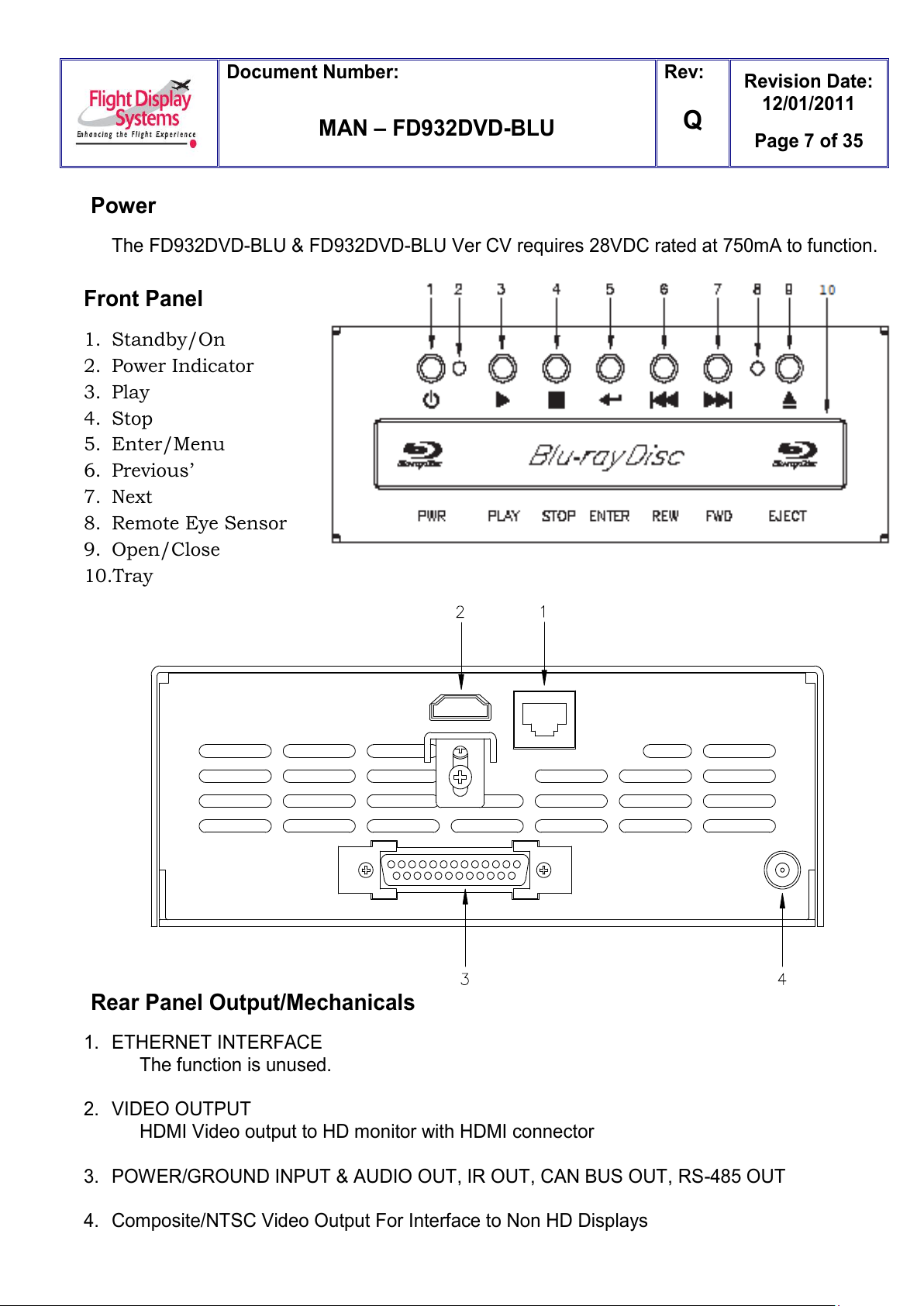
Front Panel
1. Standby/On
2. Power Indicator
3. Play
4. Stop
5. Enter/Menu
6. Previous’
7. Next
8. Remote Eye Sensor
9. Open/Close
10.Tray
Rear Panel Output/Mechanicals
1. ETHERNET INTERFACE
The function is unused.
2. VIDEO OUTPUT
HDMI Video output to HD monitor with HDMI connector
3. POWER/GROUND INPUT & AUDIO OUT, IR OUT, CAN BUS OUT, RS-485 OUT
4. Composite/NTSC Video Output For Interface to Non HD Displays
All manuals and user guides at all-guides.com
Document Number:
MAN – FD932DVD-BLU
Rev:
Q
Revision Date:
12/01/2011
Page 8 of 35
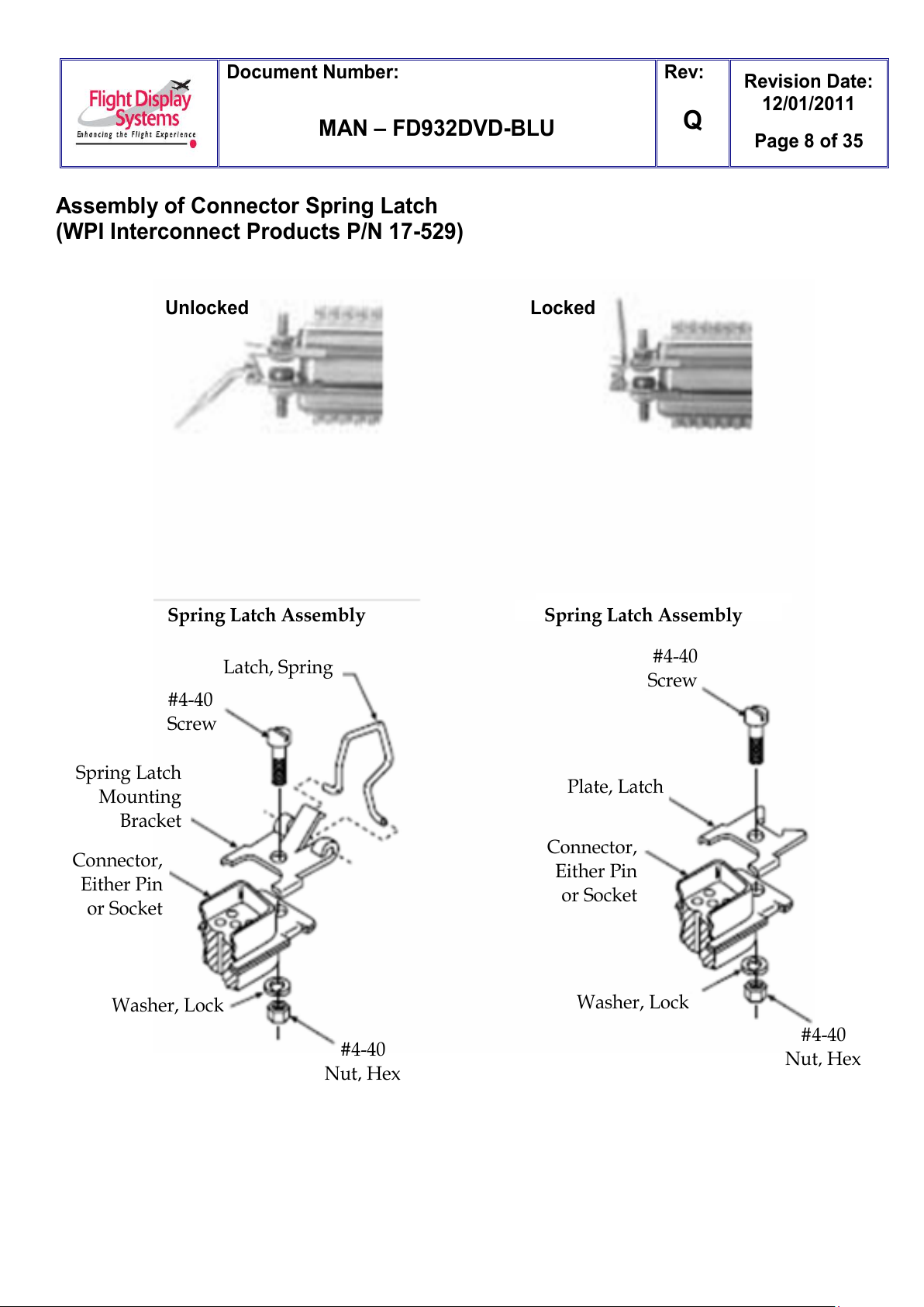
Assembly of Connector Spring Latch
(WPI Interconnect Products P/N 17-529)
Unlocked
Locked
Spring Latch Assembly
Latch, Spring
#4-40
Screw
#4-40
Screw
Plate, Latch
Connector,
Either Pin
or Socket
Washer, Lock
#4-40
Nut, Hex
#4-40
Nut, Hex
Washer, Lock
Connector,
Either Pin
or Socket
Spring Latch
Mounting
Bracket
Spring Latch Assembly
All manuals and user guides at all-guides.com

Document Number:
MAN – FD932DVD-BLU
Rev:
Q
Revision Date:
12/01/2011
Page 9 of 35
Video Wiring Suggestions
Avoid routing video wiring parallel to:
AC wiring
Strobe wiring
DC motor supply cables
Inverter cabling
Or any other potential noise source.
Recommended cable for composite is PIC 75 Ohm Coax, P/N V75268. This is a lightweight,
flexible, and low signal loss cable which meets FAA requirements of FAR 23.1359(d), FAR
25.853(a) and FAR 25.869(a)(4).
Similar aviation coaxial cable can be used from other vendors, as well.
Some aircraft are prone to AC noise - we recommend adding to the composite source a
75Ohmvideo isolation transformer such as Deerfield Laboratory, Inc. Part No. 162-1
(www.deerfieldlab.com, (650) 632-4090). In most cases this should be added to the video
output of the source.
Audio Wiring for Use with Single Ended Audio Inputs. (ie: FDACS)
For best performance, use four individual wires or two twisted pairs in a shielded cable.
The four audio wires would be connected to Left +, Left -, Right +, Right -.
All four wires will run from the Blu-ray player to the destination.
Left + and Right + connect to the Left and Right signal inputs respectively.
Left – and Right – will join together at the destination and connect to the receiving
equipment‟s audio return pin. The shield will be connected to the fuselage at one place
only.
All manuals and user guides at all-guides.com

Document Number:
MAN – FD932DVD-BLU
Rev:
Q
Revision Date:
12/01/2011
Page 10 of 35
Audio Wiring for Use with Balanced Audio Inputs.
For best performance, use two twisted pairs in a shielded cable or two individual
shielded twisted pairs.
One pair is connected to Left + and Left -. The other pair connects to Right + and Right -
All four wires will run from the Blu-ray player to the destination.
Left + and Left – connect to the receiving equipment‟s Left channel input.
Right + and Right – connect to the receiving equipment‟s Right channel input.
The shield will be connected to the fuselage at one place only.
NOTE: The FD932DVD-BLU has high impedence balanced outputs instead of the more
popular low impedence inputs. This is usually not a problem. External audio level pads may be
installed at the installer‟s discretion.
Power and Ground Wiring
22 AWG or larger wire is recommended for Power and Ground applications.
HDMI
HDMI (High-Definition Multimedia Interface) defines the protocol and electrical
specifications for the signalling, pin-out, electrical, and mechanical requirements of cable
and connectors used for transmitting High-Definition content. The Type A HDMI connector
(shown below) has 19 pins with bandwidth to support all SDTV, EDTV, and HDTV modes.
The plug's outside dimensions are 13.9 mm wide by 4.45 mm high.
ECS manufactures an HDMI cable that is terminated at the factory. It is ordered as part
number 600-19786-XXX, where XXX is the length in inches for the desired cable.
All manuals and user guides at all-guides.com

Document Number:
MAN – FD932DVD-BLU
Rev:
Q
Revision Date:
12/01/2011
Page 11 of 35
NOTE: On the following Pinout pages, Pin 14, 15, 16 are reserved for CAN BUS
integration. The FD932DVD-BLU & FD932DVD-BLU Ver CV is only intended to
easily integrate with the Flight Display Systems Select CMS. If more information
regarding the CAN BUS integration with this device is required please contact
Flight Display Systems Technical Support at 678-867-6717.
All manuals and user guides at all-guides.com
all-guides.com

Document Number:
MAN – FD932DVD-BLU
Rev:
Q
Revision Date:
12/01/2011
Page 12 of 35
Pinout for DB-25 Receptacle (For current Blu-ray players with embedded serial
CODE: X10629XXX or X70014XXX,X70024XXX and Greater)
Connector P/N: DB-F25CH
Crimp Contacts P/N: M39029/63-368 or Equivalent
All manuals and user guides at all-guides.com

Document Number:
MAN – FD932DVD-BLU
Rev:
Q
Revision Date:
12/01/2011
Page 13 of 35
FD932DVD-BLU Ver CV (Component Video)
Pinout for DB-25 Receptacle (For current Blu-ray players with embedded serial
CODE: X10631XXX and Code X70018XXX)
Connector P/N: DB-F25CH
Crimp Contacts P/N: M39029/63-368 or Equivalent
NOTE: Pin 14, 15, 16 are reserved for CAN BUS integration. The FD932DVD-BLU & FD932DVD-BLU Ver CV is only
intended to easily integrate with the Flight Display Systems Select CMS. If more information regarding the CAN
BUS integration with this device is required please contact Flight Display Systems Technical Support at 678-867-
6717.
All manuals and user guides at all-guides.com

Document Number:
MAN – FD932DVD-BLU
Rev:
Q
Revision Date:
12/01/2011
Page 14 of 35
Pinout for DB-25 Receptacle (For older Blu-ray players with embedded serial
CODE: X745XXX, X755XXX, X757XXX, X761XXX or X70001XXX)
Connector P/N: DB-F25CH
Crimp Contacts P/N: M39029/63-368 or Equivalent
All manuals and user guides at all-guides.com

Document Number:
MAN – FD932DVD-BLU
Rev:
Q
Revision Date:
12/01/2011
Page 15 of 35
Ship Kit Items
Product
FD932DVD-BLU & FD932DVD-BLU Ver CV
Shipping Materials
(1) DB25F Latch Kit (750-DB25F-LATCH)
(1) Remote w/2 Batteries
(2) Angle, HD Enclosure Mounting (08N43)
(4) Screws, 6-32 Pan Head (300-63201-250)
(1) Remote Eye Extension Cable (230-00002-00)
(1) BNC Amphenol (250-00103-00)
(1) CD Manual
(1) Ferrite (240-2072-ND)
All manuals and user guides at all-guides.com

Document Number:
MAN – FD932DVD-BLU
Rev:
Q
Revision Date:
12/01/2011
Page 16 of 35
RS485 Controls
Full control of the FD932DVD-BLU & FD932DVD-BLU Ver CV can be achieved through a standard
RS485 port on the rear panel. All controls available on the front panel and all controls on the Blu-ray
remote control are supported. Please refer to the DB25 connector diagram in the FD932DVD-BLU &
FD932DVD-BLU Ver CV manual for connection information.
RS485 Port Configuration: The RS-485 port is standard 9600 baud, no parity, 8 data bits, 1 stop bit,
and no flow control. It is standard two wires half duplex.
Command Format : <Prefix><Device ID><Address><Command><Termination>
Prefix: One Character. All RS-485 remote commands must start with the “!” character.
Device ID: Two Characters. “BR” identifies all commands directed to the Blu-ray player.
Address: One character in the range of0 - 7.See Address section below.
Termination: One Character; ASCII CR. Each command must end with Carriage Return<CR>.
PA Command: PA on will enable PA interrupt.
Command Notes: Each command number corresponds to a remote control pushbutton as shown in
the figure shown below. An optional ASCII Line Feed Char permitted after the Carriage Return
character.
Example:
!BR135<CR> will send a command to Blu-ray player number 1 to play.
!BR139<CR> will send a command to Blu-ray player number 1 to stop playback.
!BR039<CR> will send a command to all Blu-ray players to stop playback.
!BR0PAOFF<CR> will disable PA interrupt.
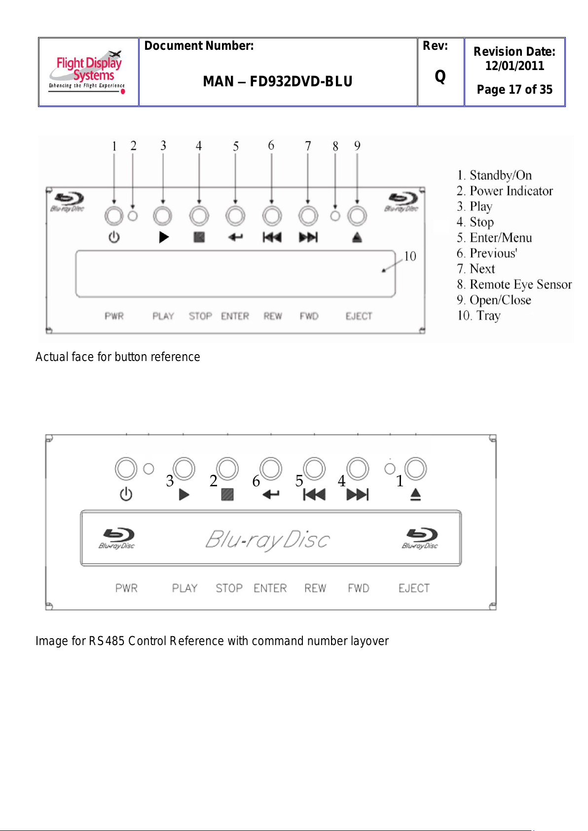
Note: The images on the next two pages are only for reference when programming RS485 controls.
The first picture on each page is the actual face used for reference. The second image on each page
is for RS485 COMMAND REFERENCE ONLY. The second image contains a text layover of the
actual RS485 command. To determine the RS485 command for Play, look at the first image to
determine the play button, and then look at the second image to determine the command for the
corresponding button. Example: !BR04<CR> will send a command to all Blu-ray players to stop.
Available Commands For Units With Serial Numbers x745, x755, and x757 upon request
Actual face for button reference
All manuals and user guides at all-guides.com
all-guides.com
Document Number:
MAN –FD932DVD-BLU
Rev:
Q
Revision Date:
12/01/2011
Page 17 of 35
Actual face for button reference
Image for RS485 Control Reference with command number layover
1
2
3
4
5
6
All manuals and user guides at all-guides.com

Document Number:
MAN – FD932DVD-BLU
Rev:
Q
Revision Date:
12/01/2011
Page 18 of 35
Available Commands For Units With Serial Number x10629 or x761 and Greater
Actual remote for button reference Image for RS485 Control Reference
with command number layover
All manuals and user guides at all-guides.com

Document Number:
MAN – FD932DVD-BLU
Rev:
Q
Revision Date:
12/01/2011
Page 19 of 35
RS485 Commands Cont’d
PA Commands:
“PA ON” will enable PA interrupt.
“PA OFF” will disable PA interrupt.
NOTE: “PA ON” command must be received every 9 seconds or interrupt will time out.
Addresses:
Up to 7 Blu-ray players can easily exist on the same CAN bus. Each unit must have a unique
address assigned to it in the range 1 through 7 to permit the commands issued from the
remote controllers to be received by the correct units. Use the chart below for information on
setting the address of each Blu-ray player. If there is a dot in the pin column of the chart then
connect that pin to Pin 22. Up to three address pins may be connected to Pin 22 at the same
time.
Examples:
If there is a single Blu-ray player in a system, then it should be set to address 1. The player will
be referenced in all Flight Display Configuration Documents as Blu-ray Player #1 or “The Blu-
ray Player.”
If there are two Blu-ray players in a system, then one should be set to address 1 and the other
should be set to address 2. The player that is set to address 1 will be referenced in all Flight
Display Configuration Documents as Blu-ray Player #1. The other Blu-ray Player will be
referenced as Blu-ray Player #2.
If there are three Blu-ray Players, then the Blu-ray player referenced as Blu-ray #1 in the Flight
Display Configuration Documents should be set to address 1, the Blu-ray player referenced as
Blu-ray #2 should be set to address 2, and the Blu-ray player referenced as Blu-ray #3 should
be set to address 3.
This addressing system is used for all installations containing from one to seven players.
= connect to ground (Pin 22)
Address
Pin 23
Pin 24
Pin 25
1
2
3
4
5
6
7
All manuals and user guides at all-guides.com

Document Number:
MAN – FD932DVD-BLU
Rev:
Q
Revision Date:
12/01/2011
Page 20 of 35
Infrared Control
The FD932DVD-BLU & FD932DVD-BLU Ver CV has the ability to use an infrared external eye,
which is supplied by Flight Display Systems. The following guidelines should be met when
using the external IR eye to insure correct and optimal operation.
IR Data, IR Ground, and IR 5V pins on DB25 connector listed above are intended
for use by supplied 12‟ IR remote receiver only.
IR Data line can be used on open-collector style IR receivers. The line needs to be
in a Tri-state condition while not in use.
Contact Flight Display Systems before installing different IR control schemes
All manuals and user guides at all-guides.com
This manual suits for next models
1
Table of contents
Other Flight Display Systems DVD Player manuals

Flight Display Systems
Flight Display Systems FD932DVD-LP-2 User manual

Flight Display Systems
Flight Display Systems FD932DVD-LP-2-4B User manual

Flight Display Systems
Flight Display Systems FD932DVD-4B User manual

Flight Display Systems
Flight Display Systems FD932DVD-LP-2-AV User manual

Flight Display Systems
Flight Display Systems FD932DVD-LP Owner's manual


