manuals.online logo
Brands
  1. Home
  2. •
  3. Brands
  4. •
  5. Flight Model
  6. •
  7. Toy
  8. •
  9. Flight Model Courage-8 40 Instructions for use

Flight Model Courage-8 40 Instructions for use

SPECIFICATION:
Wing󴖦span:57in/1448mm
Wing󴖦area:36.1sq.dm
Length:44.3in/1125mm
Flying󴖦weight:2100-2350g
Engine:2cycle󴖦40-46
Radio:4channels󴖦4servos
CONSTRUCTION GUIDE
1 Epoxy the 2 identical plywood wing joiners together.
Cut out aileron servo opening on top of wing panels.
2 Looking forward towards the leading edge, the wing should form a "V" when assembled.
The top of the wing has lettering on it.
3
4Install the main landing gears as shown. Attach with the screws that you should have purchased
(No. 2 by 1/2")
Next, glue the hardwood torque rod covers in place. They have a notch in them to allow for
movement of the aileron rod. You may have to enlarge the holea little to allow for proper
movement.
The wing is joined together by inserting one plywood dihedral braces into each wing panel and
then epoxying into place.You may want to check the fit first, before gluing. Make sure that the
wing panels butt together closely so that the dihedral angle is correct. Before gluing, you can
cut into the wing panels a hole large enough to accommodate the plywood servo mount.This mount is
2*3/8" by 1*9/16" and fits onto the dihedral brace, it is supported by two pieces of plywood
1*1/16" by 1*1/16" one which should be glued to the dihedral brace after the wing is joined
together.(It protrudes through the top on the low wing versions.) Apply a liberal amount of epoxy
to the brace and to the wing panels when joining together, wipe off any excess, and then tape the
panels together to insure a good glue joint. Once together, glue in the servo mount. A piece of
clear plastic tape is wraped around the center section of the wing to seal the glue joint.
5
6Assembly the fuel tank as shown. Apply a bead of silicone sealant around the fuel tank cap as
shown when installing it into the fuselage.
Hook up noes wheel steering pushrod and route through housing which is installed into servo area.
The nose gear is incorporated into the engine mount. The steering cable is routed along the left
side of the fuselage and attached to rudder servo.Check the diagram for assembly.
7Offset the engine by two degrees to the right. Drill four 7/64" holes for the engine. Use the
selftapping screws supplied. Install the nose wheel assembly at this time.
8The elevator must be attached to horizontal stabilizer using 3 hinges. You may have to trim the
elevator to fit the stabilizer. The stabilizer should be flush with rear of the fuselage as per
the diagram.
IT IS ESSENTIAL THAT THE STABILIZER AND THE RUDDER ARE 90 DEGREES TO EACH OTHER, AND THAT THE
WING 15 PARALLEL TO THE STABILIZER.
A good way to check the alignment is to first attach the wing to the fuselage. Slide the
stabilizer into the fuselage, making sure that it is centered. Place the airplane on a table or
some steady surface and then stand back. Look at the airplane from the front, the engine would be
the closest thing to you. Stand back about 8 feet and try to have your sight level with the
engine. It will be immediately apparent if the wing is not parallel with the stabilizer.
Trim the fuselage to fit the stabilizer properly. Fill any gap with scrap wood or epoxy.
Glue vertical stabilizer into the fuselage and onto the stabilizer. The rudder attaches to the
vertical stabilizer with two hinges.
9
The wing is mounted to the fuselage by using (80)#64 rubber bands.
The bands are designed to pop off during hard langings and thus help prevent major
damage.Four rubber bands are needed per side.
Two wooden dowels are inserted through the fuselage to hold the wing in place. No.62
rubber bands are used to attach the wing.At least 4 rubber bands should be used on each
side.
Wrap the bands around the wooden dowels as shown above.This design is to allow for those
not-so-perfect landings that come with learning how to fly.
At this time be certain that the aileton servo is connected to the receiver,otherwise the
wing will need to be removed later to connect it.
10
The pushrods are made of wood and are to be assembled as shown in the drawing.
Attach the rod to the servos with a anap keeper, the same as the aileron pushrods. The
throttle pushrod is just a length of 3/64" wire sliding in the preinstalled tube. Be sure
to adjust it so that you have full movement of the carburetor without stalling the servo.
Check the size of the servo holes in the fuselage servo tray; alter as necessary. epoxy
into the fuse, and install the servos. Tutn on the system and check the operation of the
servos; they shuold all work without interfering with each other or the fuse.
Attach the rod to the horn, set the surface and the servo to neutral, and mark the length
on the ftont rod. Remove the rod, make a rightangle bendin the wire, and cut off the
escess.
The bent rods included are for the servo ends and the threaded todsare for the back ends.
After mounting the control horns on the rudder and elevator (use the squares of clear
plastic between the horn and the surface, and between the nut plate and the surface) you
11 The canopy is installed as shown using epoxy glue.
12 The amount of the travel needed for the variour control surfaces is shown.

Other Flight Model Toy manuals

Flight Model Extra 330SC 100CC User manual
Flight Model

Flight Model Extra 330SC 100CC User manual

Flight Model F0081 Katana 26-30CC Operation instructions
Flight Model

Flight Model F0081 Katana 26-30CC Operation instructions

Flight Model Kelly F1 60 Operation instructions
Flight Model

Flight Model Kelly F1 60 Operation instructions

Flight Model F126 PITTS S12 94.5" Operation instructions
Flight Model

Flight Model F126 PITTS S12 94.5" Operation instructions

Flight Model ME-110 Operation instructions
Flight Model

Flight Model ME-110 Operation instructions

Flight Model F124 MXS-R 30-35CC User manual
Flight Model

Flight Model F124 MXS-R 30-35CC User manual

Flight Model F080 Zero Flighter 91" User manual
Flight Model

Flight Model F080 Zero Flighter 91" User manual

Flight Model Taylorcraft-90 Operation instructions

Flight Model

Flight Model Taylorcraft-90 Operation instructions

Flight Model ZERO A6M5B User manual

Flight Model

Flight Model ZERO A6M5B User manual

Flight Model P-51 Mustang User manual
Flight Model

Flight Model P-51 Mustang User manual

Flight Model YAK-54 35-40CC Operation instructions
Flight Model

Flight Model YAK-54 35-40CC Operation instructions

Flight Model F168 PZL-104 WILGA User manual
Flight Model

Flight Model F168 PZL-104 WILGA User manual

Flight Model SU-31 Operation instructions
Flight Model

Flight Model SU-31 Operation instructions

Flight Model M067 Slick 70" EP User manual
Flight Model

Flight Model M067 Slick 70" EP User manual

Flight Model F114 Sbach 342 20cc User manual
Flight Model

Flight Model F114 Sbach 342 20cc User manual

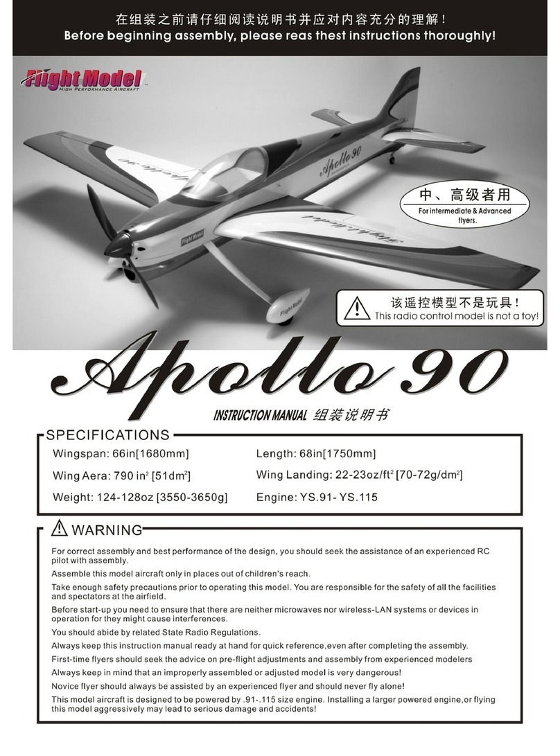
Flight Model Apollo 90 User manual

Flight Model

Flight Model Apollo 90 User manual
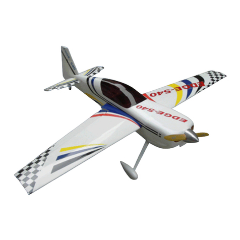
Flight Model EDGE-540 50CC User manual
Flight Model

Flight Model EDGE-540 50CC User manual

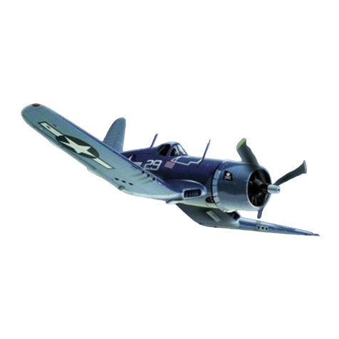
Flight Model F-4U Corsair 100CC Operation instructions
Flight Model

Flight Model F-4U Corsair 100CC Operation instructions

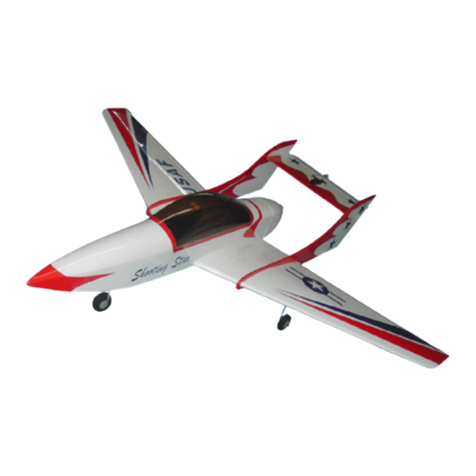
Flight Model Shooting Star Operation instructions
Flight Model

Flight Model Shooting Star Operation instructions

Flight Model Extra-330 30-35CC Operation instructions

Flight Model

Flight Model Extra-330 30-35CC Operation instructions

Flight Model F113 YAK 54 20CC profile User manual

Flight Model

Flight Model F113 YAK 54 20CC profile User manual

Flight Model F070 Stick-46 User manual

Flight Model

Flight Model F070 Stick-46 User manual

Flight Model Monsun-60 Operation instructions

Flight Model

Flight Model Monsun-60 Operation instructions

Flight Model F136 SU-29 26-30CC Operation instructions

Flight Model

Flight Model F136 SU-29 26-30CC Operation instructions

Popular Toy manuals by other brands
Eduard OV-1A/B/D wheel well /undercarriage manual

Eduard

Eduard OV-1A/B/D wheel well /undercarriage manual

Bandai Evatchi instruction manual

Bandai

Bandai Evatchi instruction manual

Tomahawk Monsun 20700 instruction manual

Tomahawk

Tomahawk Monsun 20700 instruction manual

Phoenix Model Spitfire instruction manual

Phoenix Model

Phoenix Model Spitfire instruction manual

Sol-Expert eMaxchen instructions

Sol-Expert

Sol-Expert eMaxchen instructions

M.T.H. HO Crossing Gate manual

M.T.H.

M.T.H. HO Crossing Gate manual

Durafly Retro Series Junior models Plug and Fly instruction manual

Durafly

Durafly Retro Series Junior models Plug and Fly instruction manual

ZAZU Felix the fox manual

ZAZU

ZAZU Felix the fox manual
SYMA S107H-E user manual

SYMA

SYMA S107H-E user manual

Accessible Technologies PROCHARGER 2014+ C7 Corvette installation guide

Accessible Technologies

Accessible Technologies PROCHARGER 2014+ C7 Corvette installation guide

Fisher-Price Talking Chef Magic Kitchen 74839 manual
Fisher-Price

Fisher-Price Talking Chef Magic Kitchen 74839 manual

Flyzone nieport 17 instruction manual

Flyzone

Flyzone nieport 17 instruction manual

REVELL KIT 5715 Assembly manual

REVELL

REVELL KIT 5715 Assembly manual

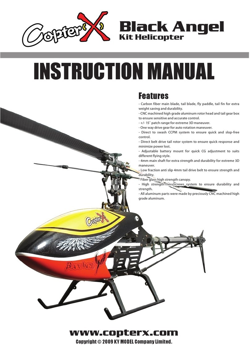
CopterX Black Angel instruction manual
CopterX

CopterX Black Angel instruction manual
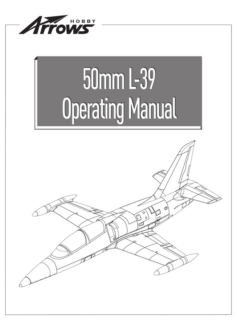
Arrows Hobby 50mm L-39 operating manual

Arrows Hobby

Arrows Hobby 50mm L-39 operating manual

Hasbro Marvel Iron Man Repulsor Power manual

Hasbro

Hasbro Marvel Iron Man Repulsor Power manual

Brookstone Rover quick start guide

Brookstone

Brookstone Rover quick start guide

Little Tikes TREASURE TROVE WATER TABLE manual

Little Tikes

Little Tikes TREASURE TROVE WATER TABLE manual

manuals.online logo
manuals.online logoBrands
  • About & Mission
  • Contact us
  • Privacy Policy
  • Terms and Conditions

Copyright 2025 Manuals.Online. All Rights Reserved.