FLIR PTZ-35x140MS User manual

427-0011-00-10 Revision 140 Copyright © FLIR Systems, Inc. 1
P
PT
TZ
Z-
-3
35
5x
x1
14
40
0M
MS
S
S
SR
R-
-3
35
5x
x1
14
40
0M
MS
S
I
In
ns
st
ta
al
ll
la
at
ti
io
on
n
a
an
nd
d
O
Op
pe
er
ra
at
ti
io
on
n
M
Ma
an
nu
ua
al
l
FLIR Systems, Inc. Aug 2011
70 Castilian Drive
Goleta, CA 93117
Phone: 888.747.FLIR (888.747.3547)
International: +1.805.964.9797 http:// www.flir.com
ThisdocumentiscontrolledtoFLIRTechnologyLevel1.Theinformationcontainedinthisdocument
pertainstoadualuseproductcontrolledforexportbytheExportAdministrationRegulations(EAR).FLIR
tradesecretscontainedhereinaresubjecttodisclosurerestrictionsasamatteroflaw.Diversioncontrary
toUSlawisprohibited.USDepartmentofCommerceauthorizationisnotrequiredpriortoexportor
transfertoforeignpersonsorpartiesunlessotherwiseprohibited.

427-0011-00-10 Revision 140 Copyright © FLIR Systems, Inc. 2
FLIR Systems Inc.
70 Castilian Dr.
Goleta, CA 93117-3027
888.747.FLIR (888.747.3547)
Intl.: +1.805.964.9797
FAX 805 685-2711
www.flir.com
Document Number: 427-0011-00-10
Revision Number: 140
Date: August 2011
EXPORT RESTRICTIONS
The information contained in this document may be controlled for export purposes by the United States
Government. Diversion contrary to US law is prohibited. For more information, contact FLIR Systems, Inc.
This document and data disclosed herein or herewith is not to be reproduced, used, or disclosed in whole
or in part to anyone without the permission of FLIR Systems, Inc.
PROPRIETARY
The data in this publication shall not be disclosed without permission and shall not be duplicated, used, or
disclosed in whole or in part except to the extent provided in any contract of which this document is made
a part. This restriction does not limit the customer’s right to use information contained in this document if it
is obtainable from another source without restriction. The data subject to this restriction are contained in
all sheets of this document and related drawings and document specifications herein. FLIR reserves the
right to make changes to its products or specifications at any time, without notice, in order to improve
design or performance and to supply the best possible product.
COPYRIGHT
Copyright © 2011 FLIR Systems, Inc. All rights reserved. This publication, or any parts thereof, may not
be reproduced in any form without the express written permission of FLIR Systems, Inc.
FEDERAL COMMUNICATIONS COMMISSION REGULATORY INFORMATION
Modification of this device without the express authorization of FLIR Commercial Systems, Inc., may void
the user’s authority under the FCC Rules to operate this device.
Note: This equipment has been tested and found to comply with the limits for a Class A digital device,
pursuant to part 15 of the FCC Rules. These limits are designed to provide reasonable protection against
harmful interference when the equipment is operated in a commercial environment. This equipment
generates, uses, and can radiate radio frequency energy and, if not installed and used in accordance with
the instruction manual, may cause harmful interference to radio communications. Operation of this
equipment in a residential area is likely to cause harmful interference in which case the user will be
required to correct the interference at the user’s expense.
Shielded cables must be used to connect this device to other devices.
Warning – This is a Class A product. In a domestic environment this product may cause radio
interference in which case the user may be required to take adequate measures.
Pelco is a registered trademark of Pelco. Windows is a registered trademark of Microsoft Corporation.

427-0011-00-10 Revision 140 Copyright © FLIR Systems, Inc. 3
TABLE OF CONTENTS
1.0WARNINGS AND CAUTIONS ...................................................................... 5
2.0INTRODUCTION........................................................................................... 6
2.1Advantages of Thermal Imaging......................................................................... 8
2.2Camera Enclosures ............................................................................................ 9
2.3Camera Control .................................................................................................. 9
2.4Package Contents ............................................................................................ 10
3.0INSTALLATION .......................................................................................... 11
3.1Installation Overview ........................................................................................ 11
3.2Camera Mounting ............................................................................................. 12
3.3Camera Connections........................................................................................ 13
3.4Software Installation ......................................................................................... 15
3.5Configuration and Control................................................................................. 15
4.0VERIFY CAMERA OPERATION................................................................. 16
4.1Bench Test Using FLIR Sensors Manager (FSM) ............................................ 17
5.0CAMERA CONFIGURATION...................................................................... 21
5.1Web Configuration Overview............................................................................ 21
5.2Serial Communications..................................................................................... 27
5.3Configuration File ............................................................................................. 28
6.0CAMERA OPERATION............................................................................... 29
6.1Thermal Imaging............................................................................................... 29
6.2Flat Field Correction (FFC)............................................................................... 29
6.3Pelco “D” Control .............................................................................................. 29
6.4Pelco “D” Command List .................................................................................. 30
7.0CARING FOR YOUR 35X140MS THERMAL CAMERA............................. 30
7.1Temperature ..................................................................................................... 31
7.2Maintenance ..................................................................................................... 31
7.3Troubleshooting Problems................................................................................ 31
8.035X140MS CAMERA SPECIFICATIONS................................................... 33
8.1Environmental Requirements ........................................................................... 34
8.2PTZ-35x140 PHYSICAL Dimensions ............................................................... 35
8.3System Interface Cable Connector................................................................... 40
9.0DOCUMENT HISTORY............................................................................... 42
10.0USER CONTROLS FOR KBD300A ..................................................... 43

427-0011-00-10 Revision 140 Copyright © FLIR Systems, Inc. 4
TABLE OF FIGURES
Figure 1-1: Thermal imaging allows 24/7 threat detection ............................................................4
Figure 2-1: SR-35x140MS ............................................................................................................6
Figure 2-2: Foveal View (note the inset 5° field-of-view in both pictures ) ....................................7
Figure 2-3 : Daylight camera on left; Thermal image on right.......................................................8
Figure 2-4: Backlit daylight camera on left; thermal image on right ..............................................9
Figure 2-5: White Hot palette on left, Black Hot palette on right .................................................10
Figure 7-1: PTZ-35x140MS Dimension Drawing (inches) ..........................................................36
Figure 8-1: SR-35x140MS Dimension Drawing (inches) ............................................................38
Figure 9-1: PTZ/SR-35x140MS Interface Cable Connector .......................................................40
Figure 9-2: Break-Out Connector Cable .....................................................................................41
Figure 1-1: Thermal imaging allows 24/7 threat detection

427-0011-00-10 Revision 140 Copyright © FLIR Systems, Inc. 5
1.0 WARNINGS AND CAUTIONS
Caution! This guide uses the term Caution! to indicate a potentially hazardous situation, which,
if not avoided, may result in bodily harm or injury, damage to the camera, or other property
damage.
Protect Your Investment
Do not disassemble the camera enclosure. Disassembly can cause permanent damage and
will void the warranty.
The camera should be installed by a trained professional according to local codes and industry-
standard safe practices.
Proper ESD protocol should be followed while working inside the unit.
The camera is a precision optical instrument and should not be exposed to excessive shock or
vibration.
When not in use, put the camera in the Park position to protect the lenses. It is a good idea to
avoid pointing the system directly at extremely high-intensity radiation sources, such as the sun,
lasers, arc welders, etc. This warning applies whether or not the system is powered.
Great care should be used with your camera’s optics. They are delicate and can be damaged by
improper cleaning. Only clean the lens in the manner described in section 7.0 Caring for your
35x140MS Thermal Camera.
Legal Considerations
Camera and audio surveillance may be prohibited by laws that vary from country to country.
Check the laws in your local region before using this product for surveillance purposes.
Support
If you have questions that are not covered in this manual, or need service, contact FLIR
Customer Support at (805) 964-9797 for additional information prior to returning your 35x140MS
Thermal Camera. In the US, you can also reach FLIR Customer Support at (888) 747-FLIR
(747-3547).
All thermal imaging systems are subject to export control. Please contact FLIR for export
compliance information concerning your application or geographic area.
This equipment must be disposed of as electronic waste.
Contact your nearest FLIR Commercial Vision Systems, Inc. representative for instructions
on how to return the product to FLIR for proper disposal.

427-0011-00-10 Revision 140 Copyright © FLIR Systems, Inc. 6
2.0 INTRODUCTION
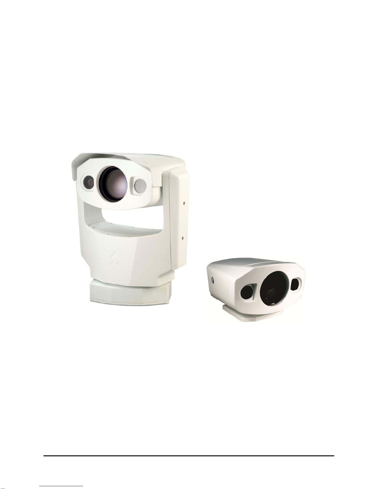
The PTZ-35x140MS and SR-35x140MS are high-resolution multi-sensor (MS) camera systems
designed specifically for the security market for medium- to long-range security applications.
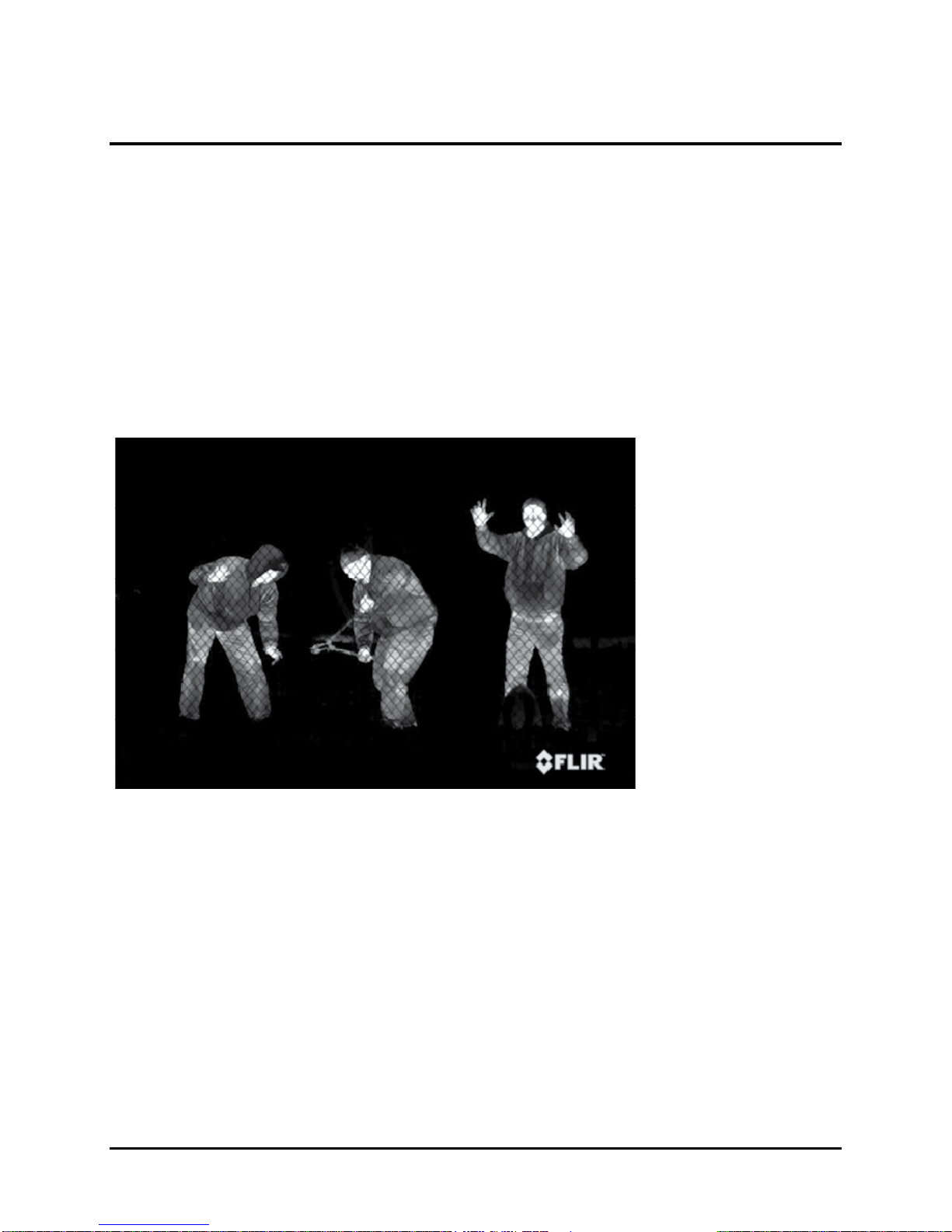
Each model includes a sophisticated thermal imaging system that provides excellent night
visibility and situational awareness, even in absolute darkness, as well as a standard high
resolution low-light video camera1, integrated into a compact weather enclosure.
Each system includes a versatile, dual field-of-view thermal imaging system called Foveus, a
FLIR-patented innovation, which provides a high-resolution thermal image with a 5° view nested
inside a wider 20° view. This image presentation concept, derived from the same principles as
human vision, offers excellent situational awareness and long range threat detection,
simultaneously. Each system has two thermal imagers: a 35mm camera for wide-angle
surveillance, and a long-range 140mm camera, and the ability to continuously zoom between
the two fields of view.
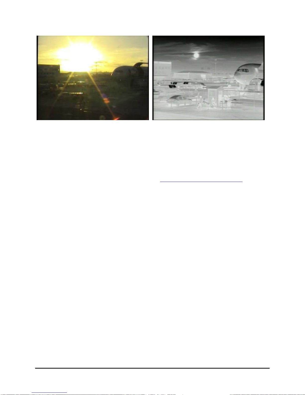
This thermal imaging system is complimented with a high-resolution daylight camera, providing
optimal surveillance regardless of the time of day or lighting conditions. With the touch of a
button you can switch between the thermal imager and the daylight / low light camera. The
daylight camera provides up to 26x optical zoom. Displaying both the thermal image and the
daylight image at the same time is also possible via Ethernet.
Figure 2-1: SR-35x140MS
The SR-35x140MS is used for fixed-mount applications, or it can be integrated with a pan/tilt
mechanism. The camera provides crisp, clear thermal imagery in total darkness, light fog or
smoke. On the PTZ-35x140MS, this advanced payload is packaged in a precision pan/tilt
enclosure that will slew up to 120° per second. Each system provides standard video output
(PAL or NTSC format) that works with digital video recording devices, video motion detection
software or off-the-shelf video encoders.
Both 35x140MS camera systems have the performance of military-grade camera systems at a
fraction of the cost. Security operators can field them as portable stand-alone cameras, or
integrate them into a camera network. The cameras provide serial and analog connectivity for
existing legacy infrastructures using widely-deployed interface standards. Either system can be
integrated into IP Video security infrastructures using TCP/IP standards. The cameras support
network operation and control through the Nexus ™ architecture using FLIR Sensors Manager
(FSM) software or a third-party VMS. Video can be streamed over TCP/IP using FSM or a third
party video player.
1The standard video camera is referred to in this manual generally as a daylight camera or
DLTV.
Daylight
camera
140mm lens
35mm lens

427-0011-00-10 Revision 140 Copyright © FLIR Systems, Inc. 7
The Foveal Concept
The PTZ-35x140MS and SR-35x140MS feature a completely new concept in image
presentation based on the foveal vision of the human eye. Foveal vision allows the operator to
enjoy a wide angle view for situational awareness while maintaining a high resolution area in the
center of the screen for object identification and tracking.
The PTZ-35x140MS and SR-35x140MS accomplish this with two independent thermal cameras
and a unique patented image processing technique that provides both the foveal imaging mode
as well as a continuous zoom between the wide and narrow fields of view.
The Foveus thermal imagery is provided as continually zoomed video from the wide 20°
horizontal field-of-view (from the 35mm lens) to the more narrow 5° field-of-view (from the
140mm lens). The thermal imagery is presented by blending the two thermal images to provide
high visual acuity in the critical 5° center area while simultaneously providing medium resolution
in the 20° situational awareness zone. This presentation is an application of the design of the
human eye, with the foveal region of the retina employing higher sensitivity than the peripheral
area, thus the moniker Foveus™.
When the system is zoomed out, the video output comes from the 20° field-of-view and the 5°
field-of-view disappears. After zooming in slightly, the wide 5° field-of-view appears as a small
inset window in the center. Continuing to zoom in causes the inset window to grow until it fills
the video screen, eliminating the wide field-of-view.
Figure 2-2: Foveal View (note the inset 5° field-of-view in both pictures)
The image on the left shows the wide overall perspective of the 20° field-of-view, and the
camera is partially zoomed in to show with the narrower field-of-view. The image on the right
shows the camera nearly fully zoomed in, and the 5° field-of-view dominates the image.
The 5° horizontal field-of-view of the 140mm lens provides long range surveillance with high
visual acuity of distant targets. The 35mm lens provides a short to medium field-of-view of 20°
and is well-suited for short range threat detection in all circumstances. The wide field-of-view
allows it to cover a large area and provide excellent situational awareness. And the patented
technology of FLIR allows continuous zoom between both fields of view.

427-0011-00-10 Revision 140 Copyright © FLIR Systems, Inc. 8
2.1 Advantages of Thermal Imaging
The 35x140MS camera is designed for simple, intuitive installation and operation. Each thermal
camera is based on FLIR’s widely-deployed uncooled microbolometer imaging core. All
cameras include FLIR’s advanced image processing techniques which deliver excellent contrast
regardless of scene dynamics. Unlike other night vision systems that require low amounts of
light to generate an image, the 35x140MS thermal imagers need no light at all.
The 35x140MS can be easily integrated with current systems employing daylight cameras. Initial
setup of the system includes connecting power supply leads for the input power and BNC cable
for monitoring output video (one cable is used for both the thermal and daylight video). A serial
cable can be connected to allow control of the camera (pan, tilt, zoom, focus, and so on) and
modify camera settings, and an Ethernet port is available for integration into IP networks.
FLIR’s powerful thermal security cameras compliment and complete your security camera
network. They turn night into day, allowing you to see intruders invisible to the naked eye.
Thermal cameras create video images from infrared thermal energy (heat), and perform well at
night and day, in good weather and bad.
Figure 2-3 : Daylight camera on left; Thermal image on right
Under some environmental conditions, such as haze, or certain lighting conditions, such as
scenes with shadows, you will likely find that the thermal camera may outperform the daylight
camera, even during the day. Observe that the image above on the left from an ordinary
daylight camera is obscured by fog, while the thermal image on the right provides clear details.
Originally developed for the military, thermal imaging cameras are now deployed in numerous
commercial applications where it is impractical or too expensive to use active illumination
(lights). It is perfect for wide-area surveillance in critical infrastructure or high-value residence
installations where lighting is unwelcome or impractical. The camera also provides improved
daytime surveillance in environments where traditional CCTV security camera performance
suffers, such as in shadows, backlit scenes or through foliage.

427-0011-00-10 Revision 140 Copyright © FLIR Systems, Inc. 9
Figure 2-4: Backlit daylight camera on left; thermal image on right
Observe that the setting sun in the backlit image on the left makes it difficult to discern any
objects of interest; the thermal image on the right is not affected by the bright sun and therefore
provides detail and contrast.
2.2 Camera Enclosures
The PTZ-35x140MS and SR-35x140MS cameras are packaged in environmental enclosures
that meet IPX6 test standards. Refer to section 8.0 35x140MS Camera Specifications for
additional specifications. The camera’s sun shroud around the enclosure helps regulate the
camera temperature in direct-sun installations. Each camera uses a lens heater to provide
sharp imagery in all temperature and weather conditions, ensuring a clear lens and high-quality
infrared video, even in extremely cold environments.
2.3 Camera Control
The 35x140MS cameras have serial communication leads for control of the camera utilizing RS-
422 protocol. Users can control the camera using devices that support the Pelco® “D” protocol.
The serial control is connected with a standard 9-pin connector (DB9) via the provided System
Cable.
The camera can also be attached to an IP network through the Ethernet interface and controlled
through the supplied FLIR Sensors Manager software running on your PC. The software allows
streaming video and allows multiple users to control and/or monitor the camera.
Either method for remote control can be used to operate the following functions or features:
Pan/Tilt (PTZ-35x140MS only) and Zoom
Camera focus
Toggle analog video output between the thermal camera and the daylight camera
Selectable Automatic Gain Control (AGC) and Dynamic Detail Enhancement (DDE)
settings for optimization of video imagery
Camera Palette (also known as Polarity) - by default the White Hot palette is used;
alternatively the Black Hot palette displays warmer objects as black or dark rather than
white or light shades. Additional pseudo color palettes are available using the application
software supplied with the camera.
Other controls specific to the thermal imager (refer to section 6.0 Camera Operation for
additional details on controlling the camera

427-0011-00-10 Revision 140 Copyright © FLIR Systems, Inc. 10
Figure 2-5: White Hot palette on left, Black Hot palette on right
2.4 Package Contents
Refer to the Shipping Check List that is shipped with each camera for a description of the parts
and components that are included with the camera. If there is any discrepancy between the list
and the contents of your shipment, please contact FLIR Systems Customer Support
immediately using the contact information at the front of this manual.
For a list of optional accessories, refer to the FLIR web site: http://www.flir.com/.

427-0011-00-10 Revision 140 Copyright © FLIR Systems, Inc. 11
3.0 INSTALLATION
General installation information for both 35x140MS cameras is given below. If you have a
question regarding installation or operation of your 35x140MS camera, contact FLIR Systems,
Inc Customer Support, using the contact information at the front of this manual. Check out our
training web site (http://www.flir.com/training/) to get information on courses offered and to learn
how you can become a FLIR-authorized Installer.
Caution! Be careful during the installation process so the lenses do not get damaged or dirty.
Do not forget to remove the protective adhesive sheet after the installation is complete.
Caution! Proper ESD protocol should be followed while working with the unit.
3.1 Installation Overview
Disassembly of the camera is not required for installation. Disassembling the camera can cause
permanent damage and will void the warranty.
In most installations, the camera will be connected via a System Cable (P/N 308-0116-02) and a
Break-Out Connector Cable (P/N 308-0117-00). The breakout cable provides the following
connections (labels given in parentheses):
BNC for composite video (VIDEO P2)
RJ45 Ethernet (ETHERNET P5)
System power with 2 terminal rings (SYS PWR)
Pan/Tilt power with 2 terminal rings (PT PWR)
DB9 RS-422 for serial communications (USER
P3)
DB9 Maintenance connection, used for service
only (Maintenance P4), with termination plug
(termination plug is required)
Each breakout end of the cable (away from the
camera) must be protected from the weather.
Important!
When the Break-Out Connector Cable is used with the optional 40 ft System Cable,
connect the Ethernet to a switch or router using a twisted pair cable that does not exceed 2
meters.

427-0011-00-10 Revision 140 Copyright © FLIR Systems, Inc. 12
Optional Accessories
For installation purposes, the following optional accessories are available.
40 ft System Cable 308-0116-02
24VAC Power Supply 206-0004-01
Joystick 223-0017-00
3.2 Camera Mounting
Firmly secure the camera to a designated frame or structure capable of supporting the camera,
using the mounting pattern shown below. For the PTZ-35x140MS, be sure to allow for device
travel by providing a clearance cylinder of 15.5” (39.37cm) diameter and 22” (55.88cm) height.
Mounting the SR-35x140MS camera is accomplished using the six 1/4-20 tripod mount holes or
the single 3/8-16 central mount hole on the underside of the enclosure foot. The dimensions of
the camera mounting foot are provided in section 8.0 35x140MS Camera Specifications for
reference.
The SR-35x140MS enclosure can be mounted to a wall mount, ceiling or pedestal mount, or a
pan/tilt mechanism on a wall or ceiling. Refer to the manufacturer’s documentation
accompanying the fixed or pan/tilt mount for more information regarding installation and
mounting.

427-0011-00-10 Revision 140 Copyright © FLIR Systems, Inc. 13
3.3 Camera Connections
Connect the sealed System Cable to the connection on the camera base shown above. Then
attach the other end of the System Cable to the Break-Out Connector Cable. The far end of the
breakout cable must be protected from the weather.
Ground Connection
The 35x140MS cameras have grounding and surge protection to provide limited immunity from
high current transients that can occur in installations subject to electrical storms and/or nearby
lightning events. In order to ensure CE and FCC compliance as well as to protect against
these high current events, installers are required to provide an Earth connection to a specific
connection on the camera (the ground lug indicated above). Note: a ground connection to the
exterior of the camera (for example, to the mounting foot) is insufficient.
Caution! The camera must be installed according to industry-standard practices and local
electrical codes. Failure to properly connect the enclosure and the electrical interface board to
ground could result in damage to the camera and possible bodily injury.
Input Power
The 35x140MS cameras operate on 24Volts (nominal) power, AC or DC. The camera has
separate power connections for the pan/tilt mechanism and the rest of the system. Provide
either 24+/-10% VAC rms (50/60Hz) or 24+/-10% VDC directly to the connections labeled
“PTPWR” and “SYSPWR” on the break-out cable.

427-0011-00-10 Revision 140 Copyright © FLIR Systems, Inc. 14
Optional Power Supply
The connections labeled “PTPWR” and “SYSPWR” on the break-out cable can be directly
connected to the optional power supply. Connect the black leads to COM and the red leads to
24V. Next, adjust the AC Input switch to either 115VAC (standard for US) or 230VAC (standard
for Europe) and apply power to the power supply.
Fuse Protection
The optional power supply system is fuse-protected against over-voltage conditions. A blown
fuse is an indication either that the circuit has been overloaded or that a short circuit has
occurred somewhere in the circuit. A wiring problem may be placing too much of a load on the
circuit if a fuse blows after plugging in or turning on the camera. Before replacing the fuse it is
important to identify what has caused it to fail.
Prior to changing a fuse, turn off the electrical circuit or completely disconnect the camera.
Make certain that no dangerous condition exists before restoring power. Replace the fuse with a
fuse that is of the same rating and proper for the circuit. Never use anything other than a fuse of
proper rating.
Caution! Failure to disconnect power to the camera while replacing a fuse could result in
accidental injury or death.
Analog Video Output
For analog video output, plug a standard BNC cable to the connection labeled “VIDEO P2” on
the break-out cable.
The analog video signal is accessed via a standard coaxial cable BNC connector and meets the
requirements of NTSC or PAL video standards, depending on the configuration ordered. The
analog video signal is intended to drive video coaxial cable and is designed to transmit a 75
ohm load with minimum signal loss. Excessive signal loss and reflection occurs if cable rated for
other than 75 ohms is used. Cable characteristics are determined by a number of factors (core
material, dielectric material and shield construction, among others) and must be carefully
matched to the specific application. Moreover, the transmission characteristics of the cable will
be influenced by the physical environment through which the cable is run and the method of
installation.
In video security systems, camera signals must travel from the camera to the monitor. Proper
termination of cables is essential to a system's reliable performance. The end point of any video
cable run must be terminated in 75 ohms. Usually, the cable run will end at the monitor, which
will ensure that this requirement is met.
Ethernet Connection
If you intend to use the FLIR Sensors Manager Software for video streaming and/or remote
control of the device, attach a standard CAT5 cable (not to exceed 2 meters) to the connection
labeled “ETHERNET P5” on the break-out cable. Connect the other end of the cable to a hub,
switch or other Ethernet device.

427-0011-00-10 Revision 140 Copyright © FLIR Systems, Inc. 15
Serial control
If you intend to use the Pelco “D” protocol interface for remote control of the device, attach a
standard DB9 RS-422 cable to the connection labeled “USER P3” on the break-out pigtail.
Connect the other end of the RS-422 cable to an available port on a remote control device such
as a Pelco KBD300A. Note - the pins for receive and transmit signals are relative to the camera
and must be swapped on the controller device. That is, the transmit signals from the camera
must go to the receive pins on the remote control device on the other end, and vice versa. The
connector pin designations are shown below:
3.4 Software Installation
Install the FLIR Sensors Manager (FSM) software on your PC. The software installation
procedure and the PC hardware and software prerequisites are described in the release notes
file provided on the CD.
For detailed information about using FSM, refer to the FSM Users Manual. A .pdf copy of the
manual is installed with the software and can be accessed from the Windows Programs menu
(Start > All Programs > FLIR Sensors Manager).
3.5 Configuration and Control
There are various settings available to the installer/integrator in order to communicate with the
existing equipment and/or to optimize image quality for particular applications. These initial
settings are often typically set at the time of installation and are accessible using a web browser
over the Ethernet interface.
In addition to these initial configuration settings, the cameras have features that are controlled
during ongoing operation in the field at any time, such as electronically controlled focus. These
features can also be controlled through the IP interface and/or through the serial interface.
When both modes of communication (serial and IP) are used, the commands issued over the
serial interface have precedence over the IP commands. For example, if a keyboard/joystick is
connected to the serial interface and a user moves the joystick, the serial interface will take
control of the camera, and if someone is using FSM to operate the camera, that person will
temporarily lose control of the camera. Once the keyboard/joystick is idle and no longer issuing
commands, it will be possible for the FSM user to take control of the camera again. Refer to the
FSM User Manual for more information regarding camera control.
RS-422 DB9 “USER P3”
COM 1 Tx A (-) Signal transmit Pin 2
COM 1 Rx B (+) Signal receive Pin 3
COM GND Pin 4 & 6
COM 1 Tx B (+) Signal transmit Pin 7
COM 1 Rx A (-) Signal receive Pin 8
9 8 7 6
5 4 3 2 1

427-0011-00-10 Revision 140 Copyright © FLIR Systems, Inc. 16
4.0 VERIFY CAMERA OPERATION
Prior to installing the camera in its final location, use a bench test to verify camera operation
and, if necessary, configure the camera for the local network.
Power and analog video
Connect the power to the camera as described above. Connect the video cable from the
camera to a display/monitor. Turn on the camera and verify that video is displayed on the
monitor.
If serial communications is used, connect the serial cable from the camera to a serial device
such as a keyboard, and confirm that the camera is responding to serial commands. Before
using serial communications, it may be necessary to configure the camera serial interface to
operate with the other serial device. For more information, refer to section 5.2 Serial
Communications for more details.
Verify IP Communications
As shipped from the factory, the camera has an IP address of 192.168.250.116 with a netmask
of 255.255.255.0. Configure a laptop or PC with another IP address from this network (for
example, 192.168.250.1). Connect the camera and the laptop to the same Ethernet switch (or
back-to-back with an Ethernet crossover cable).
Open a web browser, enter http://192.168.250.116 in the address bar, and press Enter.
The browser should display the Login screen with an image of a PTZ 35x140MS camera. If the
Login screen appears, then you have established IP communications with the camera.

427-0011-00-10 Revision 140 Copyright © FLIR Systems, Inc. 17
It is not necessary to log in and make changes with the Web Configuration tool right away.
Refer to the following chapter for more information regarding camera configuration. At this time,
it is recommended a bench test of the camera should be performed with the FLIR Sensors
Manager software using the factory configuration and the default IP address.
4.1 Bench Test Using FLIR Sensors Manager (FSM)
The following provides a brief description of how to use FSM to control a camera and stream
video from the camera. For more detailed information on how to use FSM, refer to the FLIR
Sensors Manager User Manual.
If the FSM software has not been installed yet, locate the CD that came with the camera and
install it on the PC.
Running FSM
Run the FSM software by double clicking the icon on the desktop, or click on the
Windows Start button and select Programs > FLIR Sensors Manager 2010 > FLIR
Sensors Manager.

427-0011-00-10 Revision 140 Copyright © FLIR Systems, Inc. 18
Initially the FLIR Sensors Manager splash screen will be displayed. The software version may
be different than the version displayed below.
After a brief while, the FSM main window will appear, and a popup FSM Notification window will
appear in the lower right of the screen indicating that no cameras (servers) have been
discovered yet. Click on the Accept button to acknowledge the notification.
The FLIR Sensors Manager uses a “client/server” architecture. The FSM software is considered
a client, and the cameras are considered servers or sensors. The Sensors Panel indicates no
sensors have been discovered and added to the list of Active Sensors.
Click on the Setup tab along the top of the window to bring up the Discovery Panel. The FSM
software can automatically discover FLIR cameras on the network.

427-0011-00-10 Revision 140 Copyright © FLIR Systems, Inc. 19
Click

427-0011-00-10 Revision 140 Copyright © FLIR Systems, Inc. 20
If necessary, click on the Discovery tab along the right side of the window. When the Discovery
Panel is displayed, click Refresh.
The FLIR camera will appear in the list of Discovered Servers. The asterisk in parenthesis “(*)”
indicates the camera has not been added to the list of Active Servers on the right.
Click on the center bar “>” to move the camera over to the list of Active Servers on the right.
Once the camera has been added to the list of Active Servers, you can click on the Video Wall 0
tab at the top of the screen.
By default, the FSM software will automatically discover sensors in the network, connect to the
first camera it finds, take control of the camera, and display the video from the camera in Video
Wall 0 on the main FSM window.
Select the Video Wall 0 tab and confirm that video is streamed to the
monitor. Confirm it is possible to control the camera using the zoom
controls. For example, click on the zoom button (magnifying glass with
+), and the video will zoom in. Once operation of the camera has been
confirmed, the camera can be configured to an IP address that matches
the installation network.
Once you have verified the basic operation of the camera and successfully streamed video, you
will want to install the camera in its proper location.
Click
Click
This manual suits for next models
1
Table of contents
Other FLIR Security Camera manuals

FLIR
FLIR DPB74TLUX User manual

FLIR
FLIR SR-100 User manual

FLIR
FLIR CB-5222 Manual

FLIR
FLIR CP-6302-30-R User manual

FLIR
FLIR Ariel CM-3202-11-I User manual

FLIR
FLIR DBB13TL-PK4 User manual

FLIR
FLIR MPX C243EW2 Series User manual

FLIR
FLIR MPX C237ED User manual

FLIR
FLIR FXV101-W User manual

FLIR
FLIR DPB24TLX User manual

FLIR
FLIR IP Series User manual

FLIR
FLIR M-Series User manual

FLIR
FLIR SR-124 User manual

FLIR
FLIR Quasar CM-6405 User manual

FLIR
FLIR FX User manual

FLIR
FLIR Ariel Gen II CC-3103 User manual

FLIR
FLIR Digimerge DBV44TL User manual

FLIR
FLIR N347BW4 SERIES User manual

FLIR
FLIR Quasar Gen III Manual

FLIR
FLIR FXV101 User manual