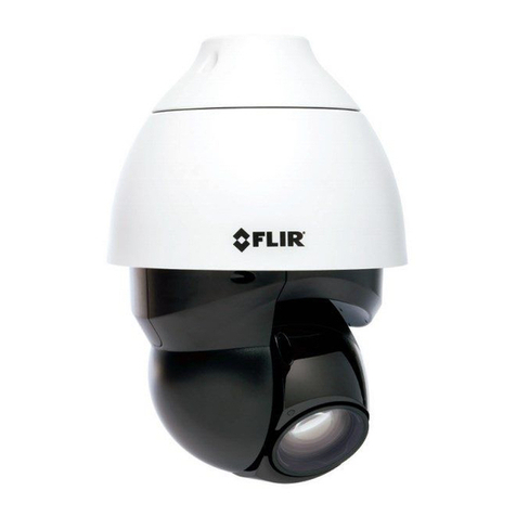
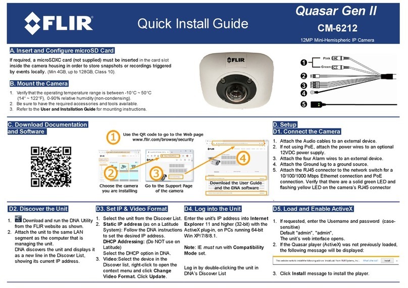
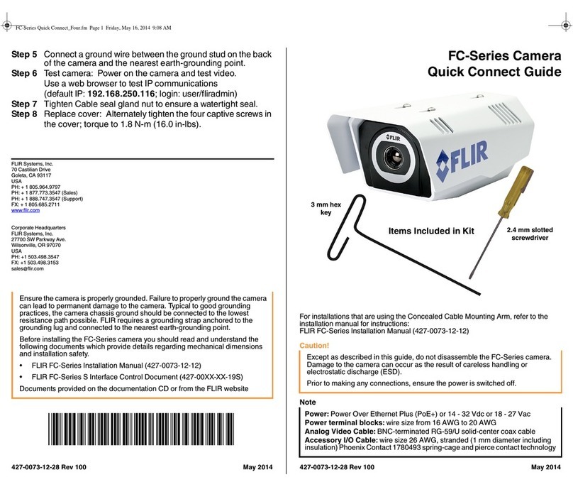
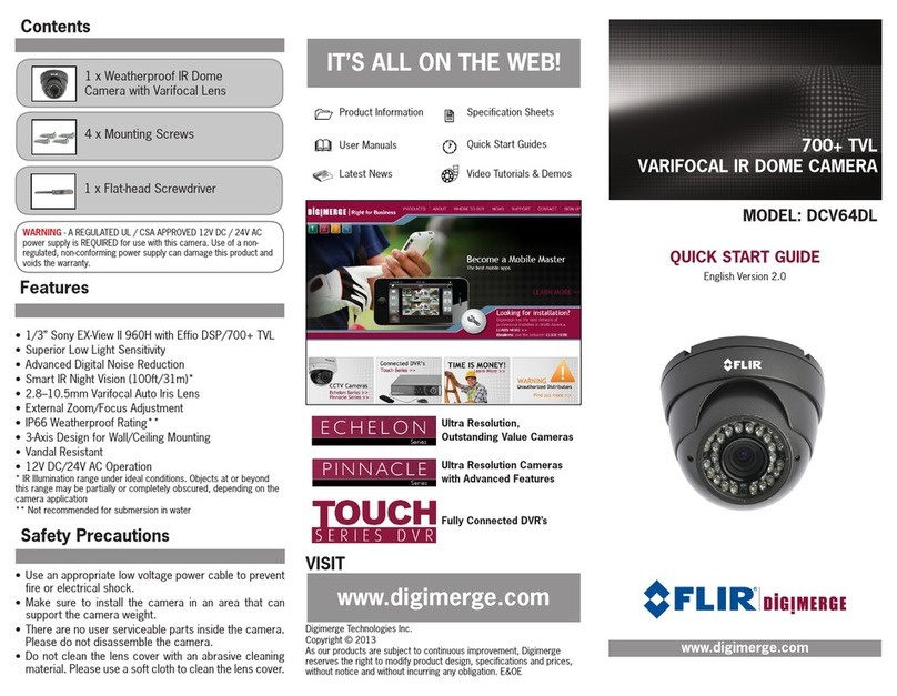
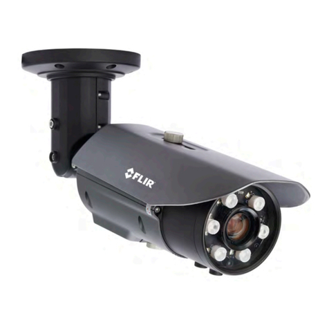
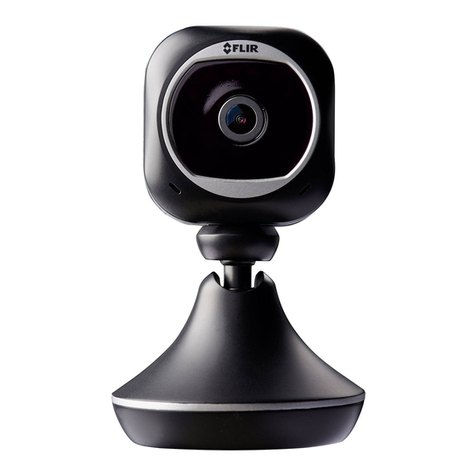
FLIR Quasar CM-6405 User manual

CM-6405 / CM-6408 Quick Install Guide Revision 120
December 2021
This document does not contain any export-controlled information.
Quasar™ Mini-Dome
CM-6405 / CM-6408
Quick Install Guide
1 Check Contents
Make sure all of the items above are included in the camera kit.
2 Select a Location
Select a suitable location to mount the camera.
Verify that the operating temperature range is in the following ranges, with no
more than 90% non-condensing humidity:
·
With heater: -55° C to 60° C (-67° F to 140° F)
·
Cold start with heater: -55° C to 60° C (-67° F to 140° F)
Warnings
·
Placing a camera in a surrounding environment subject to extremely high
temperature can result in an explosion or the leakage of flammable liquid or
gas.
·
Subjecting the camera to extremely low air pressure can result in an explosion
or the leakage of flammable liquid or gas.
·
The camera must be installed by qualified personnel and the installation
should conform to all local codes.
Be sure to have the required accessories and tools available and refer to the
camera's installation and user guide as necessary.
Cables can enter the camera either through the rear of the camera via the
mounting bracket or through a conduit hole on the side of the camera. If the cables
enter through the rear, make sure that the location provides a suitable method for
routing the cables.

CM-6405 / CM-6408 Quick Install Guide Revision 120
December 2021
This document does not contain any export-controlled information.
For further advice on positioning and orienting the camera, see the camera's
installation and user guide.
Supplying Power to the Camera
The camera can be powered by:
·
A UL-listed L.P.S. (Limited Power Supply) unit, rated to a maximum temperature
of 60° C:
o12 VDC, 1.21A minimum
o24 VAC, 50/60Hz, 1.2A minimum
·
PoE (Power over Ethernet): 48 VDC, 0.27A minimum
For assistance with purchasing a power supply, contact Teledyne FLIR.
3 Remove Cover and Separate Base
Tip
When unpacking the camera, do not remove the plastic sheet protecting the
dome.
To remove the dome cover:
a. Using the Torx wrench, loosen the screw on the camera's outer circular ring
that secures the dome cover to the camera base.
b. While firmly holding the base, rotate the ring counterclockwise to loosen it.
c. Carefully pull the ring and cover away from the base.
Outer Ring Locking Screw
Loosen Ring
To separate the camera base from the mounting bracket:
a. Using a screwdriver, loosen the two twist-lock screws securing the camera and
its base to the mounting bracket.
b. Gently pull the camera and its base away from the mounting bracket.
Change the number of LEDs (optional)
The camera has a total of eight IR illumination LEDs. On the 3D lens assembly,
there is a 4 / 8 (default) switch that determines the number of enabled IR LEDs.
With the dome cover removed, you can change the switch setting.

CM-6405 / CM-6408 Quick Install Guide Revision 120
December 2021
This document does not contain any export-controlled information.
Separate Base from Bracket
4 Connect the Camera
To install the camera, Teledyne FLIR recommends connecting the camera on a
bench or in a lab and configuring it for networking before mounting and aiming it.
However, circumstances can dictate adjusting the sequence of the steps. For
example, you can mount the camera before configuring it for networking, or
connect the camera before mounting it.
Warning
The camera itself does not have a power on/off switch. Do
not supply power to the camera until you have completely
finished connecting it.
Connectors
Connector
Connection
1
RJ-45
Two LEDs
Attach a Cat 6 cable from the network switch to the RJ45 connector for a
10/100/1000 Mbps Ethernet and IEEE 802.3af class 0 PoE connection.
Ethernet is required for streaming video and for configuring the camera.
The green link LED indicates a good network connection. The orange
activity LED flashes to indicate network activity.
Warning
The PoE unit and all interconnected equipment must be installed indoors within the same
building, including all PoE-powered network connections, as described by Environment A
of the IEEE 802.3af standard.

CM-6405 / CM-6408 Quick Install Guide Revision 120
December 2021
This document does not contain any export-controlled information.
Connector
Connection
2
Four-pin
power
terminal
block
1
24VAC -
3
12VDC -
If using a 24VAC or 12VDC power
supply, connect it to the power
terminal block connector according
to the pin assignment shown.
2
24VAC +
4
12VDC +
Warning
The power cord to the 12 VDC or 24 VAC power supply unit must be connected to a
socket outlet with an earthing connector.
3
Default
Button
To restore the camera to its factory defaults, use a proper tool to press
the default button for at least 20 seconds.
4
USB
Connects to Wi-Fi dongle (future release support)
5
microSD
Card Slot
For video clip and snapshot recording and file storage, insert a
microSD / SDHC / SDXC card (minimum 8 GB, maximum 512 GB,
Class 10) in the card slot. When the camera is powered on, do not
remove the microSD card.
6
Nine-pin
terminal
block
1
Audio In L
6
Alarm Out +
Attach wires from external devices
to the terminal block connector for
alarm and audio in/out according to
the pin assignment shown.
2
Audio In R
7
Alarm Out -
3
GND
8
Alarm In +
4
Audio Out L
9
Alarm In -
5
Audio Out R
Warnings
·
Do not connect an external power supply to the nine-pin audio/alarm I/O
terminal block connector.
·
This product contains a battery that is soldered to the PCB. There is a risk of
explosion if the battery is replaced by an incorrect type. Do not replace the
battery. The battery should be disposed of in accordance with the battery
manufacturer’s instructions.
Tip
To make it easier to mount and install the camera, while the camera is on the
bench or in the lab, you can connect Ethernet and other cable patch cords to the
camera's connectors and route them through the grommets on the base and
through the mounting bracket. Then, you'll be able to mount and install the
camera without separating the camera base from the mounting bracket a second
time.
5 Configure for Networking
To discover the camera on the network, Teledyne FLIR recommends using the <%
FLIR%> Discovery Network Assistant (DNA) tool. Version 2.3.0.20 or higher
supports Quasar CM-6405 / CM-6408 cameras, does not require a license to use,
and is a free download from the product's web page on the Teledyne FLIR
website. After downloading the DNA ZIP file, extract it.

CM-6405 / CM-6408 Quick Install Guide Revision 120
December 2021
This document does not contain any export-controlled information.
You can configure the camera using the DNA tool, the camera's web page, or a
supported VMS.
DNA tool
Camera's web page
Discover camera IP address
•
Configure IP address, mask, and gateway
•
•
Configure DNS settings, MTU, and Ethernet speed
•
Change user credentials
•
•
Change video format
•
•
Configure more than one camera at the same time
•
For information about using the camera's web page to configure the camera, see
the camera's installation and user guide. For information about using a supported
VMS to configure the camera, see the VMS documentation.
By default, DHCP is enabled on the camera and a DHCP server on the network
assigns the camera an IP address. For example, if the camera is managed by
Teledyne FLIR's Horizon or Meridian VMS and the VMS is configured as a DHCP
server, the VMS automatically assigns the camera an IP address.
If the camera is managed by Teledyne FLIR’s Latitude VMS or is on a network
with static IP addressing, you can manually specify the camera’s IP address using
the DNA tool or the camera's web page. The camera's default IP address is
192.168.0.250.
To manually specify the camera's IP address using the DNA tool:
a. Make sure the camera and the PC are on the same LAN segment.
b. Run the DNA tool (DNA.exe) by double-clicking .
The Discover List
appears, showing
compatible
devices on the
LAN segment and
their current IP
addresses.
In the DNA Discover List, verify that the camera's status is Online.
If this is the first time you are configuring the camera or if it is the first time after
resetting the camera to its factory defaults, DNA automatically authenticates
the camera with the default password for the camera's admin user (admin).
If the admin user password has been changed, you need to authenticate the
camera.
In the DNA Discover List, right-click the camera and select Login.
In the DNA - Login window, type the password for the admin user. If you do
not know the admin user password, contact the person who configured the
camera's users and passwords.
Click Login, wait for Ok status to appear, and then click Close.

CM-6405 / CM-6408 Quick Install Guide Revision 120
December 2021
This document does not contain any export-controlled information.
In the DNA Discover List, verify that the camera's status is Authenticated.
c. Change the camera’s IP address.
Right-click the camera and select IP Setup.
In the DNA - IP Setup window, clear Use
DHCP and specify the camera's IP
address. You can also specify the Mask
(default: 255.255.255.0) and Gateway.
Then, click Update, wait for Ok status
to appear, and then click Close.
6 Change Video Format (Optional)
By default, NTSC is the camera's video format.
To change the camera's video format to
PAL using the DNA tool:
a. In the DNA Discover List, right-click the
camera and select Change Video Format.
b. In the Change Video Format window,
select PAL.
c. Click Update, wait for Ok status to
appear, and then click Close.
For more information about using the DNA tool to configure one or more cameras,
see the DNA User Guide. While the software is open, click the Help icon
.
For the camera's other default Video Configuration settings, see 7 Default Video
Configuration Settings.
7 Re-attach Cover
To prevent damaging the camera's internal components while moving it from the
bench or lab to its mounting location, re-attach the dome cover to the base and
then remove it again at the mounting location.
Before doing so, you can re-attach the camera base to the mounting bracket. Use
a screwdriver to tighten the two twist-lock screws securing the camera and its
base to the mounting bracket. If you do not re-attach the camera base to the
mounting bracket, remember to bring the screwdriver to the mounting location.

CM-6405 / CM-6408 Quick Install Guide Revision 120
December 2021
This document does not contain any export-controlled information.
To re-attach the dome cover:
a. Using the two guide pins on the dome cover and the triangles on the cover and
on the base, carefully align and position the dome cover onto the base.
b. Securely tighten the outer ring.
c. Lock the ring. Using the Torx wrench, tighten the screw on the outer ring that
secures the cover to the base.
8 Fit Mounting Hardware
If required, install the mounting hardware for the camera according to the
instructions for the hardware.
9 Remove Cover and Separate Base
Repeat the steps described in 4.2 Remove Cover and Separate Base.
10 Install Mounting Bracket
You can install the mounting bracket on standard electrical boxes or directly on a
secure, flush, and vibration-free surface.
To install the mounting bracket on a standard electrical box:
Attach the bracket to the box using:
·
The holes in the mounting bracket,
according to the types of boxes engraved on
the bracket
·
The corresponding holes in the box
·
Suitable bolts, washers, and nuts (not
included in the camera kit)
To install the mounting bracket directly on
a surface:
a. Choose four widely spaced mounting holes
on the bracket for optimum flat surface mounting.
b. Using the bracket as a template to mark the surface, drill four anchor holes.
c. (Optional) If necessary, drill a hole wide enough for routing cables.
d. Hammer the four plastic screw anchors into the drilled holes.
e. Insert the anchors and then attach the bracket to the surface using the four M4
25mm self-tapping screws included in the camera kit.
When tightening the screws, the holes in the mounting plate allow for making small
adjustments to the bracket's position.
CM-6405 / CM-6408 Quick Install Guide Revision 120
December 2021
This document does not contain any export-controlled information.
11 Route Cables and Connect the Camera
Cables can enter the camera from the side or from the rear.
To route cables through the side of the
camera:
a. Use the Torx wrench to loosen the
screw securing the side conduit hole
cover and remove the hole cover.
b. Route cables through the hole.
To route cables through the rear
of the camera:
a. Route cables through the hole
in the mounting bracket.
To route cables into the camera base:
a. For each cable, use the Torx wrench to punch a hole in the center of the rubber
glands in the the camera's base, from the underside.
b. Route the cable through the hole in the grommet.
c. Push the cables back through the seal so that the seal extends out of the base.
Inside base
According to the information in 4 Connect the Camera, connect the camera.
Note
Connect the camera to a 24VAC or PoE power source as the primary power
source, and then connect 12VDC as the secondary power source. If the primary
power source fails, the camera seamlessly switches to 12VDC until the primary
power source is restored.
12 Mount and Aim the Camera
a. Make sure that the camera is facing the required field of view. Then, carefully
re-attach the camera base to the mounting bracket. Use a screwdriver to
tighten the two twist-lock screws securing the camera and its base to the
mounting bracket.
b. Aim the camera, which has three axes for adjusting the field of view:
oPan adjustment – Rotate the lens base until satisfied with the field of view.
oTilt adjustment – Loosen the screw locking the camera lens in its tilt angle. Tilt
the lens until satisfied with the field of view. Then, tighten the screw.
oLens rotation – Rotate the 3D assembly in the lens until satisfied with the field
of view.

CM-6405 / CM-6408 Quick Install Guide Revision 120
December 2021
This document does not contain any export-controlled information.
Aiming the Camera
Caution
Do not rotate or tilt beyond the mechanical limits for each axis:
·
Pan adjustment range: 356°
·
Tilt adjustment range: ±80°
·
Lens rotation range: ±98° – Rotating the 3D assembly in the lens beyond
its mechanical limit can twist, disconnect, or break the camera's internal
cables.
When adjusting the tilt and lens rotation for a CM-
6408-11-I camera, at the camera's widest view
(zoom = 1x) and at certain tilt angles, as shown
at right, a small part of the camera can appear in
the far upper-left corner of the field of view.
Tilt angle
Lens rotation
angle range
20°
30°~45°
10°
10°~45°
c. Repeat the steps described in 4.6 Re-attach Cover.
13 Complete Camera Setup
Specify the camera's zoom and focus, and format the microSD card, using the
camera's web page. Teledyne FLIR recommends using Microsoft Internet Explorer
11.0, with the ActiveX plug-in.
The camera's web page supports other browsers that do not support ActiveX.
However, using another browser requires configuring MJPEG encoding for at least
one of the camera's video streams; for more information, see the camera's
installation and user guide.
Windows Security dialog box
a. Log in to the camera’s web page.
In the DNA Discover List, double-click the
camera.
In the Windows Security dialog box, type a
user name and password. Both are case-
sensitive.
When logging in to the camera's web page
for the first time or for the first time after
resetting the camera to its factory defaults,
type admin for the user name and for the
password.

CM-6405 / CM-6408 Quick Install Guide Revision 120
December 2021
This document does not contain any export-controlled information.
Then, specify a new password for the admin user. Use a strong password
consisting of 8-64 characters. Passwords can include special characters
@#~!$&<>+_-.,*?.
Log back in using the new password.
b. If the User Account Control dialog opens and prompts you to install the
install.cab file, click Yes.
If ActiveX installation is not successful, in the
Internet Explorer Tools > Internet Options >
Advanced Security settings, select Allow software
to run or install even if the signature is invalid and
click OK. Try installing ActiveX again. After a
successful ActiveX installation, uncheck the
checkbox, and click OK.
If a popup message appears for running the ActiveX add-on, click Allow.
c. Install the web player.
Note
If you have previously installed a web player application on the PC, you
should delete the existing web player from the PC before accessing the
camera. For information on how to install the new player, uninstall a previous
player, and clear temporary Internet files, see the camera's installation and
user guide.
The camera's web page opens.
d. On the Live page, adjust the zoom or focus using the controls.

CM-6405 / CM-6408 Quick Install Guide Revision 120
December 2021
This document does not contain any export-controlled information.
b. Format the microSD card.
From the navigation bar, click Settings.Then, in the sidebar, click System >
Edge Recording > SD Card.
Under Device Setting, you can select vfat (default) or ext4 (recommended).
Click Format.
14 Default Video Configuration Settings
The camera's default Video Configuration settings appear in the following image.
CM-6405: 2688x1944 is the default stream1 resolution.
Default Video Configuration Settings - CM-6408
For more information about using the camera's web page to configure the camera,
see the camera's installation and user guide.
15 Attach the Camera to a Supported VMS
After mounting the camera and discovering or defining its IP address, use VMS
Discovery/Attach procedures to attach the camera to a supported VMS.

CM-6405 / CM-6408 Quick Install Guide Revision 120
December 2021
This document does not contain any export-controlled information.
16 Camera Dimensions
17 Register the Product
Register the product at https://customer.flir.com.
For warranty information, see https://www.flir.com/support-
center/warranty/security/flir-security-product-warranties/.
18 Contact Information
Americas
6769 Hollister Avenue
Goleta, CA 93117
USA
Support: https://support.flir.com/
27700 SW Parkway Ave.
Wilsonville, OR 97070
USA
Other manuals for Quasar CM-6405
2
This manual suits for next models
1
Table of contents
Other FLIR Security Camera manuals

FLIR
FLIR P143E4 SERIES User manual

FLIR
FLIR Quasar CB-6404 User manual

FLIR
FLIR PT series User manual

FLIR
FLIR DIGIMERGE DBD24TL User manual

FLIR
FLIR FX User manual

FLIR
FLIR FC-Series Assembly instructions

FLIR
FLIR DEZ06T10 User manual

FLIR
FLIR FC-Series S User manual

FLIR
FLIR DBV54TL User manual

FLIR
FLIR Ariel Gen III CB-3304 User manual

FLIR
FLIR FB-Series Assembly instructions

FLIR
FLIR CP-6302-30-R User manual

FLIR
FLIR F-348 User manual

FLIR
FLIR PT series User manual

FLIR
FLIR PTZ-35 MS User manual

FLIR
FLIR FXV101-W User manual

FLIR
FLIR SR-124 User manual

FLIR
FLIR G300 A User manual

FLIR
FLIR DBV533TL User manual

FLIR
FLIR DND13TL2 User manual