B. Prepare for Camera installation
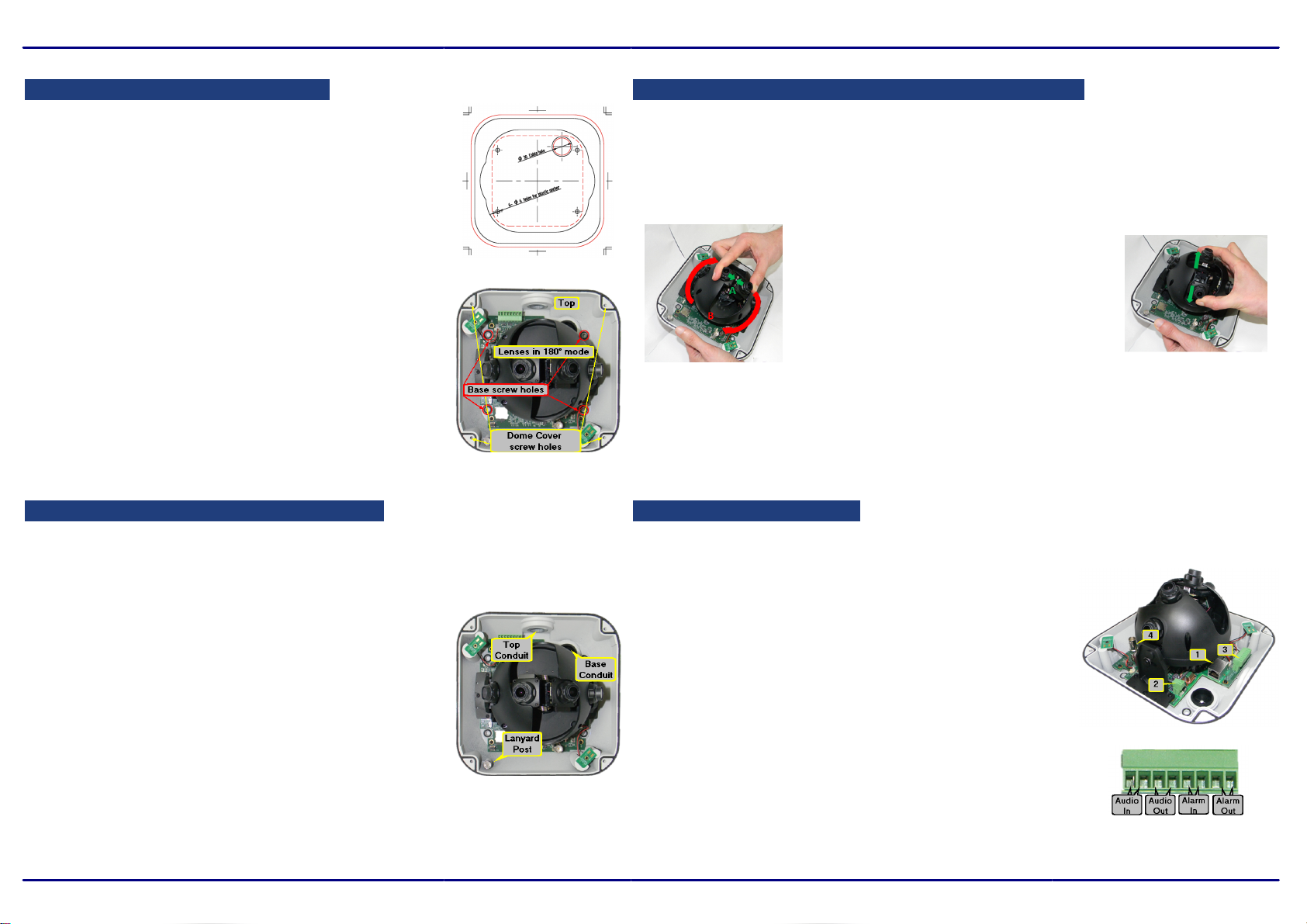
C. Change the camera from 180° to 360° if required.
1. Verifythat the operating temperature range is between
-40°C ~ 50°C (-40° ~ 122°F), 0-90% relative humidity(non-
condensing).
2. Be sure to have the required accessories and tools available.
Refer to the User and Installation Guide.
3. Place the supplied drill template over the installation surface.
4. Drill four holes into the surface.
5. Using the supplied Torx wrench, unscrew the four screws
on the dome cover and remove the cover.
6. Once the cover is removed, you will notice plastic lens covers
with red arrows; these arrows point to the top part of the
camera (which is where the top conduit connection is).
These covers should only be removed right before the dome
cover is replaced.
7. The camera is shipped with the lenses mounted for 180°
viewing (Wall Mode).
If the camera is required to operate in 360° mode, the lens must be physically rotated
to Ceiling Mode.
No change is required in the camera's user interface.
To re-position the lenses
1. Hold the two inner lenses together from
the base and rotate them clockwise.
Be sure to leave the protective lens caps
on the lenses during this step.
2. Gently release the lenses until the spring is
fully released.
3. Remove the lens caps.
4. The camera reboots in Ceiling Mode
(360° operation).
D. Mount the camera base on the surface
1. Align the holes on the camera's base plate with
the drilled holes.
2. Screw the base into the installation surface.
3. Attach the Cables (see right)
4. Tighten the screws after all cables are inserted so that
the base plate is flush with the surface.
Notes:
1. When mounting the camera in 180° mode, note the position of the
Top Conduit to orientate the camera correctly.
2. Depending on w here the camera is to be mounted and how
the cables are routed to it, feed and attach the cables
before or after mounting the camera in its final position.
1. Insert the leads from the required system cables into their
connectors.
a. RJ45 connector to Category 5 or 6 cable for network
and IEEE 802.3at PoE+ connection.
(Note - PoE+ is required if powered on the netw ork)
b. Two-pin terminal block connector for leads to
optional external 24VAC power supply (not provided).
c. 8-pin terminal block connector for leads to
alarm and audio I/Os. (see detail)
d. BNC connector for 75-ohm video cable for
analog audio out in 360° (Ceiling) Mode.
2. Unscrew the cover over the Top or Base cable conduits
and feed the system cables through it.
3. To maximize water protection when using conduit, use
the included rubber O-ring and add teflon tape to the
threading.


