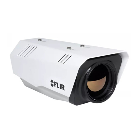
FLIR Nexus User manual

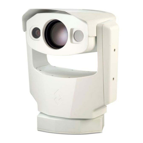
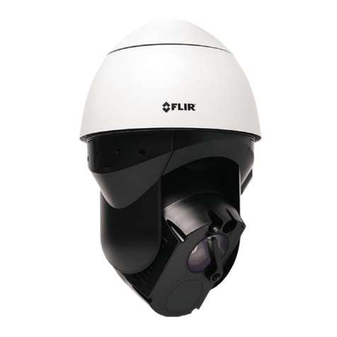
Nexus IP Camera
Configuration Guide
FLIR Commercial Systems, Inc.
70 Castilian Drive
Goleta, CA 93117
Phone: 888.747.FLIR (888.747.3547)
International: +1.805.964.9797
www.flir.com
Document Number: 427-0030-00-28
Version: 100
Issue Date: January 2012
This document is controlled to FLIR Technology Level 1. The information contained in this document pertains to a dual use product controlled for
export by the Export Administration Regulations (EAR). FLIR trade secrets contained herein are subject to disclosure restrictions as a matter of law.
Diversion contrary to US law is prohibited. US Department of Commerce authorization is not required prior to export or transfer to foreign persons
or parties unless otherwise prohibited.

Nexus Configuration Guide
-ii January 2012 427-0030-00-28, version 100
© FLIR Commercial Systems, Inc., 2011. All rights reserved worldwide. No parts of this manual, in whole or in part,
may be copied, photocopied, translated, or transmitted to any electronic medium or machine readable form without the
prior written permission of FLIR Commercial Systems, Inc.
Names and marks appearing on the products herein are either registered trademarks or trademarks of FLIR
Commercial Systems, Inc. and/or its subsidiaries. All other trademarks, trade names, or company names referenced
herein are used for identification only and a100re the property of their respective owners.
This product is protected by patents, design patents, patents pending, or design patents pending.
The Nexus thermal imaging system is controlled by US export laws. There are special versions of this system that are
approved for international distribution and travel. Please contact FLIR Systems if you have any questions.
FLIR Commercial Systems, Inc.
70 Castilian Drive
Goleta, CA 93117
Phone: +1.888.747.FLIR (+1.888.747.3547)
http://support.flir.com/
http://www.flir.com/training

427-0030-00-28, version 100 January 2012 -iii
Table of Contents
1 Nexus IP Camera Configuration
1.1 Warnings and Cautions ....................................................................... 1-1
1.2 Introduction ....................................................................................... 1-2
1.3 Nexus IP Camera ................................................................................ 1-2
1.4 Camera Configuration .......................................................................... 1-2
1.5 Serial and/or IP Communications ......................................................... 1-3
1.6 Serial Communications ....................................................................... 1-3
1.7 System Information Displayed at Startup ................................................ 1-4
1.8 FLIR Certified Systems Integrator (FCSI) Training ..................................... 1-4
2 Verify Camera Operation with FSM
2.1 Power and analog video ....................................................................... 2-1
2.2 Verify IP Communications ..................................................................... 2-1
2.3 Using FLIR Sensors Manager (FSM) ...................................................... 2-2
2.3.1 Running FSM ............................................................................. 2-2
2.4 Troubleshooting Tips ........................................................................... 2-5
2.4.1 Camera not discovered ................................................................ 2-5
2.4.2 Unable to control the camera ....................................................... 2-6
2.4.3 General Errors ........................................................................... 2-7
2.4.4 Unable to View Video Stream ........................................................ 2-7
2.5 Restoring the Factory Network Settings ................................................. 2-9
3 Web Configuration Tool
3.1 Web Configuration Overview ................................................................. 3-1
3.1.1 Web Configuration Tool login ........................................................ 3-1
3.1.2 Saving Configuration Changes ....................................................... 3-3
3.1.3 Restarting the Server .................................................................. 3-3
4 Nexus Camera Configuration
4.1 IP Communications ............................................................................. 4-1
4.1.1 IP Configuration Steps ................................................................. 4-1
4.2 Basic Web Configuration ..................................................................... 4-2
4.3 Settings ............................................................................................ 4-2
4.4 LAN Settings ..................................................................................... 4-3
4.4.1 D-Series LAN Settings ................................................................. 4-4
4.5 Server Status ..................................................................................... 4-5
4.5.1 Setting the Date and Time ............................................................ 4-5
4.5.2 Software Upgrades ..................................................................... 4-5

Nexus Configuration Guide
-iv January 2012 427-0030-00-28, version 100
4.5.3 Rebooting the Camera ................................................................. 4-5
4.6 Serial Remote .................................................................................... 4-6
4.6.1 Serial Extensions ........................................................................ 4-7
4.6.2 Preset Map File .......................................................................... 4-7
4.6.3 AutoPan Function ....................................................................... 4-8
4.7 Network Remote / VMS ..................................................................... 4-9
4.7.1 ONVIF ....................................................................................... 4-9
4.8 Video IR .......................................................................................... 4-10
4.8.1 RTP Settings ............................................................................ 4-11
4.8.2 Network Options (Unicast/Multicast) ...........................................4-11
4.8.3 Settings .................................................................................4-12
4.9 Video DLTV ..................................................................................... 4-13
4.10 Video Matrix .................................................................................. 4-14
4.11 OSD (On Screen Display) .................................................................. 4-15
4.12 Log File ......................................................................................... 4-16
4.13 Configuration File ............................................................................ 4-17
4.14 Help ............................................................................................. 4-18

427-0030-00-28, version 100 January 2012 1-1
1 Nexus IP Camera Configuration
This manual provides a brief guide to configuration of FLIR Nexus IP cameras. If you need help
during the installation and configuration process, contact your local FLIR representative or, call
877-773-3547 inside the US.
For specific information about how to mount and connect the camera, refer to the installation
manual provided with the camera.
This manual includes the following topics:
• Camera configuration overview
• Web Configuration Tool
• Bench testing the camera
• Troubleshooting Tips
• Basic configuration of the camera
For safety, and to achieve the highest levels of performance from the system, always follow the
warnings and cautions in this manual when handling and operating the camera.
1.1 Warnings and Cautions
WARNING!
Caution!
If mounting the camera on a pole, tower or any elevated location, use industry standard safe
practices to avoid injuries.
Except as described in this manual, do not open the camera for any reason. Disassembly of
the camera (including removal of the cover) can cause permanent damage and will void the
warranty.
Be careful not to leave fingerprints on the camera’s infrared optics.
Operating the camera outside of the specified input voltage range or the specified operating
temperature range can cause permanent damage.

1—Nexus IP Camera Configuration Nexus Configuration Guide
1-2 January 2012 427-0030-00-28, version 100
1.2 Introduction
The FLIR Nexus IP Camera is both an analog camera and an IP camera. In general, the camera
is configured using a web browser to access the Web Configuration Tool, and this guide
provides information about how to use that web tool.
The video from the camera can be viewed over a traditional analog video network, and it can be
viewed by streaming it over an IP network using MPEG-4, M-JPEG and H.264 encoding. Analog
video requires a connection to a video monitor or an analog matrix/switch. The IP video will
require a connection to an Ethernet network switch, and a computer with the appropriate
software for viewing the video.
Some cameras can be controlled through either serial or IP communications. For a camera
that uses serial communications, those settings can be configured using hardware DIP
switches instead. The configuration of serial communications parameters using hardware DIP
switches is described in the installation manual for the camera, rather than this document.
1.3 Nexus IP Camera
When a camera has Nexus capabilities, that means there is a microprocessor inside that runs
the Nexus server software. The Nexus server provides a number of services, including camera
control, video streaming, and geo-referencing capabilities. The Nexus communications protocol
is an open, standards-based protocol that allows the camera to communicate with a video
management client, such as FLIR Sensors Manager or with a third-party ONVIF-compatible
Video Management System (VMS) client.
Custom VMS applications can be developed using the open Nexus Software Developers Kit
(SDK) components. Applications can also be developed using Extensible Markup Language
(XML) or Common Gateway Interface (CGI) tools.
There are two main components to the Nexus Server software. One is a web server known as
the Web Configuration Tool that listens on the network for web browser requests, and is used
for the initial (and perhaps ongoing or occasional) configuration changes to the camera. The
other process, known as the Nexus Server, listens on the network for connections from clients
such as FSM or other VMS clients. These clients are used to control the camera and stream
video during day-to-day operations of the camera.
1.4 Camera Configuration
In general, it may be necessary for the installer to make a limited number of configuration
changes for each camera, such as setting the serial and/or IP communication parameters.
For example, each camera comes from the factory with the same default IP address, so adding
more than one camera to an IP network requires each camera to be configured with a different
IP address, at a minimum. On the other hand, many of the configuration parameters will
remain unchanged from the factory default settings. This document provides a brief guide to
setting the configuration parameters which are most commonly changed in order to get the
camera to communicate and to operate normally.
In order to control the camera, it is necessary to communicate with it either over serial
communications (RS-232 or RS-422), or over Ethernet using Internet Protocol (IP). In either
case, it is likely there are some communication parameters that are specific to each
installation.

Nexus Configuration Guide 1—Nexus IP Camera Configuration
427-0030-00-28, version 100 January 2012 1-3
1.5 Serial and/or IP Communications
For a camera that is installed in a legacy-type CCTV network using analog video, the camera will
commonly be controlled with serial communications. The serial cable from the camera will be
connected to a keyboard/joystick device, or to a video switch or DVR that has a serial
communication port. In this case the installer may want to configure parameters such as the
address of the camera, the baud rate, and so on. These parameters can be set either using
hardware DIP switches or through software using a web browser.
For a camera installed in an IP network, the camera will commonly be controlled over Ethernet
by a PC or laptop running FLIR Sensors Manager (FSM) or a third-party Video Management
System (VMS) software. FSM is an integral part of the Nexus architecture—it is a client
program that communicates with the Nexus server on the camera. It allows control of the
camera and video streaming and many other sophisticated functions.
In many cases, a camera will be installed with both serial and Ethernet communications. As
such, the camera can be controlled by means of a serial device or through software. When
someone tries to control the camera with a serial device at the same time as someone does
through the software IP interface, the serial device takes priority.
If serial control is used, the installer must first decide if the serial communications settings will
be configured via hardware (DIP switch settings) or software.
If the camera does not have an Ethernet connection, the DIP switches must be used to set the
serial communication options. In the future, configuration changes may require accessing the
camera on a tower or pole, dismounting it, and removing the back and so on. Refer to the
camera installation manual for information about setting the switches.
For a camera installed in an IP network, configuration changes (including settings related to
serial communications) are made using a web browser. If the camera has an Ethernet
connection, generally it will be easier (and more convenient in the long run) to make
configuration settings via software. Then configuration changes can be made over the network
without physically accessing the camera. Also the settings can be saved to a file and backed up
or restored as needed.
Refer to Chapter 3 “Web Configuration Tool” on page 3-1 for general information about the web
interface and about saving configuration changes. For specific configuration information, refer
to Chapter 4 “Nexus Camera Configuration” on page 4-1.
Not all parameter settings are described in these sections. If you need help during the
configuration process, contact your local FLIR representative or, call 877-773-3547 inside the
US.
1.6 Serial Communications
Cameras that have a serial interface support a limited set of zoom and focus commands over
RS-422 or RS-232 serial communications using common protocols (Pelco D or Bosch). By
default, the camera is configured for RS-422 standard, 9600 Baud, 8 bits, no parity, 1 stop
bit, using the Pelco D protocol, and address 1, and configuration changes are made with a web
browser, rather than DIP switches.
A single DIP switch (SW102-9, Software Override) determines whether the serial
communications configuration comes from the hardware DIP switches or the software
settings. By default the configuration comes from software settings.
1—Nexus IP Camera Configuration Nexus Configuration Guide
1-4 January 2012 427-0030-00-28, version 100
If you are using the IP interface to configure the serial communication settings for the camera,
refer to section 4.6 “Serial Remote” on page 4-6.
1.7 System Information Displayed at Startup
When the camera is turned on, the video temporarily displays system information including the
serial number, IP address, Pelco address, Baud rate, and setting of the serial control DIP
switch: SW - software control (the default) or HW - hardware.
S/N: 1234567
IP Addr: 192.168.250.116
PelcoD (Addr:1): 9600 SW
1.8 FLIR Certified Systems Integrator (FCSI) Training
This configuration guide provides a brief description of the configuration parameters that are
available through the basic user login. For installers and integrators that are interested in a
more advanced level of configuration, the FLIR Certified Systems Integrator (FCSI) certification
program offers hands-on training with a variety of FLIR cameras, and focuses on integration
design and installation with other third-party security sensors and equipment. For more
information, contact your local FLIR representative or visit one of the following web sites:
http://support.flir.com/
http://www.flir.com/training
The DIP switches are only used to control serial communications parameters. Other settings,
related to IP camera functions etc., must be modified via software (using a web browser).

427-0030-00-28, version 100 January 2012 2-1
2 Verify Camera Operation with FSM
This chapter provides information on how to perform a bench test with a new camera that has
not yet been configured. A bench test can be used to verify camera operation before the
camera is configured for the local network.
2.1 Power and analog video
Install the camera cables as described in the installation manual. Apply power to the camera
and confirm it is supplying video to the monitor.
After the camera is turned on and finishes the bootup process (after approximately 90
seconds), the video temporarily displays system information including the serial number, IP
address, Pelco address, Baud rate, and the setting of the Software Override DIP switch: SW -
software control (the default) or HW - hardware.
S/N: 1234567
IP Addr: 192.168.250.116
PelcoD (Addr:1): 9600 SW
2.2 Verify IP Communications
As shipped from the factory, the Nexus camera has an IP address of 192.168.250.116 with
a netmask of 255.255.255.0.
Step 1 Configure a laptop or PC with another IP address from this network (for example,
192.168.250.1).
Step 2 Connect the camera and the laptop to the same Ethernet switch (or back-to-back with
an Ethernet crossover cable).1
Step 3 Open a web browser2,
enter http://192.168.250.116 in the
address bar, and press Enter.
.The Web Configuration tool will start at the Login screen.
The Login screen shows a picture of the camera and allows
you to enter a User and Password. The login screen for the
F-Series camera appears to the right.
If the Login screen appears, then you have established IP
communications with the camera.
At this time, it is recommended a bench test of the camera
should be performed with the FLIR Sensors Manager
software, using the camera’s factory-configured IP address.
1. In some cases, a straight Ethernet cable can be used, because many PCs have auto detect
Ethernet interfaces.
2. FLIR Web Configuration Tool is optimized for Microsoft Internet Explorer; other web browsers
may not work as well.

2—Verify Camera Operation with FSM Nexus Configuration Guide
2-2 January 2012 427-0030-00-28, version 100
2.3 Using FLIR Sensors Manager (FSM)
The following provides a brief description of how to use FSM to control a camera and stream
video from the camera. For more detailed information on how to use FSM, refer to the FLIR
Sensors Manager User Manual (the manual is available as a pdf file from the Start menu, once
the software is installed).
If the FSM software has not been installed yet, locate the CD that came with the camera and
install it on the PC. The latest version of FSM can be dowloaded at http://ns.flir.com.
The installer must have administrative privileges on the PC to install the software and to grant
network access if the Personal Firewall is enabled.
2.3.1 Running FSM
Run the FSM software by double clicking the icon on the desktop, or click on the
Windows Start button and select Programs > FLIR Sensors Manager > FLIR
Sensors Manager.
Initially the FLIR Sensors Manager splash screen will be displayed. The software version may be
different than the version displayed below.

Nexus Configuration Guide 2—Verify Camera Operation with FSM
427-0030-00-28, version 100 January 2012 2-3
After a brief while, the FSM main window will appear, and a popup FSM Notification window will
appear in the lower right of the screen indicating that no cameras (servers) have been
discovered yet.
Click on the Accept button to acknowledge the notification.
The FLIR Sensors Manager uses a type of “client/server”
architecture. The FSM software is considered a client, and
the cameras are considered servers (also known as
sensors). Note, in this client/server model there may be
many servers (cameras), and the servers are decentralized since they are distributed around
the network.
The Sensors Panel in the upper left of the window
indicates no sensors have been discovered and added to
the list of Active Sensors. The FSM software can
automatically discover FLIR cameras and other sensors
on the network. Each FSM user can choose to add one or
more discovered sensors to the Sensors Panel as needed.
Use the following steps to add the camera to the Sensors Panel, and to verify the operation of
the camera by opening up a video stream and controlling the camera.
Step 1 Select the Setup tab along the top of the window (it may be selected already by
default) and then the Discovery button on the right side panel to bring up the
Discovery Panel.
Step 2 When the Discovery Panel is displayed, click the Refresh button.
The FLIR camera will appear in the list of Discovered Servers1. The asterisk in
parenthesis “(*)” indicates the camera has not been added to the list of Active
Servers on the right.
Step 3 In the Discovered Servers list, click on the name of the camera to select it, and then
click on the center bar “>” to move the camera over to the list of Active Servers on
the right.
By default, the FSM software will automatically:
• discover sensors in the network,
• connect to the first camera it finds,
• take control of the camera, and
• display the video from the camera in Video Wall 0.
1. If the camera is not displayed in the list of Discovered Sensors, there could be a problem with
the network, the PC, or the camera. See “Troubleshooting Tips” on page 2-5.

2—Verify Camera Operation with FSM Nexus Configuration Guide
2-4 January 2012 427-0030-00-28, version 100
Step 4 Select the Video Wall 0 tab and confirm that video is streamed to the monitor.
Step 5 Confirm it is possible to control the camera using buttons in the Control Panel. For
example, click on the zoom in button (magnifying glass with +), and the video will zoom
to 2X. For a pan/tilt camera, use the up/down and pan left/right controls to move
the camera.
Once you have verified the basic operation of the camera and successfully streamed video, you
may want to make some configuration changes. For example, the camera can be configured
with an IP address that matches the installation network. Refer to Chapter 4.1 “IP
Communications” on page 4-1for a brief guide on how to configure the camera.
When you are ready to install the camera in its final location, confirm the cables are properly
attached and the DIP switches are set as desired. Reassemble the rear cover after confirming
the ground wire is connected properly, and tighten the cable gland nuts to ensure a good seal
all around.
Discovery
No Sensors Discovered Setup
Refresh
Move to Active Servers listControl Panel Select camera name

Nexus Configuration Guide 2—Verify Camera Operation with FSM
427-0030-00-28, version 100 January 2012 2-5
2.4 Troubleshooting Tips
If you need help during the installation process, contact your local FLIR representative or, call
877-773-3547 inside the US.
Before using serial communications, it may be necessary to configure the camera’s serial
interface to operate with the other serial device. For more information, refer to section 4.6
“Serial Remote” on page 4-6.
2.4.1 Camera not discovered
By default the camera will broadcast a “discovery” packet two times per second. When FSM
starts up, it listens to the network for the discovery packets. If no cameras are listed in the
Discovered Servers list, press the Refresh button. If the list is still empty, it indicates no
discovery packets were received. This could be due to a wide variety of problems with the
network, the PC, or the camera.
First check to ensure the physical connections are intact and that the camera is powered on
and providing analog video to the monitor. When the camera is turned on, confirm the startup
information is displayed on the analog monitor after approximately 90 seconds. For example:
S/N: 1234567
IP Addr: 192.168.250.116
PelcoD (Addr:1): 9600 SW
Confirm that the IP address for the PC (for example, 192.168.250.1) is on the same network
as the camera.
Next determine if Windows Personal Firewall is blocking the packets. You can turn off the
firewall or add an exception for the FSM program. Typically when FSM runs for the first time, a
pop-up notification may ask for permission to allow the FLIR Sensors Manager (fsm.exe) to
communicate on the network, as in the following notification. Select the check boxes that are
appropriate for your network.
If necessary, use a packet sniffer utility such as Wireshark to capture packets and confirm the
packets are being received by the PC from the camera.

2—Verify Camera Operation with FSM Nexus Configuration Guide
2-6 January 2012 427-0030-00-28, version 100
2.4.2 Unable to control the camera
If you are unable to control the camera with serial communications, ensure the communication
parameters of the camera (such as baud rate, address, and communication standard) match
the parameters of the other serial device. If using RS-422, confirm the receive pair on the
camera are connected to the transmit pair of the other device. Also confirm that the Software
Override DIP switch (SW102-9) is set correctly. This switch determines whether the serial
configuration comes from the hardware DIP switches or the software settings. Refer to the
camera installation manual for information on how to set the DIP switches.
If the camera does not respond to commands from FSM (for example, the camera does not
zoom when the zoom in button is clicked), the camera may not be the “Active” camera, or you
may not have control of the camera. By default FSM will automatically request control of the
camera and make it active, but if there are multiple cameras and/or multiple FSM clients, it
may be necessary to manually make the camera active and take control of it.
In the Sensors Panel, if the camera is the active sensor, there will be an
“(Active)” notification next to the name of the camera. Only one camera or
sensor can be active at a time. To make the camera active, right click on the
icon to the left of the camera name and select “Set Active”, or simply double-
click on the icon.
The icon to the left of the camera name indicates the status of the sensor. The following is a list
of the possible icons and the meaning of each one.
Connected and Controlled
This icon indicates the camera has been discovered and added to the list of active servers, and
the camera is actively “connected” to the FSM client and receiving status updates. The joystick
in the icon indicates the user has control of the camera. To release control of the camera, right
click on the icon and select “Release Control”.
Discovered
This icon indicates the camera has been discovered and added to the list
of active servers, but the camera is not actively “connected” to FSM, and
therefore FSM is not receiving status updates. To connect to the camera,
right click on the icon and select “Connect”. Alternatively, it is possible to
double-click the icon to connect.
Connected
This icon indicates the camera has been discovered and added to the list
of active servers, and the camera is actively “connected” to FSM and
receiving status updates. To take control of the camera, right click on the
icon and select “Request Control”. Alternatively, it is possible to double-
click the icon to take control.
Not Connected
This icon indicates the camera has been discovered and added to the list of active servers, and
the camera is actively “connected” to the FSM client and receiving status updates. To connect
to the camera, right click on the icon and select “Connect”.

Nexus Configuration Guide 2—Verify Camera Operation with FSM
427-0030-00-28, version 100 January 2012 2-7
2.4.3 General Errors
In the status bar at the bottom of the screen there may be an indication that an error has
occurred. When you position the cursor over the error icon (exclamation mark), the error will
be displayed in a temporary pop-up. It is possible to view all the error messages by selecting the
Tools tab at the top of he screen, and then select the Log button to the left.
2.4.4 Unable to View Video Stream
If the video stream from the camera is not displayed in FSM, it could be that the packets are
blocked by the firewall, or there could be a conflict with video codecs that are installed for other
video programs.
When displaying video with FSM for the first time, the Windows Personal Firewall may ask for
permission to allow the FLIR Video Player (vp.exe) to communicate on the network, as in the
following notification. Select the check boxes that are appropriate for your network.

2—Verify Camera Operation with FSM Nexus Configuration Guide
2-8 January 2012 427-0030-00-28, version 100
If necessary, test to make sure the video from the camera can be viewed by a generic video
player such as VLC media player (http://www.videolan.org/vlc/).To view the video stream,
specify RTSP port 554 and the appropriate stream name such as “ch0”. For example:
rtsp://192.168.250.116:554/ch0)

Nexus Configuration Guide 2—Verify Camera Operation with FSM
427-0030-00-28, version 100 January 2012 2-9
2.5 Restoring the Factory Network Settings
The camera comes configured from the factory with a default IP address (192.168.250.116).
In some cases, it may be necessary to restore the network settings of the camera to the
original factory settings. If necessary, the camera IP address can be restored to this factory
default address by connecting a loopback device to the Ethernet port.
At each power-up, the system transmits a packet and then checks to determine if that same
packet has been received. Detection of the received packet indicates the camera has a custom
loopback connector installed on its Ethernet interface. The detection of the loopback packet
cues the camera to restore Factory Defaults and to revert to the same configuration and
behavior as when the camera left the factory.
The custom loopback connector is described below.
The RJ45 loopback termination ties pin 1 to pin 3, and pin 2 to pin 6. The other pins are not
connected.
Pin # Signal Tied to pin #
1Transmit+ 3
2Transmit- 6
3 Receive + 1
4Unused N/A
5Unused N/A
6 Receive - 2
7Unused N/A
8Unused N/A

2—Verify Camera Operation with FSM Nexus Configuration Guide
2-10 January 2012 427-0030-00-28, version 100

427-0030-00-28, version 100 January 2012 3-1
3 Web Configuration Tool
This chapter describes the use of the Web Configuration Tool to configure camera settings. If
you need help during the installation and configuration process, contact your local FLIR
representative or, call 877-773-3547 inside the US.
3.1 Web Configuration Overview
This section provides a brief overview of how to use a web browser to connect to the camera
and make configuration changes using the Web Configuration Tool. First familiarize yourself with
the information in this section, and then refer to the following sections for specific information
about how to configure camera settings including the IP interface, since the web browser
communicates using the IP interface.
3.1.1 Web Configuration Tool login
Once you are able to use a web browser to connect to the camera (as described in Chapter 2
“Verify Camera Operation with FSM” on page 2-1), the login screen will appear; select Login as
Basic User, or type “basic” as the User and click on Login (there is no password for the Basic
user).
Note
It is also possible to open the Web Configuration Tool through FSM by right-clicking on the
sensor icon and selecting Admin. Tools > Open Web Configuration Tool.
.Although it is also possible to login with the user “admin”,
generally it is better to use the “basic” user login. The “basic”
user login is simpler to use and is less prone to making
configuration changes that lead to unintended results.
Prior to making changes to the configuration, it may be wise to bench test the camera using
the factory configured IP address. See “Verify IP Communications” on page 2-1.

3—Web Configuration Tool Nexus Configuration Guide
3-2 January 2012 427-0030-00-28, version 100
Once you are logged in, the Help screen will appear. If it is necessary to contact FLIR Technical
Support for assistance, it will be helpful to have the information from this page (such as
Software Version) on hand.
The web links available on the left side of the page (Settings, LAN Settings, and so on)
correspond to different groups of configuration parameters.
The current status of the Nexus server is displayed in the upper left (it should show as
“Server Running…”).
Note
Before making any configuration changes, it may be wise to back up the existing configuration.
See “Configuration File” on page 4-17.
Figure 3-1: Web Configuration Tool Help Screen
Other manuals for Nexus
1
Table of contents
Other FLIR Security Camera manuals

FLIR
FLIR SR-100 User manual

FLIR
FLIR F-348 User manual

FLIR
FLIR Raymarine CAM200IP User manual

FLIR
FLIR Quasar CP-6408 User manual

FLIR
FLIR Quasar Gen II Series CM-6212 H1-I Manual

FLIR
FLIR Lorex LBV2711 Series User manual

FLIR
FLIR FXV101-W User manual

FLIR
FLIR Navigator II User manual

FLIR
FLIR MPX C133BD Series User manual

FLIR
FLIR DPB74TLUX User manual
Popular Security Camera manuals by other brands

Eneo
Eneo VKC-1360 Installation and operating instructions

TRENDnet
TRENDnet TV-IP262P user guide

Spark
Spark KIARA Quick installation guide

Honeywell
Honeywell ScanDome iii HSDC-251N/P Operation & programming manual

Panasonic
Panasonic AW-UE80KP operating instructions

Videoline
Videoline MC-2620C installation instructions