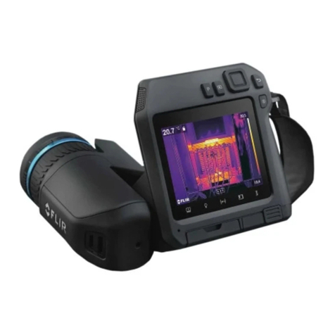
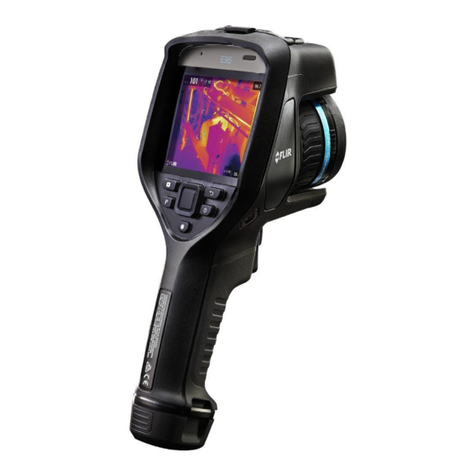
FLIR C Series User manual

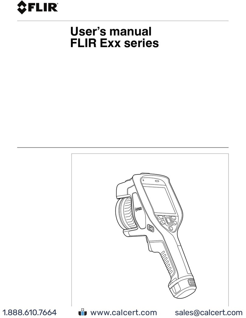
User’s manual
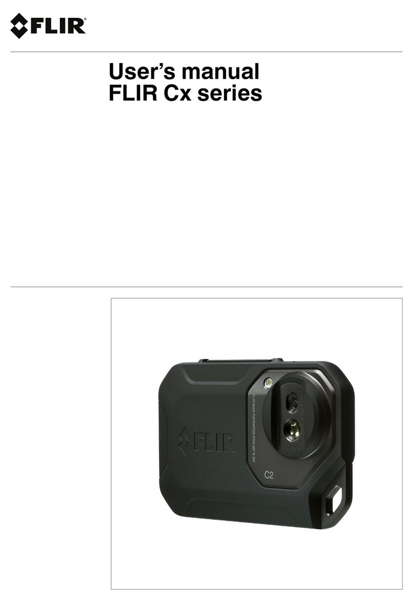
FLIR Cx series
Flir C2

Quick Start Guide
5
5.1 Procedure
Follow this procedure:
1. Charge the battery for approximately 1.5 hours, using the FLIR power supply.
2. Push the On/off button to turn on the camera.
3. Aim the camera toward your target of interest.
4. Push the Save button to save an image.
(Optional steps)
5. Download FLIR Tools from http://support.flir.com/tools.
6. Install FLIR Tools on your computer.
7. Start FLIR Tools.
8. Connect the camera to your computer, using the USB cable.
9. Import the images into FLIR Tools.
10. Create a PDF report in FLIR Tools.
#T559918; r. AN/42281/42281; en-US 11
With suggestions from Cambridge Carbon Fottprint
See Below
Connect Flir C2 to your PC via USB and switch on. When ON,
look for drive letter (eg D;) with Windows Explorer, etc.
Copy images from D:\DCIM\100_FLIR
Please delete your images from C2, when finished.

Description6
6.3 Connector
The purpose of this USB Micro-B connector is the following:
• Charging the battery using the FLIR power supply.
• Moving images from the camera to a computer for further analysis in FLIR Tools.
Note Install FLIR Tools on your computer before you move the images.
6.4 Screen elements
1. Main menu toolbar.
2. Submenu toolbar.
3. Result table.
4. Status icons.
5. Temperature scale.
6. Spotmeter.
6.5 Auto-orientation
The camera has an auto-orientation feature, which means that the camera automatically
adjusts the measurement information on the display to the vertical or horizontal position of
the camera.
#T559918; r. AN/42281/42281; en-US 13

Description6
Note The auto-orientation feature is enabled by a setting. Select Settings >Device set-
tings >Auto orientation >On.
6.6 Navigating the menu system
The camera has a touch screen. You can use your index finger or a stylus pen specially
designed for capacitive touch usage to navigate the menu system.
Tap the camera screen to bring up the menu system.
#T559918; r. AN/42281/42281; en-US 14

Operation
7
7.1 Charging the battery
WARNING
Make sure that you install the socket-outlet near the equipment and that it is easy to get access to.
Follow this procedure:
1. Connect the FLIR power supply to a wall outlet.
2. Connect the power supply cable to the USB connector on the camera.
7.2 Turning on and turning off the camera
• Push the On/off button to turn on the camera.
• Push and hold the On/off button until the screen goes off (for less than 5 sec-
onds) to put the camera in standby mode. The camera then automatically turns off after
2 hours.
• Push and hold the On/off button for more than 5 seconds to turn off the camera.
7.3 Saving an image
7.3.1 General
You can save images to the internal camera memory.
The camera saves both a thermal image and a visual image at the same time.
7.3.2 Image capacity
Approximately 500 images can be saved to the internal camera memory.
7.3.3 Naming convention
The naming convention for images is FLIRxxxx.jpg, where xxxx is a unique counter.
7.3.4 Procedure
Follow this procedure:
1. To save an image, push the Save button.
7.4 Recalling an image
7.4.1 General
When you save an image, it is stored in the internal camera memory. To display the image
again, you can recall it from the internal camera memory.
7.4.2 Procedure
Follow this procedure:
1. Tap the camera screen. This displays the main menu toolbar.
2. Select Images . This displays an image in the image archive.
#T559918; r. AN/42281/42281; en-US 15

Operation
7
3. To view the previous or next image, do one of the following:
• Swipe left or right.
• Tap the left arrow or the right arrow .
4. To switch between a thermal image and a visual image, swipe up or down.
5. Tap the camera screen. This displays a toolbar.
• Select Full screen or Exit full screen to switch between the full screen and
normal views.
• Select Thumbnails to display the thumbnail overview. To scroll between the
thumbnails, swipe up/down. To display an image, tap its thumbnail.
• Select Delete to delete the image.
• Select Information to display information about the image.
• Select Camera to return to live mode.
7.5 Deleting an image
7.5.1 General
You can delete an image from the internal camera memory.
7.5.2 Procedure
Follow this procedure:
1. Tap the camera screen. This displays the main menu toolbar.
2. Select Images . This displays an image in the image archive.
3. To display the previous or next image, do one of the following:
• Swipe left or right.
• Tap the left arrow or the right arrow .
4. When the image you want to delete is displayed, tap the camera screen. This displays
a toolbar.
5. On the toolbar, select Delete . This displays a dialog box.
6. In the dialog box, select Delete.
7. To return to live mode, tap the camera screen and select Camera .
7.6 Deleting all images
7.6.1 General
You can delete all images from the internal camera memory.
7.6.2 Procedure
Follow this procedure:
#T559918; r. AN/42281/42281; en-US 16
Please delete your images from C2, when finished.

Operation
7
1. Tap the camera screen. This displays the main menu toolbar.
2. Select Settings . This displays a dialog box.
3. In the dialog box, select Device settings. This displays a dialog box.
4. In the dialog box, select Reset options. This displays a dialog box.
5. In the dialog box, select Delete all saved images. This displays a dialog box.
6. In the dialog box, select Delete.
7. To return to live mode, tap the upper left arrow repeatedly. You can also push the
Save button once.
7.7 Measuring a temperature using a spotmeter
7.7.1 General
You can measure a temperature using a spotmeter. This will display the temperature at the
position of the spotmeter on the screen.
7.7.1.1 Procedure
Follow this procedure:
1. Tap the camera screen. This displays the main menu toolbar.
2. Select Measurement . This displays a submenu toolbar.
3. On the submenu toolbar, select Center spot .
The temperature at the position of the spotmeter will now be displayed in the top left
corner of the screen.
7.8 Hiding measurement tools
7.8.1 Procedure
Follow this procedure:
1. Tap the camera screen. This displays the main menu toolbar.
2. Select Measurement . This displays a submenu toolbar.
3. On the submenu toolbar, select No measurements .
7.9 Changing the color palette
7.9.1 General
You can change the color palette that the camera uses to display different temperatures. A
different palette can make it easier to analyze an image.
7.9.2 Procedure
Follow this procedure:
1. Tap the camera screen. This displays the main menu toolbar.
2. Select Color . This displays a submenu toolbar.
#T559918; r. AN/42281/42281; en-US 17

Operation
7
3. On the submenu toolbar, select the type of color palette:
•Iron.
•Rainbow.
•Rainbow HC.
•Gray.
7.10 Changing the image mode
7.10.1 General
The camera captures both thermal and visual images at the same time. By your choice of
image mode, you select which type of image to display on the screen.
The camera supports the following image modes:
•Thermal MSX (Multi Spectral Dynamic Imaging): The camera displays an infrared im-
age where the edges of the objects are enhanced with visual image details.
•Thermal: The camera displays a fully infrared image.
•Digital camera: The camera displays only the visual image captured by the digital
camera.
To display a good fusion image (Thermal MSX mode), the camera must make adjustments
to compensate for the small difference in position between the digital camera lens and the
#T559918; r. AN/42281/42281; en-US 18

Operation
7
infrared lens. To adjust the image accurately, the camera requires the alignment distance
(i.e., the distance to the object).
7.10.2 Procedure
Follow this procedure:
1. Tap the camera screen. This displays the main menu toolbar.
2. Select Image mode . This displays a submenu toolbar.
3. On the submenu toolbar, select one of the following:
•Thermal MSX .
•Thermal .
•Digital camera .
4. If you have selected the Thermal MSX mode, also set the distance to the object by
doing the following:
• On the submenu toolbar, select Alignment distance . This displays a dialog box.
• In the dialog box, select the distance to the object.
7.11 Changing the temperature scale mode
7.11.1 General
The camera can operate in two different temperature scale modes:
•Auto mode: In this mode, the camera is continuously auto-adjusted for the best image
brightness and contrast.
•Lock mode: In this mode, the camera locks the temperature span and the temperature
level.
7.11.2 When to use Lock mode
A typical situation where you would use Lock mode is when looking for temperature
anomalies in two items with a similar design or construction.
For example, you have two cables, and you suspect that one is overheated. With the cam-
era in Auto mode, direct the camera toward the cable that has a normal temperature, and
then activate Lock mode. When you then direct the camera, in Lock mode, toward the sus-
pected overheated cable, that cable will appear in a lighter color in the thermal image if its
temperature is higher than the first cable.
If you instead use Auto mode, the color for the two items might appear the same despite
their temperature being different.
7.11.3 Procedure
To go between Auto mode and Lock mode, tap the top or bottom temperature value in the
temperature scale.
A gray padlock icon indicates that Lock mode is active.
#T559918; r. AN/42281/42281; en-US 19
Also called 'Manual' Mode
Good for comaprisons or when temperature extremes in view
Simple, normally recommended
NB: look for a padlock icon, screen-right and touch a scale number to remove it,
if you want the simpler Auto mode.
Operation
7
7.12 Setting the emissivity
7.12.1 General
To measure temperatures accurately, the camera must be aware of the type of surface you
are measuring. You can choose between the following surface properties:
•Matt.
•Semi-matt.
•Semi-glossy.
As an alternative, you can set a custom emissivity value.
For more information about emissivity, see section 15 Thermographic measurement tech-
niques, page 59.
7.12.2 Procedure
Follow this procedure:
1. Tap the camera screen. This displays the main menu toolbar.
2. Select Settings . This displays a dialog box.
3. In the dialog box, select Measurement parameters. This displays a dialog box.
4. In the dialog box, select Emissivity. This displays a dialog box.
5. In the dialog box, select one of the following:
•Matt.
•Semi-matt.
•Semi-glossy.
•Custom value. This displays a dialog box where you can set a value.
6. To return to live mode, tap the upper left arrow repeatedly. You can also push the
Save button once.
7.13 Changing the reflected apparent
temperature
7.13.1 General
This parameter is used to compensate for the radiation reflected by the object. If the emis-
sivity is low and the object temperature significantly different from that of the reflected tem-
perature, it will be important to set and compensate for the reflected apparent temperature
correctly.
For more information about the reflected apparent temperature, see section 15 Thermo-
graphic measurement techniques, page 59.
7.13.2 Procedure
Follow this procedure:
1. Tap the camera screen. This displays the main menu toolbar.
2. Select Settings . This displays a dialog box.
3. In the dialog box, select Measurement parameters. This displays a dialog box.
4. In the dialog box, select Reflected temperature. This displays a dialog box where you
can set a value.
#T559918; r. AN/42281/42281; en-US 20
Shiny metals and glass have low emissivities, giving wrong temperatires
It's hard to compansate for low emissivities. Advanced only
Advanced Only

Operation
7
5. To return to live mode, tap the upper left arrow repeatedly. You can also push the
Save button once.
7.14 Changing the distance
7.14.1 General
The distance is the distance between the object and the front lens of the camera. This pa-
rameter is used to compensate for the following two facts:
• That radiation from the target is absorbed by the atmosphere between the object and
the camera.
• That radiation from the atmosphere itself is detected by the camera.
For more information, see section 15 Thermographic measurement techniques, page 59.
7.14.2 Procedure
Follow this procedure:
1. Tap the camera screen. This displays the main menu toolbar.
2. Select Settings . This displays a dialog box.
3. In the dialog box, select Measurement parameters. This displays a dialog box.
4. In the dialog box, select Distance. This displays a dialog box where you can set a
value.
5. To return to live mode, tap the upper left arrow repeatedly. You can also push the
Save button once.
7.15 Performing a non-uniformity correction
7.15.1 What is a non-uniformity correction?
A non-uniformity correction (or NUC) is an image correction carried out by the camera
software to compensate for different sensitivities of detector elements and other optical
and geometrical disturbances1.
7.15.2 When to perform a non-uniformity correction
The non-uniformity correction process should be carried out whenever the output image
becomes spatially noisy. The output can become spatially noisy when the ambient temper-
ature changes (such as from indoors to outdoors operation, and vice versa).
7.15.3 Procedure
To perform a non-uniformity correction, tap and hold the icon. The text Calibrating...
appears on the screen.
#T559918; r. AN/42281/42281; en-US 21
1. Definition from the imminent international adoption of DIN 54190-3 (Non-destructive testing – Thermographic
testing – Part 3: Terms and definitions).
Advanced Only
Normally occurs automatically

Operation
7
7.16 Using the camera lamp
7.16.1 General
You can use the camera lamp as a flashlight, or as a flash when taking an image.
7.16.2 Procedure
Follow this procedure:
1. Tap the camera screen. This displays the main menu toolbar.
2. Select Lamp .
3. Tap one of the following:
•Flash (to use the lamp as a flash when taking an image).
•On (to turn on the lamp and use it as a flashlight).
•Off (to turn off the lamp).
7.17 Configuring Wi-Fi
Depending on your camera configuration, you can connect the camera to a wireless local
area network (WLAN) using Wi-Fi, or let the camera provide Wi-Fi access to another
device.
You can connect the camera in two different ways:
•Most common use: Setting up a peer-to-peer connection (also called an ad hoc or P2P
connection). This method is primarily used with other devices, e.g., an iPhone or iPad.
•Less common use: Connecting the camera to a WLAN.
7.17.1 Setting up a peer-to-peer connection (most common use)
Follow this procedure:
1. Tap the camera screen. This displays the main menu toolbar.
2. Select Settings . This displays a dialog box.
3. Select Device settings.
4. Select Wi-Fi.
5. Select Share.
6. (Optional step.) To display and change the parameters, select Settings.
• To change the channel (the channel that the camera is broadcasting on), select
Channel.
• To activate WEP (encryption algorithm), select WEP. This will check the WEP check
box.
• To change the WEP password, select Password.
Note These parameters are set for your camera’s network. They will be used by the
external device to connect that device to the network.
7.17.2 Connecting the camera to a wireless local area network (less common
use)
Follow this procedure:
1. Tap the camera screen. This displays the main menu toolbar.
2. Select Settings . This displays a dialog box.
#T559918; r. AN/42281/42281; en-US 22
Not available with C2

Operation
7
3. Select Device settings.
4. Select Wi-Fi.
5. Select Connect to network.
6. To display a list of the available networks, select Networks.
7. Select one of the available networks.
Password-protected networks are indicated with a padlock icon, and for these you will
need to enter a password.
Note Some networks do not broadcast their existence. To connect to such a network,
select Add network... and set all parameters manually according to that network.
7.18 Changing the settings
7.18.1 General
You can change a variety of settings for the camera.
The Settings menu includes the following:
•Measurement parameters.
•Save options.
•Device settings.
7.18.1.1 Measurement parameters
•Emissivity.
•Reflected temperature.
•Distance.
7.18.1.2 Save options
•Photo as separate JPEG: When this menu command is selected, the digital photograph
from the visual camera is saved at its full field of view as a separate JPEG image. It
may be necessary to activate this option if you are not using the FLIR Tools software.
7.18.1.3 Device settings
•Language, time & units:
◦Language.
◦Temperature unit.
◦Distance unit.
◦Date & time.
◦Date & time format.
•Reset options:
◦Reset default camera mode.
◦Reset device settings to factory default.
◦Delete all saved images.
•Auto power off.
•Auto orientation.
•Display intensity.
•Camera information: This menu command displays various items of information about
the camera, such as the model, serial number, and software version.
7.18.2 Procedure
Follow this procedure:
#T559918; r. AN/42281/42281; en-US 23
Suggested Settings
DD/MM/YY
Try this if PC cpmms via USB fails
5 min
Med
Type text here
Please delete your images from C2, when finished.
0.95
20°C
5m

Operation
7
1. Tap the camera screen. This displays the main menu toolbar.
2. Select Settings . This displays a dialog box.
3. In the dialog box, tap the setting that you want to change.
4. To return to live mode, tap the upper left arrow repeatedly. You can also push the
Save button once.
7.19 Updating the camera
7.19.1 General
To take advantage of our latest camera firmware, it is important that you keep your camera
updated. You update your camera using FLIR Tools.
7.19.2 Procedure
Follow this procedure:
1. Start FLIR Tools.
2. Start the camera.
3. Connect the camera to the computer using the USB cable.
4. FLIR Tools displays a welcome screen when the camera is identified. On the welcome
screen, click Check for updates.
You can also click Check for updates on the Help menu in FLIR Tools.
5. Follow the on-screen instructions.
#T559918; r. AN/42281/42281; en-US 24
Please don't try this

last page
Publ. No.: T559918
Release: AN
Commit: 42281
Head: 42281
Language: en-US
Modified: 2017-04-27
Formatted: 2017-05-02
Website
http://www.flir.com
Customer support
http://support.flir.com
Copyright
© 2017, FLIR Systems, Inc. All rights reserved worldwide.
Disclaimer
Specifications subject to change without further notice. Models and accessories subject to regional market considerations. License procedures may apply. Products
described herein may be subject to US Export Regulations. Please refer to exportquestions@flir.com with any questions.
Other manuals for C Series
3
This manual suits for next models
1
Table of contents
Other FLIR Thermal Camera manuals

FLIR
FLIR ONE PRO LT User manual

FLIR
FLIR PatrolIR PTZ User manual

FLIR
FLIR AX Series User manual

FLIR
FLIR ONE Edge Series User manual

FLIR
FLIR TG267 User manual

FLIR
FLIR HM-Series User manual

FLIR
FLIR X8400sc User manual

FLIR
FLIR MV series Installation and operating instructions

FLIR
FLIR PathFindIR User manual

FLIR
FLIR Duo Pro R User manual