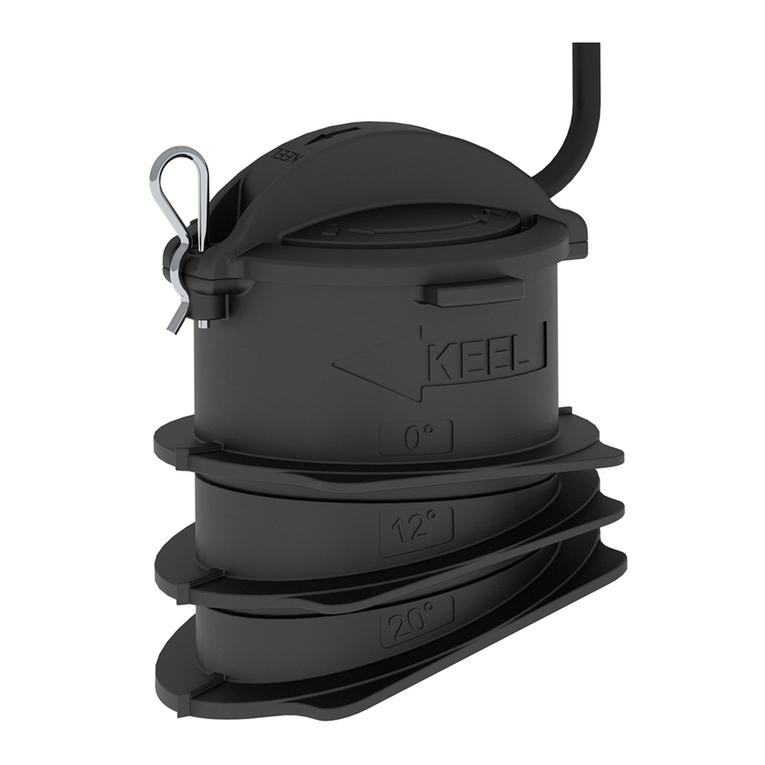
FLIR Raymarine CPT-90DVS User manual

CPT-90DVS/CPT-100DVS
Installationinstructions
Warning:Productinstallationand
operation
•Thisproductmustbeinstalledandoperatedin
accordancewiththeinstructionsprovided.Failure
todosocouldresultinpersonalinjury,damageto
yourvesseland/orpoorproductperformance.
•Raymarinerecommendscertiedinstallation
byaRaymarineapprovedinstaller.Acertied
installationqualiesforenhancedproduct
warrantybenets.ContactyourRaymarinedealer
forfurtherdetails,andrefertotheseparate
warrantydocumentpackedwithyourproduct.
Warning:Highvoltages
Thisproductmaycontainhighvoltages.DoNOT
removeanycoversorotherwiseattempttoaccess
internalcomponents,unlessspecicallyinstructed
inthedocumentationprovided.
Warning:Switchoffpowersupply
Ensurethevessel’spowersupplyisswitchedOFF
beforestartingtoinstallthisproduct.DoNOT
connectordisconnectequipmentwiththepower
switchedon,unlessinstructedinthisdocument.
Caution:Serviceandmaintenance
Thisproductcontainsnouserserviceable
components.Pleasereferallmaintenance
andrepairtoauthorizedRaymarinedealers.
Unauthorizedrepairmayaffectyourwarranty.
Caution:Transducercable
•DoNOTusethetransducercabletoliftor
suspendthetransducer;alwayssupportthe
transducerbodydirectlyduringinstallation.
•DoNOTcut,shorten,orsplicethetransducer
cable.
•DoNOTremovetheconnector.
Ifthecableiscut,itcannotberepaired.Cutting
thecablewillalsovoidthewarranty.
Caution:Productcleaning
Whencleaningproducts:
•Lightlyrinseorushwithclean,coolfresh
water.
•Ifyourproducthasadisplayscreen,doNOT
wipethescreenwithadrycloth,asthiscould
scratchthescreencoating.
•DoNOTuse:abrasive,acidic,ammonia,
solventofchemicalbasedcleaningproducts.
•DoNOTuseajetwash.
Partssupplied
1.Mountingbracket
2.Ratchetarm
3.M5Hexratchetbolt
4.Ratchetplate
5.Compressionwasher
6.M5washer
7.M5lockingnut
8.*Escutcheon(forthrough-transomcablerouting),plus2
screws
9.*P-clipsand3screws
10.Documentation
11.Transducerwithcable
Note:*NOTsuppliedwithCPT-90DVSvariant.
Selectingalocationforthetransducer
Thisproductissuppliedwithatransommounttransducer.The
guidelinesbelowshouldbefollowedwhenselectingalocation
forthetransducer.
Note:Thetransducerisnotsuitableformountingonvessels
wherethetransomisaftofthepropeller(s).
Forbestperformancethetransducermustbeinstalledina
locationwiththeleastturbulenceandaeration.Themosteffective
waytodeterminethisisbycheckingthewaterowaroundthe
transomwhilstunderway.
•Mountclosetothekeel(centerline),inapositionwherethe
transducerelementwillbefullysubmergedwhenthevessel
isplaningandturning.
•Mountasuitabledistancefromthepropeller(s)toavoidwake.
•Forclockwiserotatingpropellers,mountthetransduceronthe
starboardside,forcounter-clockwise,mountontheportside.
•Onatwinenginevesselmountthetransducerbetweenthe
engines.
•Turbulencecanbecausedbyanumberofotherfactorssuch
assteps(1),ribs(2),rowsofrivets(3)andstrakes(4).The
turbulenceappearsaftoftheselocations.
Documentnumber:88065-2AA;3945;2017-05-11T09:30:39Date:05-2017

•Airtrappedunderthefrontofthevesselcantravelunderthe
hullandappearasaerationaft.
•Ifinstallingonthestepofasteppedtransom,allowsufcient
roomabovethetransducerfortransducerkickup.
Note:Optimumtransducerlocationwillvarydependingon
vesseltype.Optimumtransducerheightandangleshould
beobtainedbytestingthetransducerwiththevesselin
thewater.
Productdimensions–CPT-DV/CPT-DVS/
CPT-100DVS/CPT-90DVS
Thetransducer’sdimensionsincludingthetransommounting
bracketareshownbelow.
•TheCPT-DVcablelengthis4m(13.1ft.)
•TheCPT-DVScablelengthis6m(19.7ft.)
•TheCPT-90DVScablelengthis6m(19.7ft.)
•TheCPT-100DVScablelengthis10m(32.8ft.)
Cablerouting
Cableroutingrequirementsforthetransducercable.
Important:Toavoidinterference,thecablemustberoutedas
farawayfromVHFradioantennacablesaspossible.
•Thecablecanberoutedthroughoroverthetransom.
•Checkthatthecableislongenoughtoreachtheequipment
thatitwillbeconnectedto.Anoptional4m(13.1ft)extension
cableisavailableifrequired.
•Ensurethereisenoughslackinthetransducercable,atthe
transducerend,toallowthetransducertopivotupanddown.
•Securethecableatregularintervalsusingcableclips.Please
note,cableclipsarenotsuppliedwithalltransducervariants.
•Fillalltransommountingholeswithmarine-gradeneutralcure
polyurethanesealantpriortotighteningsecuringscrews.
•Fillthetransomcableholewithmarine-gradeneutralcure
polyurethanesealantafterroutingthecable(ifroutingthrough
thetransom).
•Useanescutcheontocoveroverthetransomcablehole(if
routingthroughthetransom).Pleasenote,anescutcheonis
notsuppliedwithalltransducervariants.
•Anyexcesscablecanbecoiledupataconvenientlocation.
Note:DoNOTusesealantscontainingacetateorsilicone,
whichcancausedamagetoplasticparts.
Maximumtransducercablelength
Themaximumrecommendedcablelengthfromthetransducerto
theunitisshownbelow.
CPT-DV8m(26.2ft.)—4m(13.1ft.)
suppliedcable+4m(13.1ft.)
extensioncable
CPT-DVS10m(32.8ft.)—6m(19.7ft.)
suppliedcable+4m(13.1ft.)
extensioncable
CPT-90DVS10m(32.8ft.)—6m(19.7ft.)
suppliedcable+4m(13.1ft.)
extensioncable
CPT-100DVS14m(45.9ft.)—10m(32.8ft.)
suppliedcable+4m(13.1ft.)
extensioncable
Note:Extendingthetransducercablebeyondthemaximum
statedlengthwillcausepoorperformance.
Mountingthetransommountbracket
Thetransducermustbemountedonthetransomusingthe
mountingbracketprovided.Thestepsbelowdescribethe
initialmountingstepsrequiredinordertotestyourtransducers
performance.Aftertestingthetransduceryoumustnishthe
mountingfollowingtheinstructionsintheFinishingthetransducer
mountingsection.
1.Fixthetransducermountingtemplatetotheselectedlocation,
usingmaskingorself-adhesivetape.
1Transducermountingtemplate
2Waterline
3Mountingawayfrompropeller
2.Ensurethetemplateisparalleltothewaterline.
3.Drill2xholesfortheadjustmentslotscrewsasindicatedon
thetemplate.
Note:DoNOTdrillthethirdmountingholeatthisstage.
2CPT-90DVS/CPT-100DVSInstallationinstructions

4.Fillthe2holeswithmarinegradesealant.
5.Usingapozi-drivescrewdriverandthescrewsprovided,
securethetransommountbracketusingthe2adjustment
slots.
Note:Thethirdlockingscrewisnotuseduntilthetransducer
hasbeensuccessfullytested.
Mountingthetransducer
Thetransducermustbemountedonthetransomusingthe
mountingbracketprovided.Thestepsbelowdescribethe
initialmountingstepsrequiredinordertotestyourtransducers
performance.Aftertestingthetransduceryoumustnishthe
mountingfollowingtheinstructionsintheFinishingthetransducer
mountingsection.
1.Feedthetransducercablebetweenthepostsonthemounting
bracketasshown.
2.Slidetheratchetarmintotheguideonthetopofthe
transducer,ensuringitlocksinplace.
3.Holdtheratchetplateinplaceontheratchetarmasshown.
4.Inserttheratchetarmbetweenthemountingbracketposts,
aligningthecenterholewiththeholesintheposts.
5.SlidetheM5washerandthenthecompressionwasheronto
theratchetbolt.
6.Slidetheratchetboltthroughthemountingbracketassembly.
7.InserttheM5lockingnutintothecaptivehousingonthe
mountingbracket.
8.Usinga4mmHexwrench(allenkey)tightentheratchet
boltuntiltheratchetmechanismisengagedbutcanstillbe
adjustedbyhand.
9.Positionthetransducersothatthebottomfaceofthe
transducerwillbeparallelwiththewaterlineandtightenthe
ratchetbolt.
Thetransducerpositionwillbeadjustedfurtherduringtesting.
Testingandadjustingthetransducer
Oncetheinitialmountingprocedureshavebeencarriedout,the
transducermustbetestedpriortonishingthemounting.
Thetestingshouldbecarriedoutwithyourvesselinthewater,
withadepthgreaterthan0.7m(2.3ft)butlessthanthemaximum
depthrangeofthetransducer.
Important:TheSonarchannelwillbeabletomaintain
readingsathighervesselspeedsandatgreaterdepthsthan
theDownVision™application.
1.PressandholdthePowerbuttontopowertheuniton.
2.CompletetheStart-upwizardandtutorial.
3.Opentherelevantapplication.
Thebottomshouldbevisibleonscreenandadepthreading
displayed.
4.Startmovingyourvesselatalowspeed,ensuringyouhavea
depthreadingandaclearimageisdisplayed.
5.Graduallyincreasethevesselspeedwhilstcheckingthe
display,iftheimagebecomespoororthebottomismissingat
lowerspeedsthenthetransducerneedstobeadjusted.
6.Angleandheightadjustmentsshouldbemadeinsmall
incrementsandre-testedeachtimeuntilyouobtainoptimum
performance.
7.Loosentheratchetarmbolttoadjustthetransducerangle.
8.Loosenthe2mountingbracketscrewstoadjustthetransducer
height.
9.Re-tightentheratchetarmboltandmountingscrewsbefore
re-testing.
Note:
•Itmaynotalwaysbepossibletoobtaindepthreadings
athigherspeedsduetoairbubblespassingunderthe
transducer.
•Itmaybenecessarytomakeseveraladjustmentstothe
transducerbeforeobtainingoptimumperformance.
•Ifthetransducerrequiresrepositioningensurealloldholes
arelledwithmarinegradesealant.
Removingthetransducer
Thetransducercanbereleasedfromthebracketbyinsertinga
smallmetalrodsuchasapaperclipintothetransducerrelease
holelocatedasshown.
CPT-90DVS/CPT-100DVSInstallationinstructions3

1.Insertthemetalrodintothetransducerreleasehole.
2.Slidethetransduceroffofthebracket.
Finalizingthetransducermounting
Onceyouhaveachievedoptimumperformanceatthedesired
vesselspeedsthetransducermustbelockedintopositionto
completetheinstallation.
1.Drillthelockingholelocationtakingcarenottodamagethe
mountingbracket.
2.Fillthelockingholewithmarinegradesealant.
3.Securethetransducerandbracketbyfullytighteningall3
mountingscrews.
4.Securetheratchetarmbolt,bytighteninguntilthe
compressionwasheriscompressedandthenaddanother1/4
turn.Ifthetransducerkicksupatspeedthentightenfurther.
Important:Takecaretoensurethatthepivotboltisnot
overtightenedasthiswillpreventkick-upandmaycause
damage.
4CPT-90DVS/CPT-100DVSInstallationinstructions
This manual suits for next models
1
Other FLIR Transducer manuals
Popular Transducer manuals by other brands

Zemic
Zemic Atex instruction manual

Mianyang Weibo Electronic
Mianyang Weibo Electronic WBV332S01 user manual

Kanomax
Kanomax 6333 user manual

Airmar
Airmar B60 installation instructions

TR-Electronic
TR-Electronic LA Series Assembly instructions

Dwyer Instruments
Dwyer Instruments WWDP Series Installation and operating instructions

Endress+Hauser
Endress+Hauser Levelflex FMP53 installation instructions

Balluff
Balluff BTL6-V11V-M Series user guide

Johnson Outdoors
Johnson Outdoors Cannon Digi-Troll IV manual

TR-Electronic
TR-Electronic LMRI-46H 605 SSI manual

KEPO
KEPO KPT-1420A specification

Clark Synthesis
Clark Synthesis TST329 specification