manuals.online logo
Brands
  1. Home
  2. •
  3. Brands
  4. •
  5. NK TECHNOLOGIES
  6. •
  7. Transducer
  8. •
  9. NK TECHNOLOGIES DT Series User manual

NK TECHNOLOGIES DT Series User manual

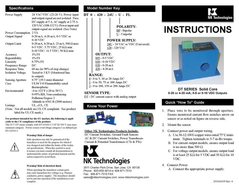
INSTRUCTIONS
1. Place wire to be monitored through aperture.
Ensure monitored current flow matches arrow
on sensor or as noted on figure on reverse
side.
2. Mount the sensor.
3. Connect power and output wiring.
A. Use 22-14 AWG copper wires rated 75°C
minimum. Tighten terminals to 5 in-lbs (.6
Nm) torque.
B. For current output models, ensure output
load is no more than 500 Ω.
C. For voltage output models, ensure output
load is at least 10KΩ.
4. Connect Power.
A. Connect the appropriate power supply.
DT 0 - 420 - 24U - U - FL
OUTPUT:
005- 0-5 VDC
010- 0-10 VDC
020- 0-20 mA
420- 4-20 mA
RANGE
0- 0 to 5, 10 or 20 Amps DC
1- 0 to 50, 75 or 100 Amps DC
2- 0 to 100, 150 or 200 Amps DC
Model Number KeySpecifications
Quick “How To” Guide
POWER SUPPLY:
24U- 24 VAC or VDC (Universal)
120- 120 VAC
Output Signal 0-20mA, 4-20mA, 0-5VDC or
0-10VDC
Accuracy 1% FS
Frequency Range DC
Isolation Voltage 3kV (Monitored line to output)
Linearity 0.75% FS
Response Time 160 mS (to 90% of step change)
Repeatability 1% FS
Power Supply
24VAC/DC Option: Power inputand output signal are not
isolated. Fuse DC supply at 5 amps,
AC supply at 2.75 amps.
120VAC Option: Power input and output signal are
isolated.
Power Consumption 2 VA
Enclosure UL 94V-0 Flammability rated
thermoplastic
Environmental -4 to +122 F (-20 to 50 degree C)
0-95% RH non-condensing
Pollution Degree 2
Altitude to 2000 meters
Approvals UL, cUL, CE (Note: Not all models
are CE compliant. See product label
for CE mark)
3511 Charter Park Drive, San Jose, CA 95136
800-959-4014 or +1-408-871-7510 Phone
+1-408-871-7515 FAX
[email protected], www.nktechnologies.com
Know Your Power
Other NK Technologies Products Include:
DC Current Switches, Ground Fault Sensors
AC & DC Current Switches, Power Transducers
Current & Potential Transformers (CTs&PTs)
POLARITY:
BP- Bipolar
U- Unipolar
DT SERIES Solid Core
0-20 or 4-20mA; 0-5 or 0-10 VDC Outputs
SENSOR TYPE:
DT - DC current sensor with analog output.
Instr. Sheet DT-FL p/n 291004109 rev 3 04/16
For products intended for the EU market, the following is
applicable to the CE compliance of the product:
The DT series comply with EN 61010-1 CAT III 600V max
measurement category. Use 24 V input power and fuse at 5
amps. Power source overvoltage category I as defined per EN
61010-1.
Caution! Risk of danger
Safe operation can only be guaranteed if the
transducer is used for the purpose for which it was
designed and within the limits of the technical
specifications When this symbol is used, it means
you must consult all documentation to understand
the nature of potential hazards and the action
required to avoid them.
Caution! Risk of electrical shock
When operating the transducer certain parts
may carry hazardous live voltage (e.g. Primary
conductor, power supply). The transducer should
not be put into operation if the installation is not
complete.
Place wire to be monitored through sensor aperture. Care
should be taken to ensure current flow is in accordance with
any directional arrows on sensor and as noted in the figure,
above right.
DT Series transducers work in the same environment as
motors, contactors, heaters, pull-boxes, and other electrical
enclosures. They can be mounted in any position or hung
directly on wires with a wire tie. For optimal performance,
ensure unit has been energized for a period of 20 minutes
prior to sensing operation.
Description
Installation
Wiring & Mounting Information
Range Select
DT Series transducers feature factory calibrated, field
selectable ranges.
1. Determine the normal operating amperage of moni-
tored circuit
1. Output Signal Too Low
A. The jumper may be set in a range that is too high for
current being monitored. Move jumper to the correct
range.
B. Power supply is inadequate. Check power supply.
Make sure it is of sufficient voltage with all loads at
maximum. DT Series consumes 2.0 VA.
C. Output load too high. Check output load, be sure it
is no more than 500 Ωfor mAoutput, more than 10K
Ω for VDC output.
2. Output Signal is always at maximum
A. The jumper may be set in a range that is too low for
current being monitored. Move jumper to the correct
range.
3. Sensor has no output
A. Polarity is not properly matched. Check and correct
wiring polarity.
B. Monitored load is not DC or is not on. Check that
the monitored load is DC and that it is actually on.
Trouble Shooting
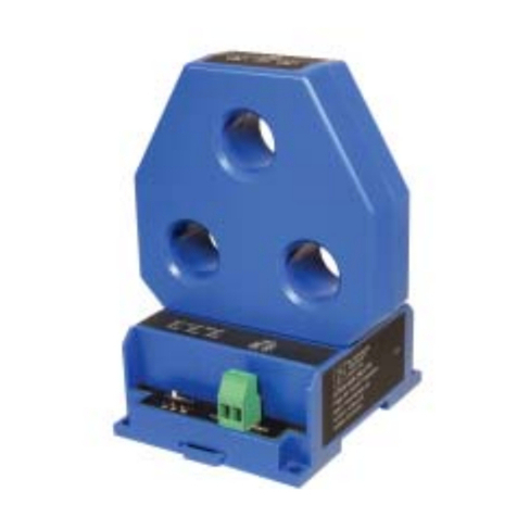
DT Series transducers combine a Hall Effect sensor and
a signal conditioner into a single package. This provides
higher accuracy, lower wiring costs, easier installation
and saves valuable panel space. DT Series are available
with 0-20 mA, 4-20mA, 0-5VDC or 0-10VDC outputs.
2. Select the range that is equal to or slightly higher than
the normal operating amperage.
3. Place the range jumper in the appropriate position.
Unipolar versus Bipolar Output
0-20mA & 4-20mA:
The current loop is powered by the DT Transducer.
Maximum loop impedance is 500 Ω.
0-5VDC & 0-10 VDC:
Signal is powered by the DT Transducer. Minimum out-
put load (impedance) is 10K Ω.
Current Direction:
Ensure the direction of monitored current is the same as
the direction shown on the diagram. The unit will not
operate properly if the current is opposite the direction of
the arrow.
1 2 3 4
Power - +
Output Signal
Range
Selection
Unipolar Bipolar
+
-Note: Unipolar transducers produce an output signal
with current flowing in one direction only. Bipolar trans-
ducers produce an output with current flowing in both
directions through the sensor.
FS
0
4
20
Output (mA)
Range
Unipolar Output
+FS
-FS
(4mA, 0VDC) 0%
(20mA, 5 or 10VDC)100%
Output (percentage of full scale)
Current Range
Bipolar Output
0
(12mA, 2.5 or 5VDC)50%

Other NK TECHNOLOGIES Transducer manuals

NK TECHNOLOGIES DTC 2-420-24U-FL User manual

NK TECHNOLOGIES

NK TECHNOLOGIES DTC 2-420-24U-FL User manual

NK TECHNOLOGIES AT 2 Series User manual

NK TECHNOLOGIES

NK TECHNOLOGIES AT 2 Series User manual

NK TECHNOLOGIES APS Series User manual

NK TECHNOLOGIES

NK TECHNOLOGIES APS Series User manual

NK TECHNOLOGIES VTD-BD Series User manual

NK TECHNOLOGIES

NK TECHNOLOGIES VTD-BD Series User manual

NK TECHNOLOGIES DT Series User manual

NK TECHNOLOGIES

NK TECHNOLOGIES DT Series User manual

NK TECHNOLOGIES AT-TH Series User manual

NK TECHNOLOGIES

NK TECHNOLOGIES AT-TH Series User manual

NK TECHNOLOGIES VTU Series User manual

NK TECHNOLOGIES

NK TECHNOLOGIES VTU Series User manual

NK TECHNOLOGIES VTD Series User manual

NK TECHNOLOGIES

NK TECHNOLOGIES VTD Series User manual

NK TECHNOLOGIES APS Series User manual

NK TECHNOLOGIES

NK TECHNOLOGIES APS Series User manual

NK TECHNOLOGIES VTU Series User manual

NK TECHNOLOGIES

NK TECHNOLOGIES VTU Series User manual

NK TECHNOLOGIES AT SERIES User manual

NK TECHNOLOGIES

NK TECHNOLOGIES AT SERIES User manual

NK TECHNOLOGIES VTR Series User manual

NK TECHNOLOGIES

NK TECHNOLOGIES VTR Series User manual

NK TECHNOLOGIES ATQ Series User manual

NK TECHNOLOGIES

NK TECHNOLOGIES ATQ Series User manual

Popular Transducer manuals by other brands

Siemens 7XV5653-0BA00 operating instructions

Siemens

Siemens 7XV5653-0BA00 operating instructions

Mindray P8-2TU Operator's manual

Mindray

Mindray P8-2TU Operator's manual

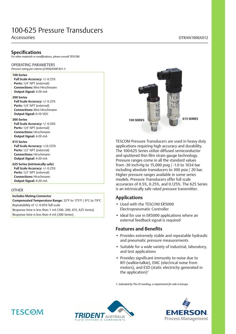
Tescom 100 Series manual

Tescom

Tescom 100 Series manual

Balluff BTL5-S1 Series user guide

Balluff

Balluff BTL5-S1 Series user guide

Lumel P18S user manual

Lumel

Lumel P18S user manual

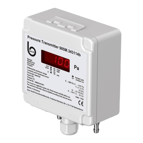
Beck 985A manual

Beck

Beck 985A manual

Lumel P20 user manual

Lumel

Lumel P20 user manual

Airmar Depth & Temperature P66 Owner's guide & installation instructions

Airmar

Airmar Depth & Temperature P66 Owner's guide & installation instructions

S+S Regeltechnik AERASGARD KLQ-W Series Operating Instructions, Mounting & Installation

S+S Regeltechnik

S+S Regeltechnik AERASGARD KLQ-W Series Operating Instructions, Mounting & Installation

Mercoid SBLTX Series Installation and operating instructions

Mercoid

Mercoid SBLTX Series Installation and operating instructions

JPS JUPITER-STD user manual

JPS

JPS JUPITER-STD user manual

Balluff BTL5-P user guide

Balluff

Balluff BTL5-P user guide

Iskra MT416 user manual

Iskra

Iskra MT416 user manual

MG 18PF instruction manual

MG

MG 18PF instruction manual

Setra Systems 209 installation guide

Setra Systems

Setra Systems 209 installation guide

Deif MTR-3 installation instructions

Deif

Deif MTR-3 installation instructions

HBK AED 9101D operating manual

HBK

HBK AED 9101D operating manual

Garmin gWind Race installation instructions

Garmin

Garmin gWind Race installation instructions

manuals.online logo
manuals.online logoBrands
  • About & Mission
  • Contact us
  • Privacy Policy
  • Terms and Conditions

Copyright 2025 Manuals.Online. All Rights Reserved.