Lumel P18S User manual

1
TEMPERATURE
AND HUMIDITY TRANSDUCER
P18S
USER’S MANUAL

2

3
Contents
1. APPLICATION............................................................................... 5
2. TRANSDUCER SET ..................................................................... 6
3. BASIC REQUIREMENTS, OPERATIONAL SAFETY..................... 6
4. ASSEMBLY................................................................................... 6
4.1. INSTALLATION....................................................................... 6
4.2. EXTERNAL CONNECTIONS DIAGRAM ............................... 8
5. OPERATION ................................................................................. 9
5.1. TRANSDUCER FUNCTIONS............................................... 10
5.1.1. CALCULATED VALUES .................................................... 10
5.1.2. OPERATION OF THE INTERNAL HEATER...................... 12
5.1.3. SERIAL INTERFACE CONNECTION METHOD ................... 12
5.1.4. DESCRIPTION OF MODBUS PROTOCOL IMPLEMENTATION... 13
5.1.5. DESCRIPTION OF IMPLEMENTED FUNCTIONS ........... 14
5.1.6. MAP OF REGISTERS ....................................................... 15
5.1.7. READ-ONLY REGISTERS ............................................. 16
5.1.8. REGISTERS FOR WRITING AND READING ................. 17
6. ACCESSORIES .......................................................................... 21
7. TECHNICAL DATA ..................................................................... 22
8. ORDERING CODE...................................................................... 23

4

5
1. APPLICATION
The P18S transducer is designed for continuous measure-
ment and conversion of relative humidity and ambient temperature into
a digital form (MODBUS RTU protocol via the RS-485 interface). Trans-
ducer configuration is possible using the MODBUS protocol.
Values measured and calculated by the transducer:
• temperature,
• relative humidity
• dew point
• absolute humidity
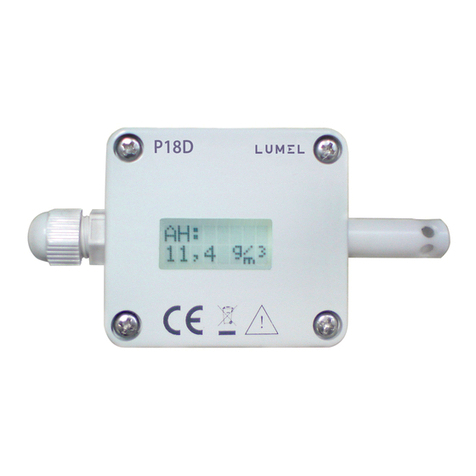
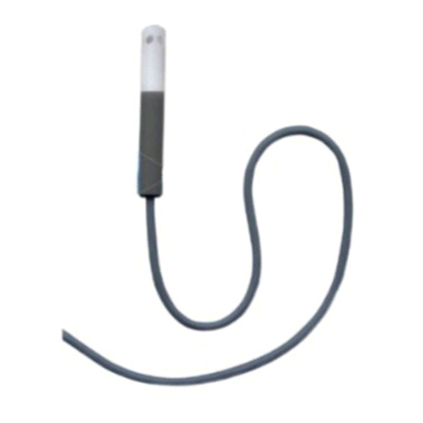
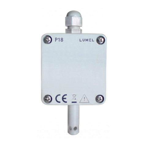
Fig.1. View of P18S transducer.

6
2. TRANSDUCER SET
−P18S transducer 1 pc.
−User’s manual 1 pc.
3. BASIC REQUIREMENTS,
OPERATIONAL SAFETY
In terms of operational safety, the transducer meets the requi-
rements of EN 61010-1 standard.
4. ASSENBLY
4.1. Installation
The transducer should be mounted in a safe manner using ge-
nerally available assembly elements, such as cable glands and cable grom-
mets, clamps, cable ties enabling access when service works are needed
(e.g. cleaning in the event of soiling affecting the device operation, replace-
ment in the case of damage). It is important to ensure the transducer wor-
king position so that its measuring sensor is directed downwards. Electrical
connections should be made in accordance with the transducer connection
diagram.
Safety instructions
• The assembly and the installation of the electrical connections may
be carried out only by a duly qualified electrician.
• Before turning the transducer on verify the connections.
• The transducer is intended for installation and use in industrial electro-
magnetic environments.

7
Fig.2. External dimensions of P18S
min. 50mm
R20
83
12

8
4.2. External connections diagram
The transducer has a 4-wire non-detachable cord which is 2.5 or 10m
long or a detachable M8 socket with a 2-meter long wire (depending on
the version code) used for supplying and connecting the RS-485 inter-
face:
Table 1: Transducer terminals
non-detachable cord
(color of the cord)
M8 socket
(terminal number)
cable with M8 plug
(color of the cord)) Function
green 3 blue Positive power cordVCC
yellow 1 brown Negative power cord GND
brown 4 black RS-485 “B”signal
white 2 white RS-485“A”signal

9
5. OPERATION
After wiring and turning on the power supply, the transducer is
ready for operation with the factory settings. Operation of the transducer
is signaled by a short, repeatable illumination of the yellow LED located
under the sensor cover.
The transducer can be configured by recording MODBUS RTU pro-
tocol registers on the RS-485 interface.
The following parameters can be programmed in the transducer:
−device address for MODBUS RTU protocol
−RS-485 interface baud rate
−RS-485 interface communication mode
−measurements averaging mode
−erasing the saved values of extreme measurements
−switching on/off the internal heater
−setting the heating time with the internal heater in time mode
−fixed correction for temperature measurement
Through dedicated registers, it is also possible to restore the trans-
ducer factory parameters and force the recording of current operating
parameters into the non-volatile memory of the transducer.
CAUTION: In case when unknown transmission parameters are set
in the transducer, it is possible to force the transducer communication
according to the standard parameters (9600, 8N1). To do this:
−turn off the transducer power supply
−remove the sensor cover
−short together the soldering points in accordance with figure 2
−turn on the transducer power supply (the LED will be solid yellow)
−remove the short circuit (yellow LED goes out)

10
Fig.3. Setting the standard communication parameters
At this point, it is possible to connect to the transducer and configure it
according to user’s requirements and then save the configuration to the
non-volatile memory.
If the configuration is not saved, the previous configuration will be
active after restarting the transducer and the procedure will have to be
repeated.
5.1. Transducer functions
The P18S transducer performs the following functions:
• measurement of the ambient temperature and relative humidity,
• calculation of selected physical quantities,
• recording the maximum and minimum values (extremes) in volatile
memory,
• RS-485 interface support in MODBUS protocol in RTU mode.
5.1.1. Calculated values
The P18S transducer calculates the dew point and absolute humidity va-
lues on the basis of the temperature and relative humidity measurement
from the following relationships.
DP = Tn
m-1
log (Pws RH
10000 A
)
DP→dewpoint:

11
AH = 2,1668 Pws RH
100 (T+ 273,2)
where:
T →measuredtemperature[oC]
RH →measuredrelativehumidity[%]
DP →dewpointtemperature[oC]
Pws→saturatedsteampressure(vaporpressure)[mbar]
AH→absolutehumidity[g/m3]
Coefficients used to calculate the dew point
T [oC] A m Tn
< 0 6.119866 7.926104 250.4138
0...50 6.1078 7.5 237.3
50...100 5.9987 7.3313 229.1
AH→absolutehumidity:
Table 2: Coefficients used to calculate the dew point

12
5.1.2. Operation of the internal heater
The sensor used in the P18S transducer is equipped with an
internal heating element enabling faster release of water molecules from
sensors flooded with water or from sensors which operate in a moist
environment for a long time. Switching on the heater is possible by re-
cording the appropriate value to the register 4020 (see Table 9).
Caution: During operation of the transducer with the heating element
turned on, the transducer does not measure the proper temperature and
humidity of the environment (the temperature measured by the sensor
increases and the humidity decreases). In order to avoid distortions in
the measuring systems for the duration of operation of the transducer
with the heater turned on, the value „200.0” is added to the measured
values (temperature, relative humidity).
5.1.3. Serial interface connection method
The RS-485 standard allows direct connection of up to 32 de-
vices on a single serial link of the length of up to 1200 m (at 9600 bps).
Connection of more devices requires usage of additional intermediary-
-separating systems.
The output of the interface line is shown in Table 1. To obtain
the correct transmission, it is necessary to connect lines A and B with
their equivalents in other devices. The connection should be made with
a shielded cable. The cable shield should be connected to the protective
terminal in the closest possible proximity to the transducer (connect the
shield to the protective terminal only at one point).
To obtain a connection to the computer, an RS-485 interface
card or a suitable converter, e.g. PD51 or PD10, is necessary. Devices
connection method is shown in Fig. 3.

13
Computer A
BP18S transducer
A
B
P18S transducer
A
B
Fig.4. The way of connecting the RS-485 interface.
5.1.4. Description of MODBUS protocol implementation
Zaimplementowany protokół jest zgodny ze specyfikacją
PI-MBUS-300 Rev G firmy Modicon. Fabryczne parametry to: adres
urządzenia1,prędkość9600[b/s]formatramki8n1.
List of serial link parameters of the P18S transducers in the MODBUS
protocol:
• Transducer address 1..247,
• Baudrate:2400,4800,9600,19200,38400,57600,115200[b/s],
• Operating mode: RTU with frame in the following format: 8n2, 8e1,
8o1, 8n1,
• Maximum time to commence the response: 500 ms.
The configuration of the serial link parameters consists in de-
termining the baud rate, device address and the format of the informa-
tion unit - the protocol.
Caution: Each transducer connected to the communication network
must have:
• a unique address different from addresses of other devices connec-
ted to the network.
• the same baud rate and type of information unit.

14
5.1.5. Description of implemented functions
The following MODBUS functions have been implemented in the P18S
transducers:
• 3 (03h) – readout of a register group,
• 4 (04h) – readout of an input register group.
• 6 (06h) – recording of a single register.
• 16 (10h) – recording of a register group.
• 17 (11h) –identification of a device.
Example 1: Readout of 2 registers starting from the register with the
address 0FA0h (4000) of short type (16 bits), (values of registers 228 -
00E4h, 1 - 0001h)
Device
address Function Register address Number of registers Checksum
CRC
B1 B0 B1 B0
01h 03h 0Fh A0h 00h 02h C73Dh
Table 3: Readout of a register group (function 3) - request
Example 2: Device identification
Device address Function Checksum CRC
01h 11h C02Ch
Device
address Fun-
ction
Num-
ber of
bytes
Value from register
1DB0 (4021) Value from register
1DB1 (4022) Checksum
CRC
B1 B0 B1 B0
01h 03h 04h 00h E4h 00h 01h 7BC4h
Table 4: Readout of a register group (function 3) - response
Table 5: Device identification (function 17) - request
Device
address Fun-
ction
Num-
ber
of
bytes
Device
ID State
of the
device
Field depending on device type Che-
cksum
CRC
Firmware
v 0.1
Numer seryjny
przetwornika (ser
no 18060003)
01h 11h 07h E4h FFh 01h 01h 13h 92h E3h B0D6h
Table 6: Device identification (function 17) - response

15
Device
address Function Register address Number of registers Checksum
CRC
B1 B0 B1 B0
01h 03h 0Fh A0h 00h 02h C73Dh
5.1.6 Map of registers
In the P18S transducer the data is placed in 16- and 32-bit regi-
sters. Process variables and parameters of the transducer are located in
the address space of registers in a manner dependent on the type of the
variable. The registers of the integer type occupy the address area 4000
... 4022. The 32-bit registers are located in the address area 7500 ... 7512.
The same registers are available as 16-bit registers (2x16) in the address
area 7000 ... 7025 with the arrangement of bytes: B1 B0 B3 B2.
The map of the P18S transducer registers is presented below.
Caution:
All given addresses are physical addresses. In some computer programs,
logical addressing is applied, then addresses must be increased by 1.
Address
range Value type Description
4000-4022 integer
(16 bits)
Value is placed in 16-bit register.
7000 – 7025 float (2x16 bits)
Value is placed in two successive 16-bit
registers. Registers are read-only. Bytes
order (B1,B0,B3,B2)
7500 - 7512 float (32 bits) Value is placed in 32-bit register.
Table 7: Map of registers of the P18S transducer

16
5.1.7. Read-only registers
Value is placed in two successive 16-bit registers.
Value is placed in 32-bit registers.
Name
Writing (w)/ readout( r)
Unit
Nazwawielkości
7000 7500 ID r - Device ID
7002 7501 T r oCMeasured temperature
7004 7502 RH r %Measured relative humidity
7006 7503 DP r oC Calculated dew point
7008 7504 AH r g/m3Calculated absolute humidity
7010 7505 min T roCMinimum temperature
7012 7506 max T roCMaximum temperature
7014 7507 min RH r %Minimum relative humidity
7016 7508 max RH r %Maximum relative humidity

17
7018 7509 min DP r oCMinimum dew point
7020 7510 max DP r oCMaximum dew point
7022 7511 min AH rg/m3Minimum absolute humidity
7024 7512 max AH rg/m3Maximum absolute humidity
Table 8: Read-only registers
5.1.8. Registers for writing and reading
Value is placed in 16-bit
registers.
Name
Writing (w)/ readout( r)
Range Description
4000 Identifier r P18S device ID (228 - E4h)
4001 Address w/r 1...247 Address of Modbus device
4002 RS-485
interface
baud rate
w/r 0...6 Va-
lue Description
0 4800 bit/s
1 9600 bit/s
2 19200 bit/s
3 38400 bit/s
4 57600 bit/s
5 115200 bit/s

18
4003 Transmis-
sion mode
RS-485
w/r 0...3 Va-
lue Description
0 RTU 8N1
1 RTU 8N2
2 RTU 8E1
3 RTU 8O1
4004 Applying
changes
and saving
configura-
tion to non-
-volatile
memorynie-
ulotnej
w/r 0...1 Va-
lue Description
0 No changes
1 Configuration save
4005 Averaging w/r 10...90 Averaging the measure-
ments to the current display-
ed value in the form of the
percentage share of the new
and previous measurement.
Yw= Yn·Umean/100 +
Ys·(100-Umean)/100
where:
Yw– displayed value
Yn– new measurement value
Ys– previous measurement value
Umean – value of register 4005
4006 Erasing
Extremes w/r 0...1 Va-
lue Description
0 No changes
1 Reset
4007
...
4016
w/r reserved

19
4017 Device
status w/r - Specifies the current state of
the transducer. The subse-
quent bits determine the oc-
currence of the given event.
Value 1 - the event has oc-
curred, value 0 - no event.
The meaning of the subsequ-
ent bits:
15 – power on / device re-
start, recording the value of
8000h clears the bit
14 – reserved
13 – configuration error, fac-
tory reset, reset after reboot
and correct configuration in
memory
12 – reserved
11 – switching on the internal
heater, reset automatically
after switching the heater off
10 – extremes have been
erased, recording the value
of 400h clears the bit
9...0 - reserved
4018 Software
version r - Software version of the x10
transducer e.g., value 10 de-
termines version 1.0
4019 Restoring
factory
settings
w/r 0...1 Va-
lue Description
0 No changes
1 Restore the settings

20
4020 Control of
the internal
heater
w/r 0...2 Va-
lue Description
0switching the heater
off
1switching the heater
on until it is manually
switched off
2switching the heater
on for a certain time
4021 The time
the heater
is switched
on
w/r 60...32768 The time the heater is swit-
ched on [s]. When the hea-
ter is switched on in the time
mode (register 4020 = 2), the
register contains the time re-
maining to the moment the
heater is switched off. After
counting down to 0, the he-
ater is switched off and the
register value returns to the
value set when the heater is
switched on.
4022 Temperatu-
re offset w/r -100...100 It enables the introduction of
a constant offset of the me-
asured temperature value.
The register value contains
x10 offset. The factory va-
lue is 0, which is an offset of
0.0°C.
Caution: positive values are
subtracted from the measu-
red value, while negative va-
lues are added.
Table 9: Registers for reading and writing
Other manuals for P18S
1
Table of contents
Other Lumel Transducer manuals
Popular Transducer manuals by other brands

HBM
HBM P6A Mounting instructions

Sensor Technology
Sensor Technology TorqSense RWT430 Series user manual

Balluff
Balluff Micropulse BTL5-A series user guide

KYOWA
KYOWA DTS-A-100 instruction manual

Dynisco
Dynisco SJ600H Series instruction manual

MAMAC SYSTEMS
MAMAC SYSTEMS EP-311 Series technical information

Thyracont
Thyracont VSC43MA4 operating instructions

ESTERS ELEKTRONIK
ESTERS ELEKTRONIK FMP 1836 instruction manual

Alpha
Alpha 165 installation guide

Simrad
Simrad Lowrance B265LH installation instructions

Ultrasound Technologies
Ultrasound Technologies Fetatrack 310 Service manual

TR-Electronic
TR-Electronic LMP-30-300 PB manual