FLO-DYNAMICS TTCF-9A Programming manual

TTCF-9A
Variable High Flow Heated
Hydraulic Component Flusher
40201409
QUICK START
INSTRUCTIONS
Flo-Dynamics, Inc. • 3300 Reedy Drive • Elkhart, IN 46514 • 800-303-5874 Page 1of 5
OPERATION
SAFETY RECOMMENDATIONS
This machine uses hot hydraulic fluid under pressure. Check the security of all hoses and connections before operation.
Only use the same hydraulic fluid as used in the hydraulic system being flushed. DO NOT use mineral spirits, solvents, or any other volatile
liquid.
Always wear safety glasses, protective gloves, and proper clothing when operating the flusher.
If hydraulic fluid gets in your eyes or on your skin, rinse with water immediately and seek medical attention if needed.
WARNING: Improper use of this machine can result in burns and other serious injuries. Always wear eye protection and protective clothing,
and follow instructions to prevent potential injury.
FLUSH PROCEDURE
Fill the tank with 9 gallons of hydraulic fluid. Check the level
with the dipstick (without threading in) to ensure the fluid
level is between the high- and low-level marks.
WARNING: DO NOT OVERFILL or run with fluid level
above the high-level mark.
Plug the machine into a 20A grounded circuit without
anything else plugged in or being used on the circuit. Ifa
dedicated 20A circuit is not available, use two separate
dedicated 15A outlets.
Connect the flusher to 100-125 PSI shop air.
Move the Reverser Valve to the bypass (middle) position.
CAUTION: Make sure the reverser valve is in the
neutral/bypass position prior to preheating.
Use the MODE button to select “START PREHEAT
HEATER & PUMP” and select “CONT” using the RUN
TIME button.
Check the following:
oSecure fill cap
oSecure filter screen
oCheck fluid level
oCheck all connections
oSet flow rate
oSet flow direction
Press the START/PAUSE button to begin heating the
flusher while connecting the services hoses.

TTCF-9A
Variable High Flow Heated
Hydraulic Component Flusher
40201409
QUICK START
INSTRUCTIONS
Flo-Dynamics, Inc. • 3300 Reedy Drive • Elkhart, IN 46514 • 800-303-5874 Page 2of 5
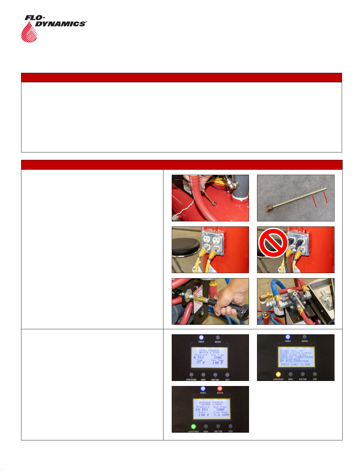
Connect the red service hose to the cooler inlet line and the
blue service hose to the return line of the cooling system.
Once the unit reaches 140 degrees, press the STOP
button.
Press the manual air purge button to clean out the lines.
Remove the top half of the filter housing and place the
screen filter into a waste bucket/container.
Move the Flow Control Valve to position 4.
Use the MODE button to select “START PURGE”. This will
run the initial purge for 7.5 seconds to purge the cooler and
line with clean fluid. Repeat until clean fluid is observed.
Clean the screen filter if needed, and reassemble the filter
housing.
Move the Reverser Valve toward the blue hose coming
from the cooling system’s return line. This will backflush the
cooling system.
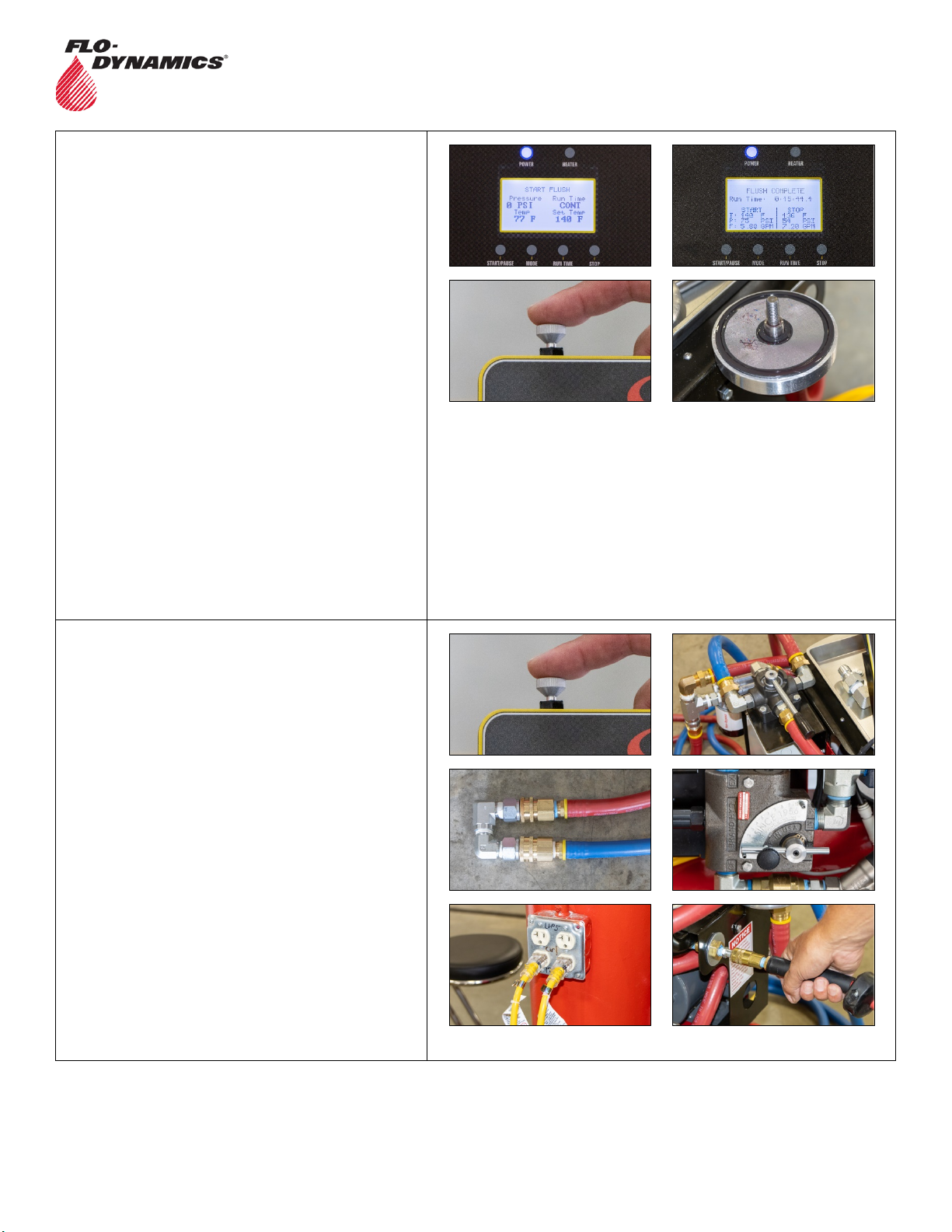
Use the MODE button to select “START FLUSH”. Use the
RUN TIME button to select the flush cycle time. It is
suggested that the initial flush runs for 15 minutes to
capture initial contaminants within the cooler system.
Press START/PAUSE and check the following:
oSecure fill cap
oSecure filter screen
oCheck fluid level
oCheck all connections
oSet flow rate
oSet flow direction
Press the START/PAUSE button to start the flush cycle.
At the end of a flush cycle, the flusher will stop and signal
with an audible sound. The display will show “FLUSH
COMPLETE” with before and after flush cycle results.
Press the manual air purge button to clean out the lines.
Remove the top half of the filter housing, note debris on
filter screen, clean the screen, and reassemble the filter
housing.
Repeat flush cycle selecting a desired time using the RUN
TIME button from 15-120 minutes.
NOTE: With an initial flush completed, you can now run
longer flush cycles along with switching the flow direction
using the reverser valve between flush cycles.
Move the Reverser Valve toward the red service hose.
Use the MODE button to select “START FLUSH”.

TTCF-9A
Variable High Flow Heated
Hydraulic Component Flusher
40201409
QUICK START
INSTRUCTIONS
Flo-Dynamics, Inc. • 3300 Reedy Drive • Elkhart, IN 46514 • 800-303-5874 Page 3of 5
Press START/PAUSE and check the following:
oSecure fill cap
oSecure filter screen
oCheck fluid level
oCheck all connections
oSet flow rate
oSet flow direction
Press the START/PAUSE button to start the flush cycle.
At the end of a flush cycle, the flusher will stop and signal
with an audible sound. The display will show “FLUSH
COMPLETE” with before and after flush cycle results.
Press the manual air purge button to clean out the lines.
Remove the top half of the filter housing, note debris on
filter screen, clean the screen, and reassemble the filter
housing.
Note: Alwaysuse the manual air purge button prior to
removing the top portion of the screen filter housing to
clean out the cooler system and service hoses.
Note: A flush cycle time can be changed anytime by
pressing the RUN TIME button to select a different flush
cycle time.
Repeat until desired system cleanliness is achieved.
Use the manual air purge button to clean out the cooling
system and service lines with the Reverser Valve in either
flow direction, then place in bypass (middle) position.
Remove the service hoses from the system being cleaned,
and use the “U” adapter to connect the hoses together.
Clean the filter screen and reassemble for the next
cleaning.
Move the Flow Control Valve to a minimal flow position.
Unplug the flusher and disconnect shop air.

TTCF-9A
Variable High Flow Heated
Hydraulic Component Flusher
40201409
QUICK START
INSTRUCTIONS
Flo-Dynamics, Inc. • 3300 Reedy Drive • Elkhart, IN 46514 • 800-303-5874 Page 4of 5
ADDITIONAL FUNCTIONS
FILL THE TANK
Remove the fill cap and add enough hydraulic fluid to bring
the level between the marks on the dipstick. When
checking the level, do not thread the dipstick into the tank.
CAUTION: To prevent hydraulic fluid from overflowing
during a flush cycle or when air purging, do not run with
fluid higher than high-level mark on dipstick.
Replace the fill cap when full level is reached.
DRAIN THE TANK USING OVERRIDE LEVEL SENSOR MODE
CAUTION: To prevent burns, only drain tank when fluid is
below 100 degrees.
Connect the drain hose adapter to the red service hose.
Move the Reverser Valve toward the red service hose.
Place the drain hose adapter into a suitable waste
container.
Move the Flow Control Valve to position 3.
CAUTION: Make sure the flow rate is set to a low level to
prevent a high fluid flow intothe waste container.
Use the MODE button to select “START OVERRIDE
LEVEL SENSOR”.
Press the START/PAUSE button.
Check the following:
oSecure fill cap
oSecure filter screen
oCheck fluid level
oCheck all connections
oSet flow rate
oSet flow direction
Press the START/PAUSE button to begin draining. The unit
will run for 10 seconds. Repeat until the unit is drained.
NOTE: There is still approximately one gallon left in the
tank. To completely drain, see “Completely Drain for Fluid
Type Change” procedure below.

TTCF-9A
Variable High Flow Heated
Hydraulic Component Flusher
40201409
QUICK START
INSTRUCTIONS
Flo-Dynamics, Inc. • 3300 Reedy Drive • Elkhart, IN 46514 • 800-303-5874 Page 5of 5
COMPLETELY DRAIN THE TANK FOR FLUID TYPE CHANGE
Perform the “Drain Tank Using Override Level Sensor
Mode” procedure above.
Place a suitable waste container below the inlet “T”.
Remove the pipe plug on the inlet “T” and use the handle to
tilt the unit to drain the remaining fluid in the tank.
Table of contents
Other FLO-DYNAMICS Industrial Equipment manuals