FLO-DYNAMICS CMS-120 Programming manual

CMS-120
Coolant Management System
40201194
QUICK START
INSTRUCTIONS
Flo-Dynamics, Inc. • 3300 Reedy Drive • Elkhart, IN 46514 • 800-303-5874 Page 1of 8
OPERATION
SAFETY RECOMMENDATIONS
Use extreme safety measures when working around a running engine, pressurized storage vessels, and automotive chemicals.
Always block the vehicle’s drive wheels.
Ventilate the vehicle’s exhaust if engine will be started.
Always wear safety glasses.
Protective gloves are recommended.
PREPARATION
Inspect the engine and the visible coolant system
components for any signs of damage or unusual wear.
Note the coolant level before beginning the service. If low,
see “COOLING SYSTEM PRESSURE / LEAK CHECK”
procedure to verify the system’s condition.
Depending on the desired service, make appropriate
connections (lowest and highest point) on the vehicle’s
coolant system.
Plug any open ports venting to the atmosphere (i.e.
overflow hose or a system vent cap).
To prevent running out of coolant and ingesting air, ensure
coolant tank level is showing at least 3 gallons on the sight
tube.
PERFORM COOLANT DRAIN and CLEAN OPERATION
DRAIN COOLANT FROM VEHICLE INTO COOLANT
TANK
Obtain a coolant sample if needed.
Move the Flow Control to “OFF” and connect shop air.
Connect the red service hose to highest point, the black
service hose to the lowest point, and open the ball valves.
Turn all control panel valves to the YELLOW position.
Move the Flow Control to “ON”.
The system will begin to drain.

CMS-120
Coolant Management System
40201194
QUICK START
INSTRUCTIONS
Flo-Dynamics, Inc. • 3300 Reedy Drive • Elkhart, IN 46514 • 800-303-5874 Page 2of 8
When air is seen in the black hose, turn Tank Control and
Assist Control to VENT and Vacuum Control to OFF.
When air pockets/coolant stop moving in the service hoses,
move the Flow Control to “OFF”.
Close the ball valves and remove the service hoses.
PERFORM COOLANT FILL OPERATION
RETURN COOLANT TO VEHICLE AFTER SERVICING
Move the Flow Control to “OFF” and connect shop air.
Connect the red service hose to highest point, the black
service hose to the lowest point, and open the ball valves.
Turn all control panel dials to the GREEN position.
Move the Flow Control to “ON”.
The system will begin to fill.
When the coolant level is at the “cold” level of the
expansion tank or seen in the red hose, the system is full.
Turn Tank Control to VENT and Vacuum Control to OFF.
The coolant level will adjust.

CMS-120
Coolant Management System
40201194
QUICK START
INSTRUCTIONS
Flo-Dynamics, Inc. • 3300 Reedy Drive • Elkhart, IN 46514 • 800-303-5874 Page 3of 8
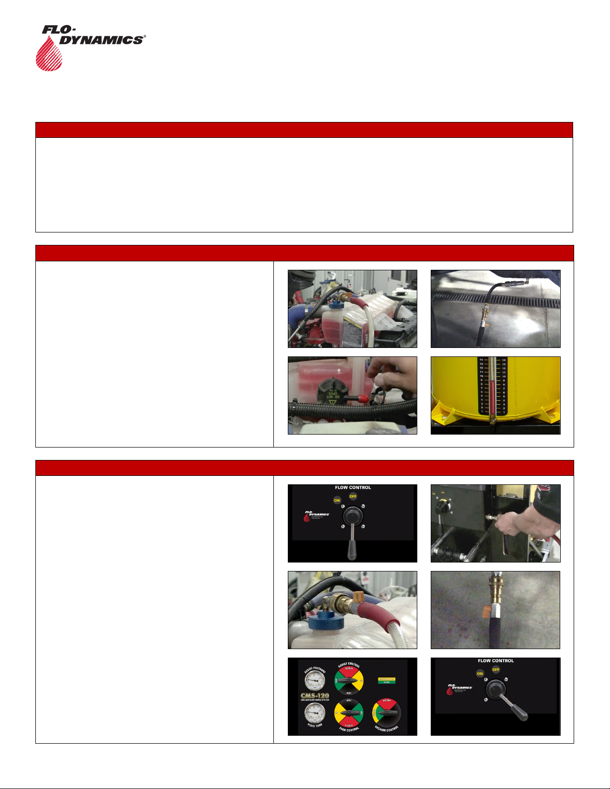
When the coolant returns to the “cold” level on the
expansion tank, turn Assist Control to VENT.
When the cooling system stabilizes and both gauges show
zero, move the Flow Control to “OFF”.
TO ADJUST COOLANT LEVEL IF IT’S TOO HIGH
Turn Tank Control and Vacuum Control to YELLOW and
Assist Control to VENT.
Move the Flow Control to “ON” until the desired coolant
level is reached.
Move the Flow Control to “OFF” and turn Vacuum
Control and Assist Control to VENT.
Close the ball valves and remove the service hoses.
NOTE: If cooling system overfills and coolant is seen in the
top service hose going into the vacuum generator overflow
filter, stop flow immediately by moving Flow Control to
“OFF”. See “VACUUM GENERATOR OVERFLOW FILTER
REPLACEMENT” procedure to empty overflow filter
assembly.
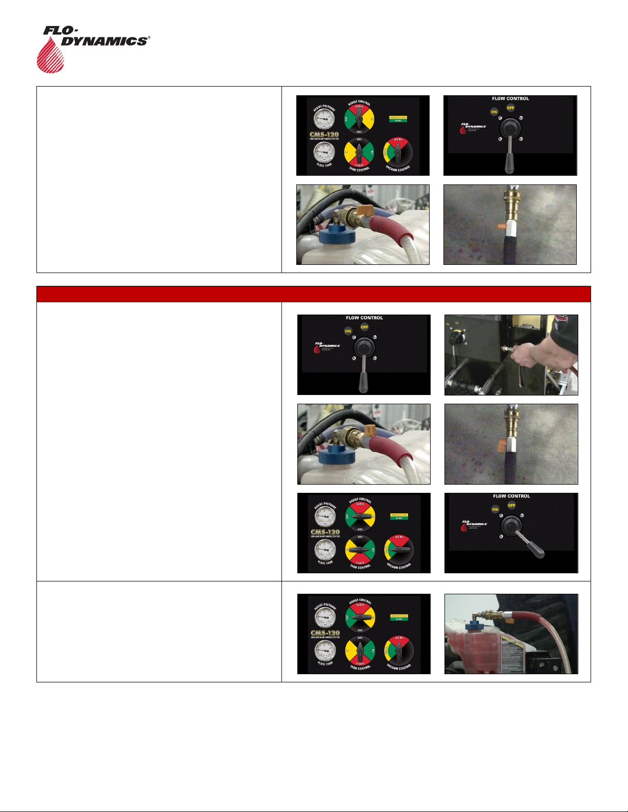
TOP-OFF PROCEDURE / COOLANT LEVEL TOO LOW
NOTE: The following procedure is performed with the red
and black service hoses still connected from filling the
cooling system in the above procedure.
Turn Tank Control to Green, Assist Control to VENT and
Vacuum Control to OFF.
Move the Flow Control to “ON”.
When coolant is at the correct level, move the Flow
Control to “OFF”, Tank Control to VENT.
When the cooling system stabilizes and both gauges show
zero, close the ball valves and remove the service hoses.

CMS-120
Coolant Management System
40201194
QUICK START
INSTRUCTIONS
Flo-Dynamics, Inc. • 3300 Reedy Drive • Elkhart, IN 46514 • 800-303-5874 Page 4of 8
ADDITIONAL FUNCTIONS
COOLING SYSTEM PRESSURE / LEAK CHECK
Move the Flow Control to “OFF” and connect shop air to
the machine.
Close the ball valve on the red service hose. Connect the
red service hose to the top of the radiator using the
appropriate adapter and open the ball valve.
Turn Tank Control and Assist Control to YELLOW
position.
Move the Flow Control to “ON”.
The system will pressurize to 10-15psi.
Turn Tank Control to RED and observe the Fluid Tank
pressure gauge. If there is a loss of pressure, then there is
a leak in the cooling system.
When enough time has elapsed to properly perform a
pressure check, move the Flow Control to “OFF” and Tank
Control and Asist Control to VENT.
Close the ball valve on the red service hose and remove
the red service hose. Remove the adapter from the radiator
and replace the cap.

CMS-120
Coolant Management System
40201194
QUICK START
INSTRUCTIONS
Flo-Dynamics, Inc. • 3300 Reedy Drive • Elkhart, IN 46514 • 800-303-5874 Page 5of 8
FILL TANK – METHOD 1 POUR IN
Ensure there is no pressure or vacuum in the new coolant
tank by pulling up on the relief valve ring on top of the tank.
Remove the fill cap. Add the required amount of new
coolant and replace the fill cap.
FILL TANK - METHOD 2 VACUUM MODE
If the Fluid Tank gauge indicates pressure or a vacuum,
turn Tank Control to VENT to equalize tank to zero.
Close the ball valve on the BLACK service hose and
connect the open-end adapter.
Turn Tank Control and Vacuum Control to Yellow.
Move the Flow Control to “ON”.
Place the open-end adapter into a new coolant container
and open the ball valve on BLACK hose.
When the coolant level in coolant tank reaches the desired
level, move the Flow Control to “OFF” and close the ball
valve on the BLACK service hose.
Move Vacuum Control to OFF and move Tank Control to
VENT.

CMS-120
Coolant Management System
40201194
QUICK START
INSTRUCTIONS
Flo-Dynamics, Inc. • 3300 Reedy Drive • Elkhart, IN 46514 • 800-303-5874 Page 6of 8
DRAINING THE TANK
Close the ball valve on the black service hose and connect
the open-end adapter.
Turn Tank Control and Assist Control to GREEN.
Move the Flow Control to “ON”
Place the open-end adapter into an approved coolant waste
container and open the ball valve. Drain until the tank is
empty.
Move the Flow Control to “OFF” and Tank Control and
Assist Control to VENT to release pressure in the tank.
Dispose of used coolant in accordance with local and state
requirements.
EMPTY OVERFLOW BOTTLE
Release the Velcro strap and remove the overflow bottle.
Empty contents into an approved coolant waste container.
Rinse out and replace using Velcro strap.
VACUUM GENERATOR OVERFLOW FILTER REPLACEMENT
The vacuum generator overflow filter should be emptied
when it is more than 1/3 full.
Remove the reservoir by turning it counterclockwise. Empty
the reservoir contents into an approved coolant waste
container, rinse out the reservoir, and replace the filter if
necessary.
After ensuring the rubber O-ring is in place, reinstall the
reservoir by turning clockwise until seated.

CMS-120
Coolant Management System
40201194
QUICK START
INSTRUCTIONS
Flo-Dynamics, Inc. • 3300 Reedy Drive • Elkhart, IN 46514 • 800-303-5874 Page 7of 8
COOLANT FILTER REPLACEMENT
If pressure or a vacuum is shown on either tank gauge,
depressurize the tanks by turning Tank Control and Assist
Control to VENT.
Close the ball valve on the black service hose and connect
the open-end adapter.
Turn Tank Control and Vacuum Control to GREEN and
move the Flow Control to “ON”.
Place the open-end adapter into an approved coolant waste
container and open the ball valve.
NOTE: The reservoir will not completely empty and will only
empty past the threads, so the reservoir may be removed
without spillage.
Once at this level, move the Flow Control to “OFF”, turn
Tank Control to VENT, and Vacuum Control to OFF.
Remove the reservoir by turning it counterclockwise. Empty
the reservoir contents into an approved coolant waste
container, rinse out the reservoir, and replace the filter if
necessary.
After ensuring the rubber O-ring is in place, reinstall the
reservoir by turning clockwise until seated.

CMS-120
Coolant Management System
40201194
QUICK START
INSTRUCTIONS
Flo-Dynamics, Inc. • 3300 Reedy Drive • Elkhart, IN 46514 • 800-303-5874 Page 8of 8
REMOVE COOLANT FROM A VEHICLE’S EXPANSION / DE-GAS BOTTLE
Move the Flow Control to “OFF” and connect shop air to
the machine.
Close the ball valve on the black service hose and connect
the open-end adapter.
Turn Tank Control and Vacuum Control to YELLOW and
Assist Control to VENT.
Move the Flow Control to “ON” until the desired coolant
level is reached.
Move the Flow Control to “OFF” and turn Tank Control
and Vacuum Control to VENT.
Close the ball valves and remove the service hoses.
Table of contents
Other FLO-DYNAMICS Industrial Equipment manuals