Floataway TRANQUILITY User manual

1
Floataway Installation Manual 230v 50Hz Tranquility 2017 - v3
Installation Manual
Tranquility 2017 [v3]
230v 50Hz
Revised March 2015
PLEASE READ THIS MANUAL TO THE END BEFORE STARTING
[ Updated : MAY 2017 ]
Floataway is a registered trademark of Cosine Limited.
8 Ironside Way, Hingham Business Park, Hingham, Norfolk, NR9 4LF, UK
Ofce +44 1953 851 515 Factory +44 1953 851 861
Info@oataway.com www.oataway.com

2
Floataway Installation Manual 230v 50Hz Tranquility 2017 - v3
Please read through all the instructions before beginning the installation. This rst section
repeats the information which was supplied in our technical information for preparing the
oat room for a Floataway Float Pool.
Before You Get Started
Page.
• First check the room 3
• Inspect the proposed reception area. 3
• Plan where to put the salt and parts during the installation. 3
• Check the Cables / Electrical Supplies 4
The Installation : Sequence of Parts Required
Page
• The high temperature insulation panel 5
• The silicone heater membrane sheets 5
• The heater panels 5
• The tub 5
• The ground noise isolation system 6
• The skimmer and pre-lter 7
• The dome 7
• The door 7
• The hinges (tted to the door) 8
• The suction assembly and pump connections 9
• The lter connections and the back panel 9
• Water Isolation check 10
• The jacks / door motors 10
• The auto doser - liquid disinfectant 11
• The control box and its connections 14
• The control box diagrams 15
• The electrical supply cables 16
• The water level sensor 17
• The temperature probe 17
• The back-up battery 17
• XLR connectors 18
• Room light control 18
• Under water lights 19
• The air hose connections 20
• Music speaker 20
• Intercom system 21
• Music system 22
• Fitting the side panels 22
• Identifying parts of the LAN cable 23
• The remote control 24
• Recommended values 29
• The water and salt 30
• Troubleshooting common problems 31
• Remote Quick Guide 33
3
Floataway Installation Manual 230v 50Hz Tranquility 2017 - v3
First check the room
The Float room needs to:
• Be big enough, min. 3.5m by 3m wide (11’6” by 9’10”).
• Have a oor loading capacity of at least 5kN per square meter.
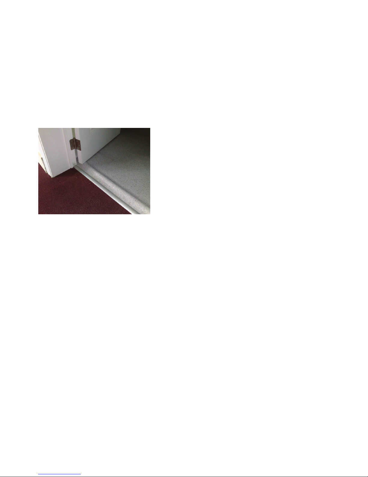
• Have a waterproof, bunded*, non slip oor (e.g. Altro Marine 20)
• Have a 230v 50Hz electricity supply as needed
• Have ventilation (fan if no window)
*Bunded means with raised edges so
that any leak is retained within the oor
area. Typical details are shown in the
photo below. Floataway will not be held
responsible for damage to adjacent room
oors or to ceilings below the oat room
if our advice has not been followed.
For commercial use, the room must:
• Have an emergency light
• Have appropriate re warning and escape
• Have appropriate disabled use equipment and signs, if applicable.
Check the access route through which the parts must be carried.
Inspect the proposed reception / centre
There must be a position for the CD player or sound source(e.g. iPad/iPod), and a place for the
remote control unit in the reception area. Check that the LAN cable has been installed for the
remote box. The remote control should not be easily accessible to the visiting public.
Check how much hot water will be available and if a hose will be needed to ll the product.
Plan where to put the salt and parts during the installation.
4
Floataway Installation Manual 230v 50Hz Tranquility 2017 - v3
The Cables / Electrical Supply
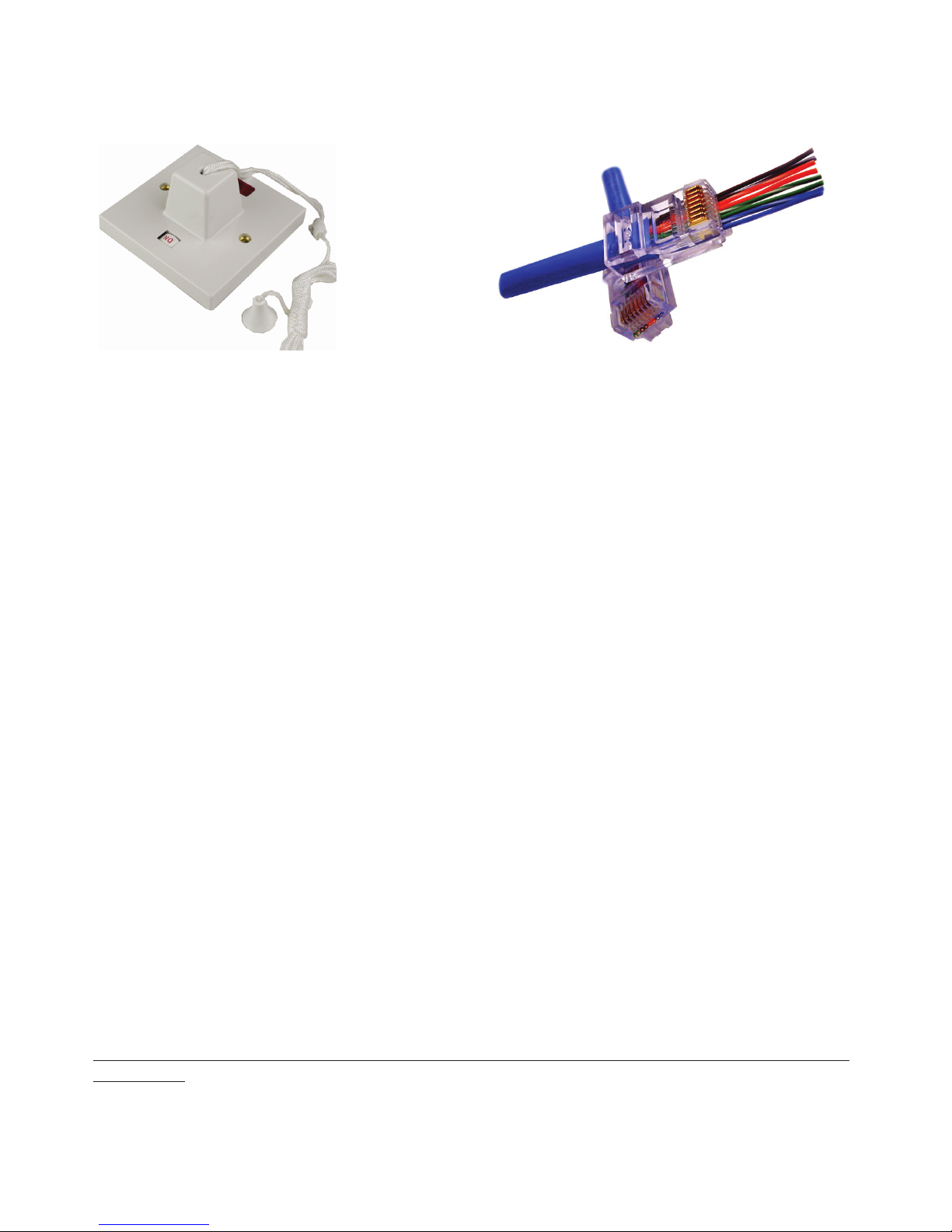
The Data Cables:
The control system uses standard Industrial CAT5/6 LAN cable and RJ45 sockets. It must not be
part of a network but have it’s own dedicated cable. The cable should be installed with the control
box and remote. A second LAN cable is required for an intercom option. We recommend installing
a spare LAN cable at this time in case of damage to the cable.
2x Cat 5 or 6 LAN cables direct (no breaks/routers) from the back of the tank to the location of
the remote. The second is spare, but highly recommended. You need a 3rd if you have intercom or
think you may add it in the future.
Electricity Supply:
There should be a waterproof connection outlets for the single phase 230v 50 Hz. Supply. The
mains supply should be in a waterproof terminal point (or socket in some countries) near to the
location of the technical pack.
1x 230v 50Hz supply - 20A
Check that the voltage of the pool is suitable for the supply installed.
Connecting a 110 V pool to a 230 V supply or a 230 V pool to a 110 V supply will cause damage to
the pool components and may be dangerous. The supply should have a two-pole interrupter such
as a ceiling pull switch in the room. This interrupter must have a suitable current rating for the fuse
or breaker on each supply. The interrupter switch must be 2m (6’) from the water line of the pool.
Fusing and RCD (Residual Current Device) or GFCI :
• The pool should be supplied through it’s own RCD or GFCI (differential) with a trip current
of 30 mA / Class A and through an isolating switch.
• There must also be a fuse or circuit breaker in the line.
• For 230v installations the fuse should be 20 Amp with suitable cables.
We recommend that the electrical installation of the supply be done by a suitably qualied
electrician.
5
Floataway Installation Manual 230v 50Hz Tranquility 2017 - v3
Please read through this Manual before beginning the installation. If you are not condent
of success, please hire an electrician to do the installation for you. Floataway will not be
responsible for installation errors caused by not using these instructions.
The Heater Insulation Panel
The heater insulation is a thick high temperature rigid aluminium
coated mat. The tub sits on top of this piece and is positioned
approximately 8 inches from the back wall in the oat room.
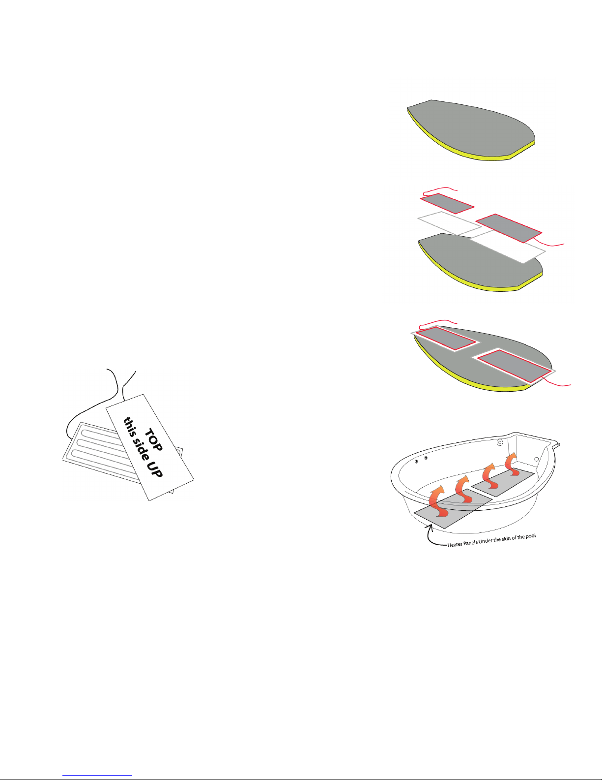
The Silicone Heater membrane sheets
The heaters must sit on top of the silicone sheet membrane, it is
a white soft foamed rubber sheet 2mm thick. The silicone sheet
is WHITE and comes rolled up. Lay the silicone sheets down on
the insulation panel ready for the heaters.
The Heater Panels
The heater panels, smooth metal side facing upwards, are posi-
tioned over the high temperature insulation. The drawing below
shows both sides of the heater panel. Be sure that the coil sides
are facing the insulation so that you see the smooth side facing
you as shown below right.
The drawing shows the correct
position of the heater panels
The heater with a longer wire
goes at the front of the product.
The cables run back to the con-
trol box on the tank and should
not be trapped under the tub.
Check that there are no foreign bodies on the top surface of
the heater, or on the bottom of the tub, before the tub is added.
Small hard objects may break the bottom of the tub when water
is added, or cause local hot spots or noises.
The heaters are not supplied connected to the control box and must be fed through cable ties
along the tank and then the glands and connected to ground (5), neutral (2), series connection(8)
and switched live (Heater MCB 1) connections in the control box. (See connection information
under “control box” section.) A small portion of the heaters should stick out from under the tub (ap-
proximately an inch) to enable earth bond testing.
The Tub
Place the tub gently onto the insulation and heater panels. The heater panels and insulation may
be walked on during this manoeuvre. Remove any packaging from the tub and clean it thoroughly,
rst using soapy water, then if necessary lighter fuel (not acetone) for stubborn marks. Position
the tub so that its base sit exactly on top of the insulation.
6
Floataway Installation Manual 230v 50Hz Tranquility 2017 - v3
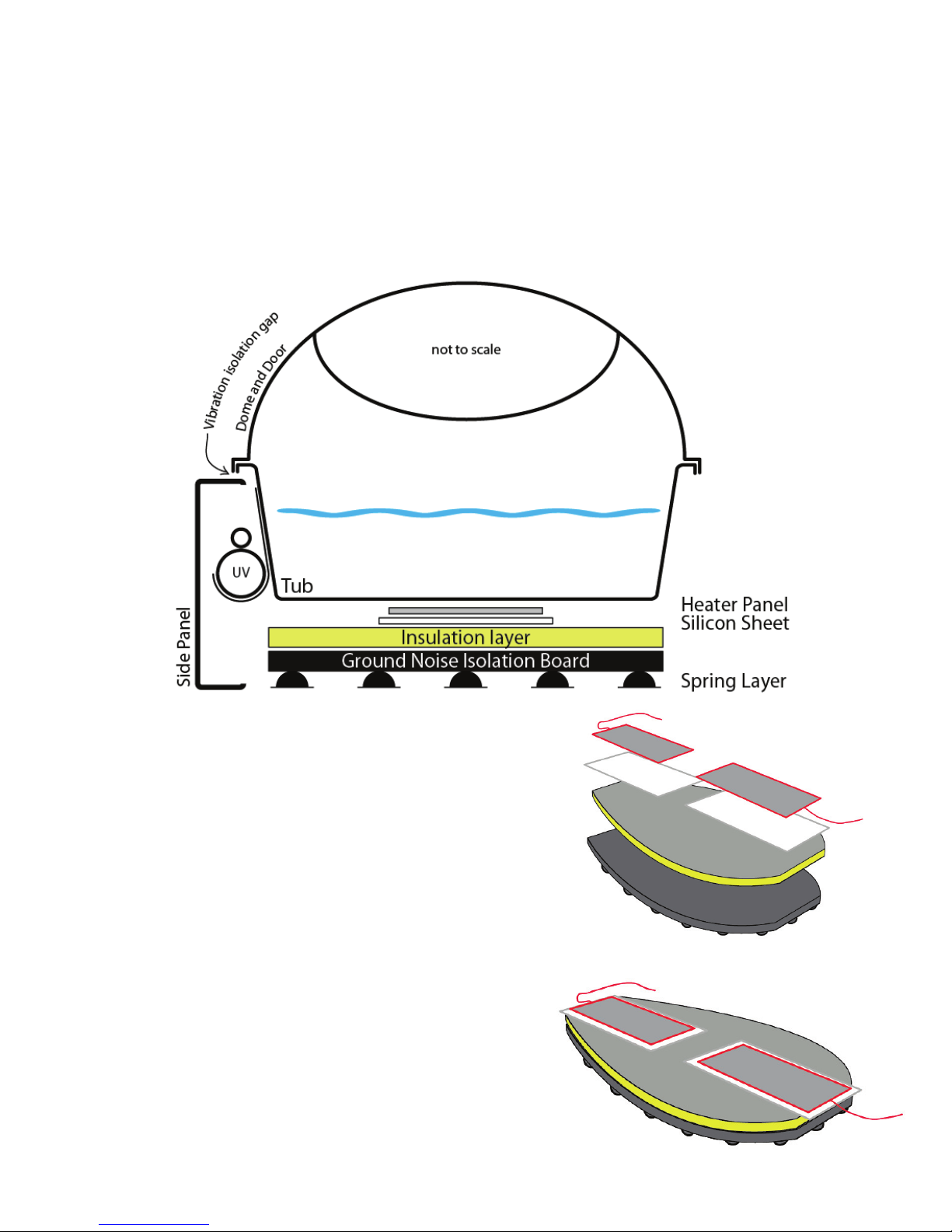
Ground Noise Isolation System
The optional ground noise isolation system (GNIS) is designed to reduce the frequencies trans-
ferred through the ground into the water. The rubber springs will only work once the tank is lled
and salt is added as the system is designed for the working load of the product so will not work
correctly with the tranquillity empty.
Typical noises that can be heard through the water include road noise, toilets ushing, foot steps,
doors closing, these type of sounds can be transmitted through the oor due, the GNIS will reduce
these to give a superior oat experience.
When installing, the heavy GNIS board is placed down
where the standard insulation would be tted, the insu-
lation panel is thinner to account for the height differ-
ence.
The GNIS system will only work on the parts that
are then resting on top of the board. The side panels
around the Tranquillity do not sit on the board. It is very
important that the side panels do not touch the tub any-
where. The pump and sits on the oor and is connected
to the tub through a rubber hose, as is the lter housing
return pipe - these are the only parts that connect the
isolated tub to the ground.
The GNIS board can be seen here with the insulation,
silicone heater mats and heaters ready for the tub to
be placed down.
7
Floataway Installation Manual 230v 50Hz Tranquility 2017 - v3
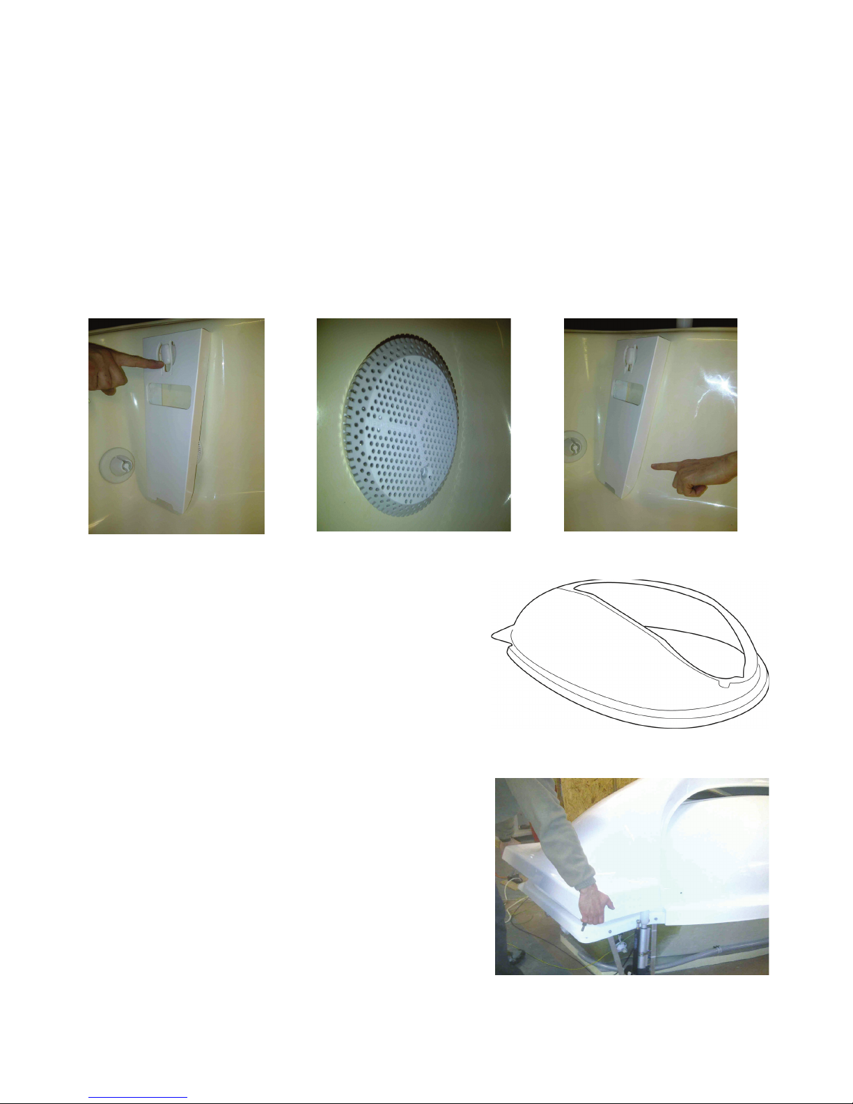
The Skimmer and Pre-Filter
The skimmer is located at the back of the tub and is made of white plastic with a slot indicating the
correct water level (½” above the bottom of the slot) but is not shipped attached to the tub.
Remove it from the accessories box and put it in place as seen on the right hand photo below.
You will rst need to attach the skimmer to its clip (photo below left) at the top and then push the
bottom section over the prelter which comes attached to the tub (shown below in the middle), us-
ing some force. The prelter prevents debris such as earplugs entering the pump.
The skimmer’s correct position is ush against the tub (as shown below right). Do not be afraid to
give it a good strong “hit” to get it into its correct place. The skimmer and prelter must be re-
moved once per week for cleaning in soapy water.
The Dome
When the tub has been cleaned, carry the dome in and
place it carefully onto the tub. Note that the dome can be
removed for cleaning by lifting, even after the door is
tted.
Note : when in operation, Do not leave the dome off for
a prolonged period, when not in a oat session, the door
automatically closes if left open too long.
The Door
Bring in the door carefully and place it onto the dome. The
hinges are tted to the door and will need to be guided
into the mounting holes at the back of the tub.
8
Floataway Installation Manual 230v 50Hz Tranquility 2017 - v3
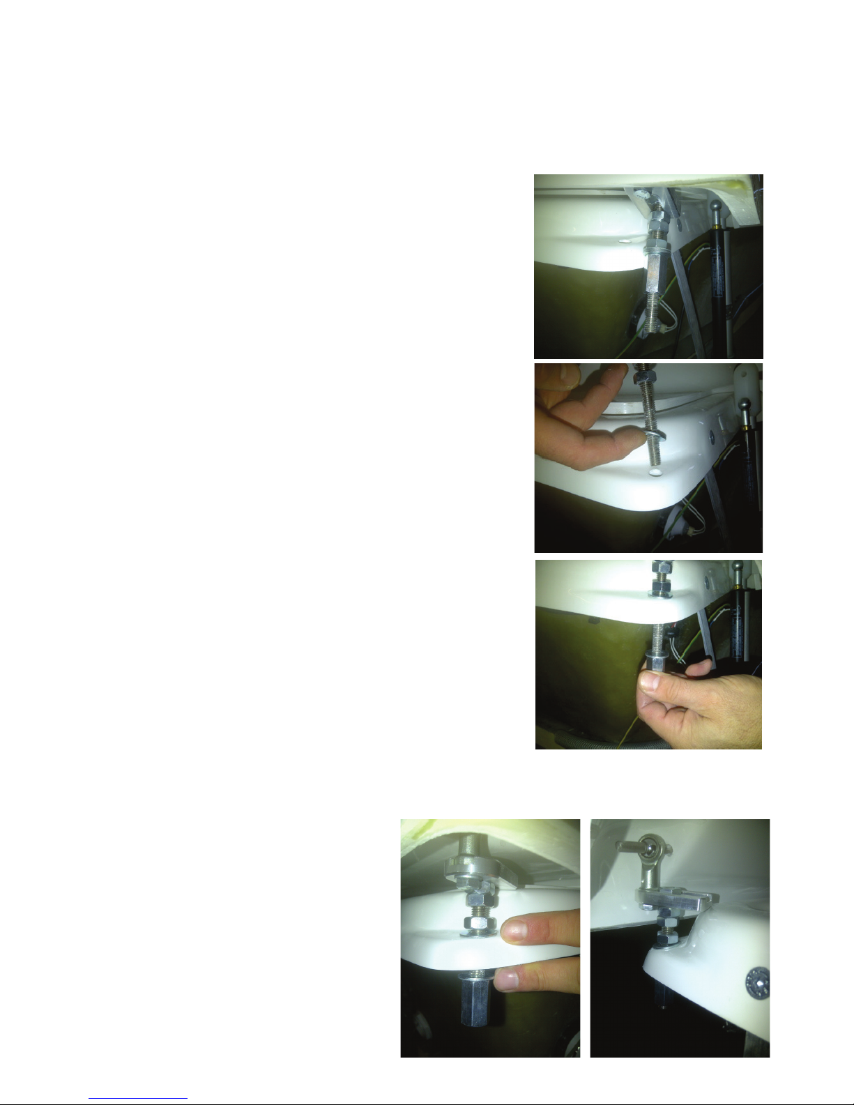
The Hinges
The door is held by two hinges which come tted to the door. They must be inserted into the pre-
drilled holes in the corners of the tub. This photo shows the hinge as it comes attached to the
door.
To t the hinges, on each side :
1. Remove the lower long M10 nut from the retaining bolt and
the bottom washer.
2. Lift one end of the door a little, so that the bolt can enter the
hole in the tub leaving the top washer to sit on top of the back
corner of the tub.
3. Add the washer underneath and the long nut and tighten by
hand.
4. Repeat on the other hinge.
5. Check the door opening manually.
6. Place a towel over the back of the dome to act as a spacer
and close the door.
7. The hinges can be fully adjusted. The nuts securing the
hinges to the tub are also used to adjust the height of the door.
The two adjacent nuts towards the top of the hinge are used to
adjust the door backwards and forwards.
8. After testing whether the door opens and closed correctly,
adjust if necessary, and fully tighten all the bolts using the two
17mm spanners provided in the accessories box. Check once
the control box is connected before you t the side panels.
9. Check that the hinges are well located on the 8mm pins of
the door and retained by spring “push on” retainers as shown
on the photo below right. These have been factory installed.
10. Recheck the door opening and remove the towel.
The photo on the right shows the installed
hinge in its correct position.

9
Floataway Installation Manual 230v 50Hz Tranquility 2017 - v3
The Suction Assembly and Pump Connections
Carry in the pump and the suction hose and place it behind
the tub, leaving at least 10” behind the tub to the back wall.
The 1 1/2” black rubber hose forms the suction assembly
which connects the tank outlet to the pump. The tub tting
includes a plastic tube outlet and elbows
The photos show a 220v TE6 pump, depending on your
specication your pump may be different.
Fit the 1 1/2” rubber hose to the plastic tube and position
two hose clips as shown in the photo above right, pushing
the hose fully onto the pipe. Tighten the clips around the
hose using the hose clip driver (7mm) provided.
Check before connecting, that all the hose clips are aligned
so that they can be tightened easily and that they can be
easily reached in the future. When the water has heated
up, it is necessary to re-test the tension on these ttings
The Filter Connections and Back Panel
Bring in the back panel with its lter housing and auto-
dosing unit already tted. Position it behind the tub.
You should leave at least 10” to the back wall for future
maintenance work.
Note: the lter inlet is at the top. The exit tube is at the
bottom of the lter housing. Connect the pump outlet to the
top of the lter, as shown in the photo on the right.
Then connect the hose from the UV lter (optional) to the
bottom of the lter housing as shown on the photo here :
Each tube connection has two clips for reliability.
Make sure all the pipe clips are tight.
Top
10
Floataway Installation Manual 230v 50Hz Tranquility 2017 - v3
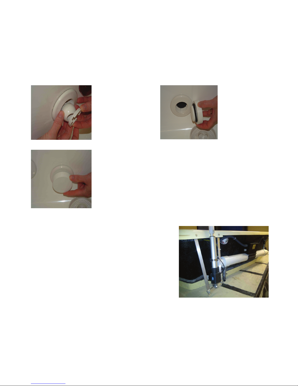
Water Isolation Check
If servicing is required after installation (for example to change a pump), two threaded plugs are
tted to the back panel which can be screwed into the suction and water delivery ttings inside
the tank to shut off the water ow to the pipes and pump. The photos below show the pre-lter
removed behind the skimmer and the plug screwed into the pre-lter’s place.
The jet also unscrews, as shown in the photo, to allow one of the two plugs provided to be put in
its place to shut off the water supply when changing or servicing a pump.
Remove the ball of the
water jet by rotating the
retaining ring
Remove the
skimmer and
the pre lter
Once the jet tting and the pre lter are removed it is possible to
use the isolation bungs supplied, they simply screw into the tting
and hold the water in the tank; they do not need to be very tight.
This is useful if you need to work on the technical parts with water
in the pool.
The Jacks
The jacks (lift motors) open the door and are supplied
tted to the tub and to their brackets at the back of the
tank.
If you must remove the jacks, please note :
One has a longer cable to reach to the far side from the
control box, which is on the suction side of the tub.
Make sure the jack brackets are tight.

11
Floataway Installation Manual 230v 50Hz Tranquility 2017 - v3
POOL
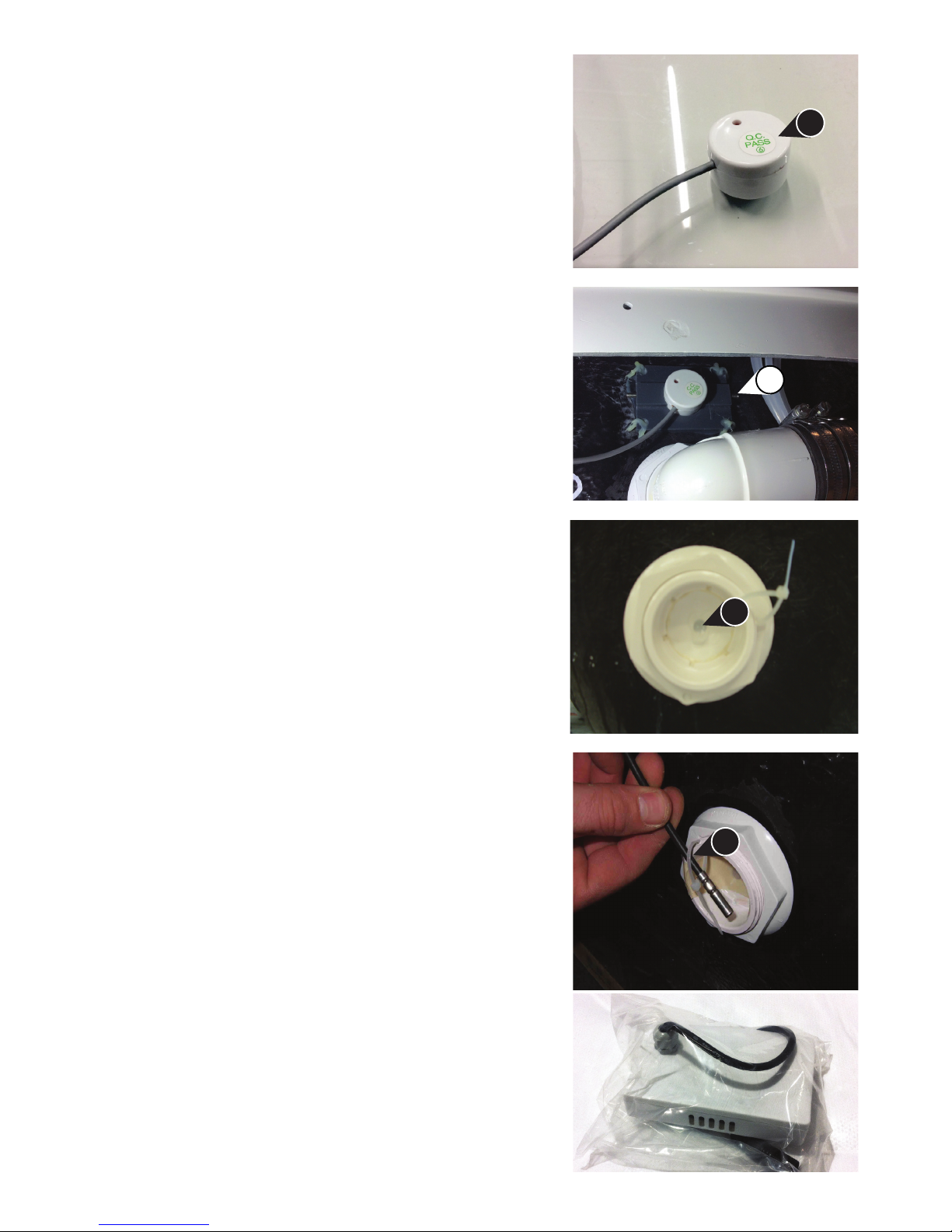
The Auto Doser - Liquid Disinfectant Upgrade Option.
The auto doser is a 12v system, the pump runs when the main water pump runs. The time is
controlled by the program and is adjustable. The liquid disinfectant is stored in the reservoir bottle
and pumped into the tank through the jet behind the weir.
Check the pipe has no bends or kinks. Use the soft rubber connection tubes to t the hose to the
jet hose - secure it with two zip ties. Fit the level sensor to the reservoir bottle in the same way as
the water level sensor.
The bottle and pump are tted at the back of the tank.
The reservoir bottle holds 1Lt. test the system for leaks
with 300ml of fresh water before adding chemicals.
Use gloves and eye protection when lling with disinfectant
The Jet into the tub is tted behind the weir, you can adjust
the length of the jet, it can be replaced also. Make sure the
liquid drips into the water and does not run down the side
of the berglass.
The hose should not dip into the water
The back of the jet is tted with an M14 nut, nger tight
only, do not use tools, if overtightened it can sheer off the
shaft of the jet.
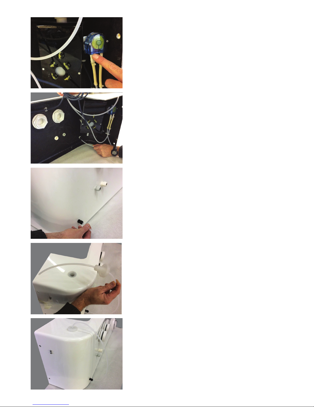
12
Floataway Installation Manual 230v 50Hz Tranquility 2017 - v3
The Pump sucks the liquid from the reservoir and pushes
it into the tank, make sure the direction arrows are correct
when tting the hoses.
Thread the suction hose through the gland seen here.
Pull the hose out making sure not to kink during the
operation.
When the hose is threaded through the lid, it will look
like this. Make sure the hose reaches the bottom of the
reservoir.
The lling cap is removed and then use the funnel to
carefully ll the reservoir - do not overll. ll when empty by
adding 1Lt, do not ll to the brim.
It will look like this when nished.
13
Floataway Installation Manual 230v 50Hz Tranquility 2017 - v3
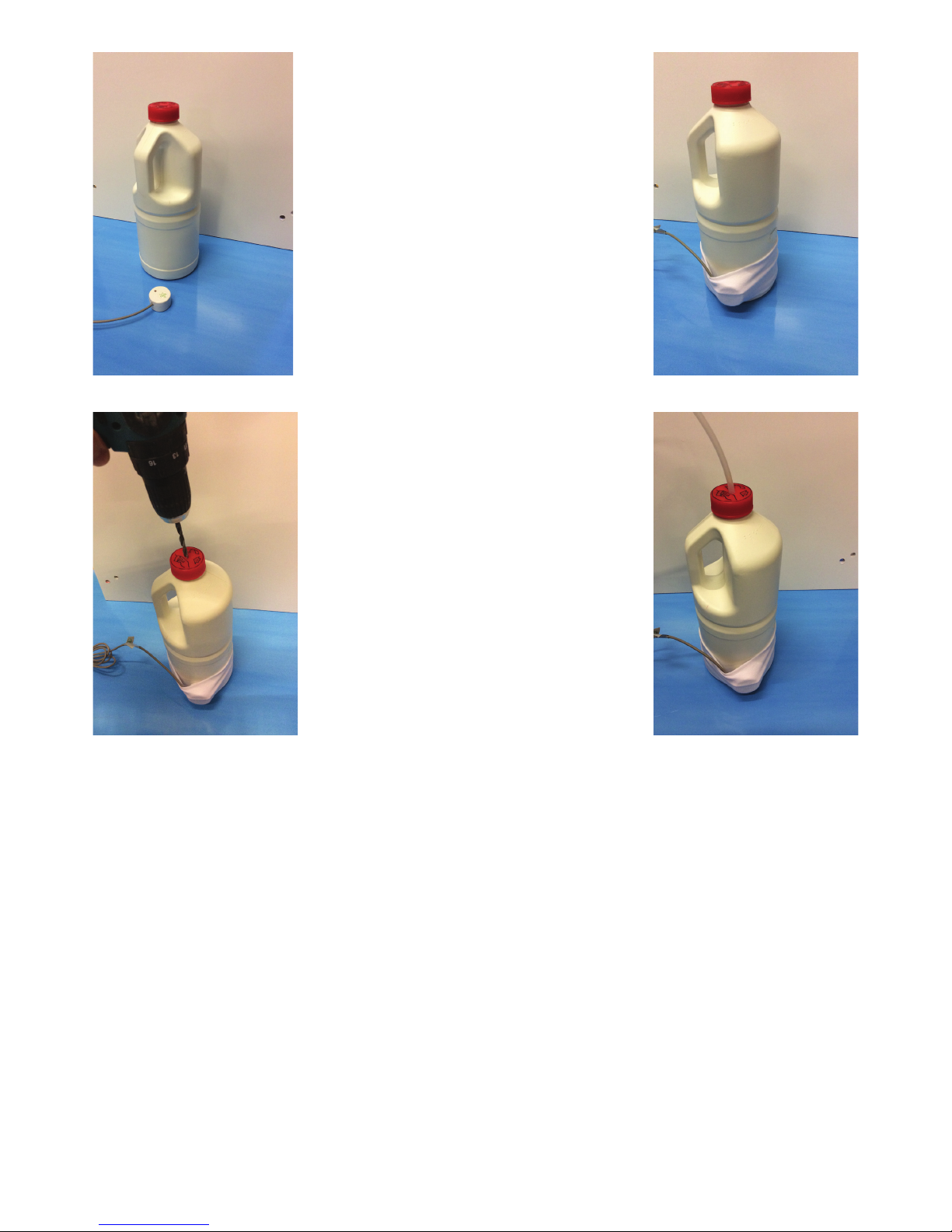
The Auto Doser -
Liquid Disinfectant:
Using a different
disinfectant bottle
- optional
There is a reservoir tted to the techni-
cal pack, but if you choose to use the
bottles your disinfectant is supplied in,
the level sensor can be strapped to the
bottle with the elastic strap.
If the bottle does not have a hole in the
lid, simply drill one to have access for
the pipe.
14
Floataway Installation Manual 230v 50Hz Tranquility 2017 - v3
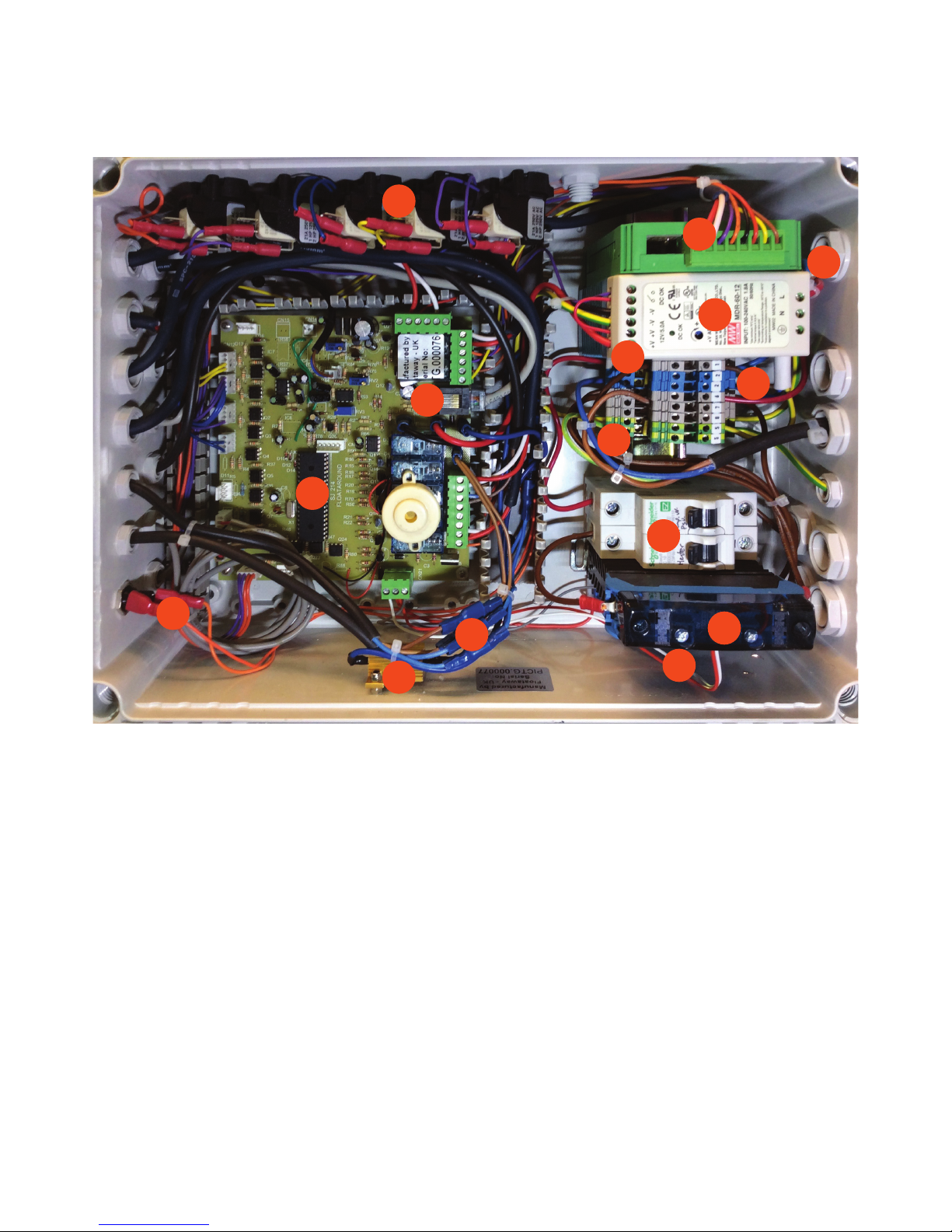
The Control Box and Connections
The Control Box
Description of the control box - Standard setup :
1. The mains or supply cable is at the top right on the photo above.
2. Solid State Relay (SSR) for the heaters.
3. Pump relay (obscured by SSR in this photo)
4. MCBs mains circuits
5. Earth / ground connectors
6. Supply N - 230v 50Hz 20A : N : Terminal 2
7. Supply L - 230v 50Hz 20A : L : Terminal 1
8. Control Power Supply 12v dc (adjusted to 13.5v with no load). (PSU)
9. Floataway fader Audio amplier.
10.Jack (motor door) load resistor
11. Jack (door motor) connectors - 12v
12.LAN type communication socket with a RJ45 plug
13.Air switches for air buttons on tank
14.Main control board
15.Under water Light fuse - 2A
2
3
4
6
7
5
8
9
10
1
11
12
13
14
15

15
Floataway Installation Manual 230v 50Hz Tranquility 2017 - v3
The Control Box Diagrams
PSU UV
230v Supply N
230v Supply L
Heater Pair
Water
Heater SSR
SSR
Earth Supply
Pump
Water Heaters
MCB 2: 10A
Pump,PSU,UV
1
555
6
5
Relay 1
PUMP
11 14
7
2 2 2
8
MCB 1: 10A
Heater 1&2
Heater 2
Pump
SSR Heater SSR Relay
Pump : Relay 1
230V
50Hz
12v Power Supply
Audio Amp
MCB 1: 10A Heater 1&2
MCB 2: 10A Pump,PSU,UV
Supply
230v AC 20A
Live
Neutral
Earth
(hot)
Heater 1
UV
6
5
5
7
2
2
1
8
Ground
PUMP
11
14
Supply
230v 50Hz 20A

16
Floataway Installation Manual 230v 50Hz Tranquility 2017 - v3
The Electricity Cables
The pump and heaters must be connected to the control box.
Do not turn the tank on yet.
The Pump Cable
The pump cable must be fed through one of the cable glands and connected to:
Ground/Earth Terminal 5
Neutral Terminal 2
Switched live for the pump Terminal 7
The UV option (factory tted)
The UV ltration system turns on/off with the pump.
Ground/Earth Terminal 5
Neutral Terminal 2
Switched live for the Pump & UV Terminal 7
The Heater Cables
The heaters are 110V type wired in series pair (see diagram). Feed the 2 heater cables through
the zip ties along the tank towards the control box, and then into two glands and connect to:
Ground/Earth Terminal 5
Neutral Terminal 2
Switched live for the Heaters Heater MCB 1
Heater bridge connection Terminal 8*
*The two heaters are connected together in series - this is VERY important.
Visually check the connections, use a ohm meter to check that there is no short to earth. The
resistance from live to earth measured at the free end of the supply cord should be more than
1M ohm. Finally connect the main supply (which must be, as previously stated, via a GFCI and
isolating switch).
Do not switch the tank on until there is water in the tub and do not switch on if the bottom of the
tank (and therefore the heaters) is covered with Epsom salt which has not been fully dissolved.
Qty V. Hz. item total A. MCB MCB MCB Load Load use
W. W. A Type sub Total of circuit
Heater set 2 230 50 350 700 3 10 C - 3 30%
Pump 1 230 50 370 370 2.5 - -- 2.5 - 25%
PSU 1 230 50 198 198 1.8 - - 1.8 - 18%
UV 1 230 50 50 50 0.2 - - 0.2 - 2%
- - - - - - 10 C 4.5 45%
Supply 20A 1 230 50 - 1318 7.5 - - - - 38%
17
Floataway Installation Manual 230v 50Hz Tranquility 2017 - v3
Connecting the wires
The water level sensor
The white water level sensor (WS) works by capacitance
and is tted on the outside of the panel behind the weir.
It is wired to the control box and must be put into position
and fastened with the tted grub screws (GS), it must be
tted with the red LED facing out. Do not overtighten the
retaining grub screws.
The water level sensor is positioned above the suction
outlet where it detects air when the water level is too low
for proper ow. Make sure the sensor touches the skin of
the tub. A small red sensor is lit when it detects water, it
should be illuminated all the time in normal operation.
The Temperature probe
This is a cable-mounted solid cylinder about 1/4” in
diameter. The temperature housing is pre-lled with
silicone grease. Pass the probe through the cable tie
(CT) and insert the metal tip all the way in to the hole
(TS). Tighten the cable tie around the wire (CT) to secure
it in its place.
The Back-up Battery
The back-up battery has a RED XLR lead. The battery
will maintain the lights and control functions during a
power cut. During the oat session, it will nish the
session as normal, when nished session, it wait roughly
20 min and will shut down completely, in standby it waits
20 min, then shuts down.
The battery is a 12v lead acid type, charged at 13.4v by
the power supply with a 10A fuse. Take care not to plug
the battery into any other connector!
End of Session Chime
The Interface panel has an end of session chime that
sounds when the oat session has come to the end.
WS
GS
TS
CT

18
Floataway Installation Manual 230v 50Hz Tranquility 2017 - v3
The under water lights
The under water light/s are a combination RGB, warm
white and cool white LED unit. The lamp has a 12v supply
and a remote control. The remote can adjust the colour and
brightness of each lamp individually or all at the same time.
Once the lamp colour and brightness has been adjusted to
your room. the lamp will keep those settings, turning on/off
with the oat session control, remembering the settings you
programmed.
The lamps are coded in the factory to your remote, each
lamp uses a different “zone” number. you can reprogram
these numbers if you choose.
To t, unscrew the two clamp bolts by hand.
Remove all packaging and carefully position the lamp into
the lamp housing. You are now ready to re-t the lamp
Carefully slide the lamp into the holder and re-tighten the
two bolts by hand to secure the lamp.
The remote for the lamps uses 2.4G Wi-Fi, it needs to be in
range to control the lamps, the lamps can only be adjusted
when they are ON.
To adjust ALL the lamps at once, use the O/I buttons above
the colour wheel to turn the lamps off/on then adjust the
colour/brightness of the lamps together.
To adjust individual lamps, press one of the “1-4 zone” O/I
button at the bottom of the remote, then adjust the colour/
brightness of that lamp.
To adjust the the colour/white balance use the RGB slider
To adjust the the brightness use the brightness slider
To adjust the the warm/cool white balance use the blue/
yellow slider
To select the Mode to have multi colour fade sequence
etc, use the M button, and then adjust the speed with +/-
buttons.
To LINK a lamp to a zone : turn lamp OFF, and then ON,
press chosen Zone button 3 times within 10 sec.
To UN-LINK a lamp to a zone : turn lamp OFF, and then
ON, press corresponding Zone button 5 times within 10
sec.

19
Floataway Installation Manual 230v 50Hz Tranquility 2017 - v3
The XLR connectors
This photo shows an XLR connector. Depending on which optional
extras you have ordered, there are a number of these coming out
of the control box. Each is colour coded and must be connected to
it’s other half. The male XLR is connected to the tub and the female
XLR is attached to the control box. They simply clip into each other
as shown in the photo on the left.
The XLR connectors
Item Power Colour Code
Lights 12v pulsed 1A max White
Bing-bong sounder 12v pulsed Blue/White
Loudspeaker Audio speakers Green
Back-up battery 12v constant Red
Auto-Doser 12v pulsed Green/Yellow
Filter Sensor 12v switch Yellow
Colour Therapy 12v constant Red/White
Intercom 12v constant Red/White
The Room Light Control
Optional room light control is tted
in a separate box next to the main
control box. This is to keep separate
mains power circuits isolated for safety.
Remember this box may still be live even
when the main power to the oat pool
has been switched off as the supply may
be from a separate lighting circuit.
Use a qualied electrician to connect
up the room light control. It can be used
as part of a standard two-way switching
circuit as seen above.

20
Floataway Installation Manual 230v 50Hz Tranquility 2017 - v3
The Air hoses
The switches in the pool area are
connected by 4mm air hoses, these need
to be connected to the air switches on
the side of the control box.
You simply need to push the black tip
over the small nipple as shown.
Enough tubing has been provided, you
should not need to cut it.
Application Air Button Colour Air Line Colour
Light Button White Yellow
Call Attendant Button Red Red
Music Mute Black Clear/White
Inner Door Black Blue
Outer Door Black Green
The Music/Speaker
The sound is transmitted into the water with a sound transducer that excites the surface of the
technical pack. The wire has been provided to connect to this, it uses an XLR connector with a
GREEN colour code. It is a mono system (one sound source) as stereo does not work underwater
due to the speed of sound in water is different to air. The control box has an amplier built into it,
the sound source is at the remote through a 3.5mm standard headphone socket.
Music Mute is built into the amplier, there is an additional air button if tted.
The cable is tted
to the side of the
tranquility in the
factory
The sound
transducer is tted
to the side wall of
the tank near the
head area.
Table of contents
Popular Hot Tub manuals by other brands

glass 1989
glass 1989 INFINITY Use and maintenance guide

American Standard
American Standard Cadet Corner Whirlpool and Bathing Pool... Specification sheet

Jacuzzi
Jacuzzi The Essentials manual

Premium Leisure
Premium Leisure Leisure Edge LE852 owner's manual

Beurer
Beurer FB 35 Instructions for use

PALSON
PALSON HAPPYNESS operating instructions


