Flomatic C501 Manual

15 Pruyn's Island Drive
Glens Falls, New York 12801
Phone: (800) 833-2040
High Quality Valves Built to Last…
WWW.FLOMATIC.COM
Automatic Control Valve
Operation & Maintenance Manual
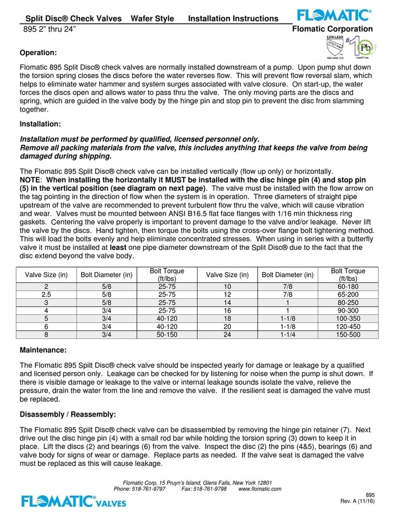
Model C501/CA501 Surge Arrestor Valve
MANUAL: C501 REV: 4
Note:
Place this Valve Product Manual in a safe place and with a person
responsible for the operation and maintenance of this valve.
Refer to Model and Serial Number above when ordering parts.
Serial Number: ___________________
Valve Model: ____________________
Size: ______
Serial Number: __________________
Low Pressure Pilot Setting : ______ PSI
Pressure Relief Pilot Setting: ______ PSI
System Pressure:_____ PSI
Installation Date: _________________
Name: __________________________

15 Pruyn's Island Drive
Glens Falls, New York 12801
Phone: (800) 833-2040
High Quality Valves Built to Last…
WWW.FLOMATIC.COM
Automatic Control Valve
Operation & Maintenance Manual
Model C501/CA501 Surge Arrestor Valve
MANUAL: C501 REV: 4
The Model 501 Surge Arrestor Valve controls over pressure and under pressure conditions. The pilot operated
control valve opens quickly to dissipate high surge pressure that exceeds a predetermined relief pressure setting
that can occur during pump start. The control valve also opens quickly for low surge pressure conditions that
can occur during normal pump shut down, electric power failure, and pump failure. The control valve will
continue to remain open following low surge pressure conditions to dissipate return pressure surges. The
control valve will close smoothly at an adjustable speed once system pressure has recovered within the normal
operating pressure zone above the low surge pilot setting or below the high surge pressure pilot setting.
Part List
1. Shut-Off Valve (3)
2. Strainer
3. Orifice
4. Pilot Valve (Over Pressure)
5. Pilot Valve (Under Pressure)
6. Air/Vacuum Valve
7. Accumulator
8. Needle Valve or Flow Control
9. Testcock
SHIPMENT:
When shipped, controls are usually mounted
on the main valve. If control subassemblies
are shipped separately, all connections are
tagged to insure correct assembly.
INSTALLATION:
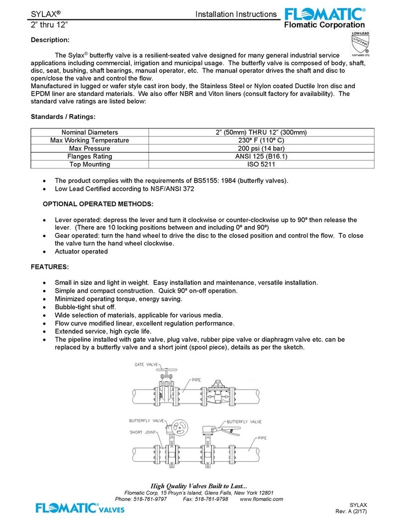
1. Model C501 is installed on a "Tee" from
the main line into atmosphere (waste).
2. Flush the pipeline before inserting the
valve.
3. Install the valve with the "arrow" on body
pointing in the direction of flow (waste).
4. Attach subassemblies to main valve if
necessary.
5. Allow enough clearance above valve for
removal of piston assembly.
STARTUP AND ADJUSTMENT:
1. Install pressure gauge to observe inlet pressure.
2. Model C501 requires manual closure to bring the valve on-line. Open Shut-Off Valve (1A) and close
Shut-Off Valve (1B). Re-open Shut-Off Valve (1B) after surge arrestor valve closes following step 4
or 5 to put the valve into automatic operation.
WARNING: Shut-Off Valve (1B) on downstream side must always be open for normal operation;
otherwise, main valve will not function.
3. Slowly open main line inlet side shut-off valve about 1/8 open and observe pressure gauge.

15 Pruyn's Island Drive
Glens Falls, New York 12801
Phone: (800) 833-2040
High Quality Valves Built to Last…
WWW.FLOMATIC.COM
Automatic Control Valve
Operation & Maintenance Manual
Model C501/CA501 Surge Arrestor Valve
MANUAL: C501 REV: 4
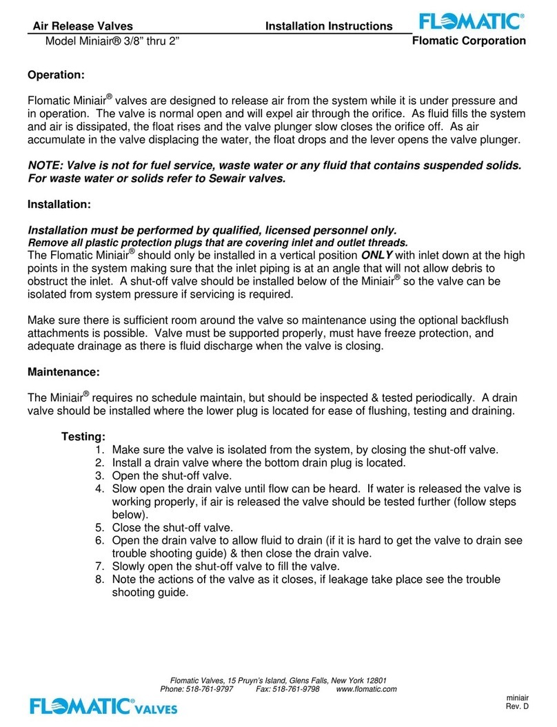
4. Open ¼” Test Cock (9) at top of valve. Re-close when water runs clear and absent of air bubbles. It
may take several cycles to bleed the Surge Arrestor power chamber properly.
5. Open the main line shut off valve (Gate or Butterfly valve) at the inlet (High Pressure) side of the
surge arrestor valve fully. If there is a main line shut-off valve at the outlet side of the surge arrestor
valve, open slowly. Water will flow through the open valve initially and decrease as the valve closes
gradually.
6. The controls of the Surge Arrestor Valve have been factory preset in accordance with the specified
operating conditions as provided on order placement. However, minor field adjustments may be
required as follows:
1. With pump running and developing the maximum pumping pressure:
a. If the Surge Arrestor Valve is open and passing water, turn the adjusting screw of
the Over Pressure Pilot (4) clockwise slowly until the main valve closes. Lock the
adjusting screw in this position.
b. If the Surge Arrestor Valve is closed, turn the adjusting screw of the Over Pressure
Pilot (4) counter-clockwise slowly until the valve opens and passes water; then
clockwise as noted in (a) above.
2. Shut down the pump and observe the pressure at which Under Pressure Pilot (5) starts to
open the Surge Arrestor Valve.To increase under pressure setting, turn the adjusting screw
of the Under Pressure Pilot (5) clockwise. To decrease under pressure setting, turn the
adjusting screw of the Under Pressure Pilot (5) counter-clockwise.
OPERATION:
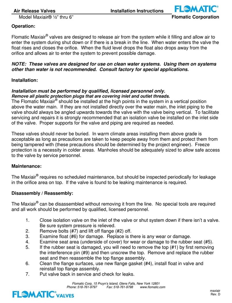
The over pressure pilot is a Normally Closed Model BPP Back Pressure Sustaining Pilot that remains closed
when system pressure is below the pilot set point. The under pressure pilot is a Normally Open Model PRR
Pressure Reducing Pilot that remains closed when the system pressure is above the pilot set point.
When the Model PRR Pressure Reducing Pilot (under pressure pilot), senses a subnormal pressure created by
the low-pressure portion of the surge wave (immediately after pump shut down or power failure), it causes the
main valve to open rapidly by exhausting control water from above the diaphragm of the main valve to an
accumulator. This insures that the main valve is open in anticipation of the returning high-pressure portion of the
surge wave to eliminate potential shock or hammer. When system pressure recovers within the normal
operating pressure zone above the Model PRR under pressure pilot set point, the main valve closes slowly at a
rate controlled by an adjustable flow control valve to prevent valve closing surges, and the accumulator will drain
in preparation for the next cycle.
When the Model BPP Back Pressure Sustaining Pilot (over pressure pilot), senses high pressure equal to or
above it’s set point, it causes the main valve to open rapidly by exhausting control water from above the
diaphragm of the main valve. When system pressure recovers within the normal operating pressure zone below
the Model BPP over pressure pilot set point, the main valve closes slowly at a rate controlled by an adjustable
flow control valve to prevent valve closing surges.

15 Pruyn's Island Drive
Glens Falls, New York 12801
Phone: (800) 833-2040
High Quality Valves Built to Last…
WWW.FLOMATIC.COM
Automatic Control Valve
Operation & Maintenance Manual
Model C501/CA501 Surge Arrestor Valve
MANUAL: C501 REV: 4
TROUBLE SHOOTING GUIDE:
PROBLEM: Valve opens and will not close.
CAUSE
1. Main valve is air bound.
2. Isolation valve at the inlet side of controls is closed.
3. Indicator stuffing box or sight glass is leaking (if
equipped).
4. Fouled orifice (or needle valve).
5. Fouled Y-strainer.
6. Damaged under pressure or over pressure pilot valve
seat.
7. Ruptured diaphragm in main valve.
8. Debris lodged under seat of main valve.
9. Worn seat seal and/or seat ring in main valve.
10. Incorrect adjustment of Under Pressure Pilot (set too
high).
11. Incorrect adjustment of Over Pressure Pilot (set too
low).
12. Leakage from one or more fittings in the controls.
13. Damaged o-ring stem seal.
CORRECTION
1. Open ¼” air bleeder located on top cover of valve to
release air.
2. Open isolation valve.
3. Tighten packing nut or replace packing seals.
4. Remove and clean orifice if required. Open needle valve
wide (counter clockwise) to flush seat. Return to original
setting after 4 or 5 seconds.
5. Disassemble, clean or replace screen.
6. Disassemble, clean and replace damaged parts.
7. Disassemble and replace diaphragm.
8. Disassemble and remove. Replace damaged parts.
9. Disassemble and replace damaged parts.
10. Turn Under Pressure Pilot adjusting screw counter-
clockwise slowly until valve resumes control and closes;
(refer to Section 6.2 for Under Pressure Pilot set point
adjustment).
11. Turn Over Pressure Pilot adjusting screw clockwise
slowly until valve resumes control and closes; (refer to
Section 6.1.a & 6.1.b for Over Pressure Pilot set point
adjustment).
12. Tighten or replace fitting.
13. Disassemble and replace o-ring.
PROBLEM: Valve is closed and will not open.
1. Incorrect adjustment of Over Pressure Pilot (set too
high).
2. Needle Valve open too far
3. Isolation valve at the outlet side of the controls is closed.
4. Fouled pilot valve(s)
5. Worn or eroded orifice (or needle valve seat).
1. Turn the Over Pressure Pilot adjusting screw counter-
clockwise slowly until the valve opens, then turn clockwise
untill the valve closes at the desired set point; (refer to
Section 6.1.a & 6.1.b for Over Pressure Pilot set point
adjustment).
2. Turn adjusting cap clockwise slowly until vavle opens
and then clockwise until valve re-closes
3. Open isolation valve.
4. Disassemble and clean, rebuild as necessary.
5. Replace orifice (or needle valve).
This manual suits for next models
1
Table of contents
Other Flomatic Control Unit manuals
Popular Control Unit manuals by other brands
G&D
G&D DP-HR-U Installation and operations
ZIEHL-ABEGG
ZIEHL-ABEGG UNIcon CKG-3RVE operating instructions
Ekinex
Ekinex EK-EB2-TP manual
Kohler
Kohler Mira Select B14C Installation and user guide
Bray
Bray FLOW-TEK Series Installation, operation and maintenance manual

Mitsubishi Electric
Mitsubishi Electric Q68AD-G user manual
Airwell
Airwell RCW-2 user manual
Allen-Bradley
Allen-Bradley 1771-OD Installation data
Beninca
Beninca BRAIN 24 operating instructions
Sennheiser
Sennheiser UUSB 8 instruction manual
Access
Access Flow2 User's manual & installation instructions
Cyfral
Cyfral CC-4000 Operating, Installation and Programming Manual
