Flomatic SYLAX User manual

SYLAX®Installation Instructions
2” thru 12” Flomatic Corporation
High Quality Valves Built to Last...
Flomatic Corp, 15 Pruyn’s Island, Glens Falls, New York 12801
Phone: 518-761-9797 Fax: 518-761-9798 www.flomatic.com
SYLAX
Rev: A (2/17)
Description:
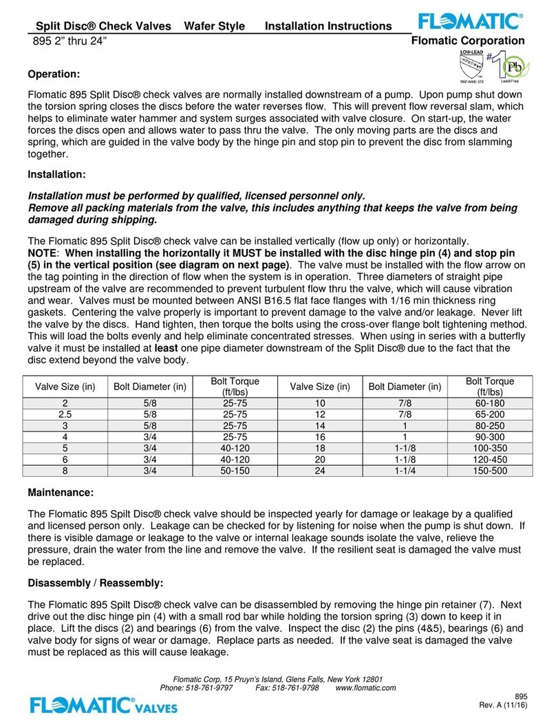
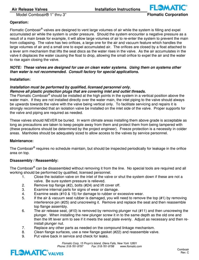
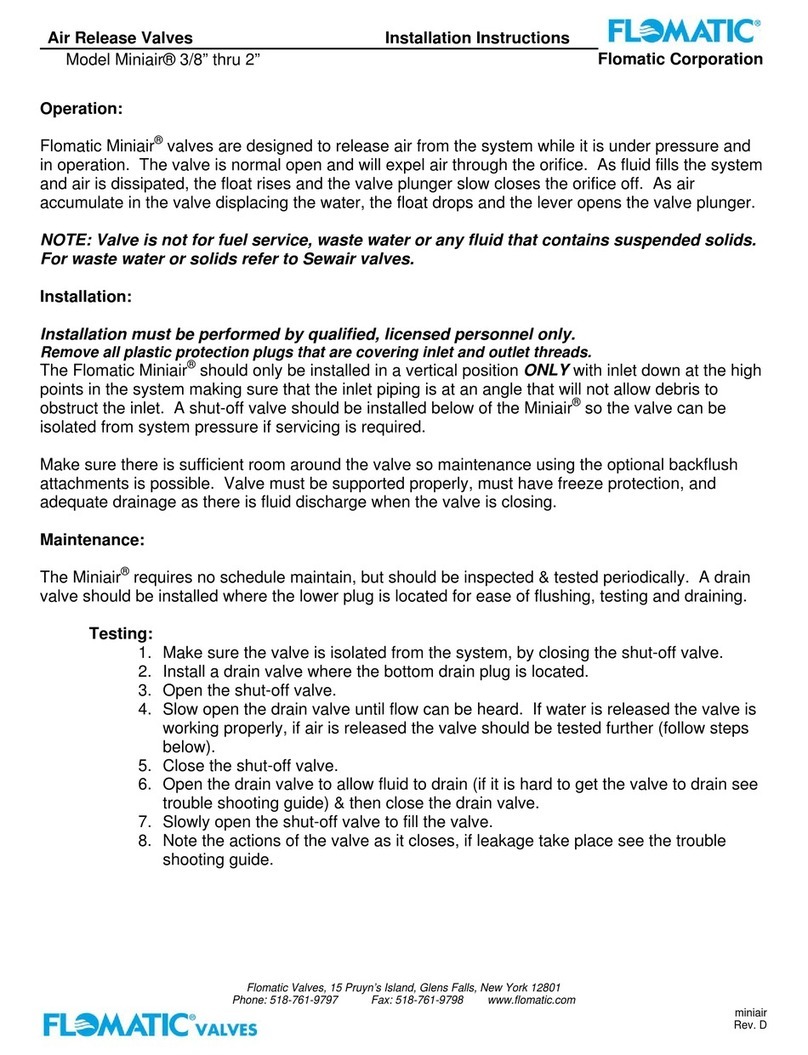
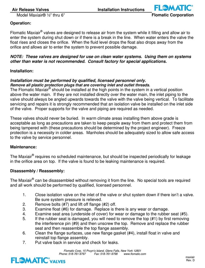
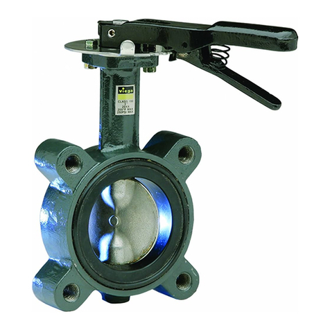
The Sylax®butterfly valve is a resilient-seated valve designed for many general industrial service
applications including commercial, irrigation and municipal usage. The butterfly valve is composed of body, shaft,
disc, seat, bushing, shaft bearings, manual operator, etc. The manual operator drives the shaft and disc to
open/close the valve and control the flow.
Manufactured in lugged or wafer style cast iron body, the Stainless Steel or Nylon coated Ductile Iron disc and
EPDM liner are standard materials. We also offer NBR and Viton liners (consult factory for availability). The
standard valve ratings are listed below:
Standards / Ratings:
Nominal Diameters 2” (50mm) THRU 12” (300mm)
Max Working Temperature 230º F (110º C)
Max Pressure 200 psi (14 bar)
Flanges Rating ANSI 125 (B16.1)
Top Mounting ISO 5211
The product complies with the requirements of BS5155: 1984 (butterfly valves).
Low Lead Certified according to NSF/ANSI 372
OPTIONAL OPERATED METHODS:
Lever operated: depress the lever and turn it clockwise or counter-clockwise up to 90º then release the
lever. (There are 10 locking positions between and including 0º and 90º)
Gear operated: turn the hand wheel to drive the disc to the closed position and control the flow. To close
the valve turn the hand wheel clockwise.
Actuator operated
FEATURES:
Small in size and light in weight. Easy installation and maintenance, versatile installation.
Simple and compact construction. Quick 90º on-off operation.
Minimized operating torque, energy saving.
Bubble-tight shut off.
Wide selection of materials, applicable for various media.
Flow curve modified linear, excellent regulation performance.
Extended service, high cycle life.
The pipeline installed with gate valve, plug valve, rubber pipe valve or diaphragm valve etc. can be
replaced by a butterfly valve and a short joint (spool piece), details as per the sketch.

SYLAX®Installation Instructions
2” thru 12” Flomatic Corporation
High Quality Valves Built to Last...
Flomatic Corp, 15 Pruyn’s Island, Glens Falls, New York 12801
Phone: 518-761-9797 Fax: 518-761-9798 www.flomatic.com
SYLAX
Rev: A (2/17)
SHIPMENT / STORAGE / INSTALATION:
Sylax®butterfly valves disc should be opened no more then 4 to 5 degrees during storage or
transportation. This is to protect the disc edge from damage.
Sylax®butterfly valves should be stored in a clean, dry place away from uv light.
Prior to installation verify:
That the Sylax®butterfly valve selected is correct for the application.
That all sealing surfaces are clean, and free from debris.
That all scale, debris, foreign materials are removed from piping system.
That valve operator (lever, gear or actuator) is properly secured to valve.
That Sylax®butterfly valve disc outside diameter is not greater than piping/flange inside diameter.
If it is valve will not open properly and you may “jam” disc inside piping/flange damaging valve
disc.
The Sylax®butterfly valve can be installed in any orientation in pipeline.
Flow through the Sylax®butterfly valve can be bi-directional.
Position of Sylax®butterfly valve in piping system should allow for ease of operation, maintenance and
removal.
Mounting wafer style Sylax®butterfly valves to the pipeline flanges can be done with either bolts or studs
that extend through both flanges
Mounting lug style Sylax®butterfly valves to the pipeline flanges should be done with bolts only. Studs
are not recommended.
During installation verify:
The piping alignment to Sylax®butterfly valve is correct.
The Sylax®butterfly valve disc is open partially inside the valve body. Disc should not be in full
closed position when tightening flanges. This allows rubber seal to self position for proper seal to
disc interaction.
A flange gasket is not used between the Sylax®butterfly valve and the pipe flange. The Sylax®
butterfly valve seat / liner flange face has a molded in o’ring which provides all the valve to flange
sealing necessary.
The Sylax®butterfly disc is interference free from piping components. While flange bolting is
finger tight, open disc slowly to check for interference. If no interference return disc to partial
open and finish tightening flange bolts in a crisscross pattern. If interference occurs check for
piping misalignment. After realigning piping flanges recheck for interference.
After installation Sylax®butterfly valve disc should be in open position for initial system pressure testing.
Recommended routine inspection checks should include:
Verification by visual inspection that valve seat and flange sealing surfaces are in good condition.
Verification that the valve operator is in working condition.
After inspection/maintenance verify that valve is opening and closing smoothly.
After inspection/maintenance verify that valve is leak tight in closed position.
Wafer and lug style butterfly valves provide the same working performance. However the lug style, only
can be used for “bi-directional dead end” service, however, pressure rating may be de-rated.
NOTE: for size and quantities of bolts see table
1 BODY
2 DISC
3 SHAFT
4 LINER
5 CIRCLIP
6 O’RING
7 BUSHING
8 SAFETYBUSHING
9 UPPER BUSHING
10 LOWER BUSHING
11 LEVER ASSEMBLY

SYLAX®Installation Instructions
2” thru 12” Flomatic Corporation
High Quality Valves Built to Last...
Flomatic Corp, 15 Pruyn’s Island, Glens Falls, New York 12801
Phone: 518-761-9797 Fax: 518-761-9798 www.flomatic.com
SYLAX
Rev: A (2/17)
REMOVING VALVE FROM SYSTEM:
WARNING !
Loosening the bolts on a pressurized valve/system can cause the valve to shift and release
uncontrolled pipeline fluid. This will cause personal injury and/or pipeline damage.
Relieve the pressure from the system and make sure to drain the pipeline before loosening valve bolting.
Close the Sylax®butterfly valve disc before removing from between the pipe flanges.
If the Sylax®butterfly valve has an electric actuator make sure to turn off and lock out the power
before removing or servicing.
If the actuator is powered, disconnect and lock out any electric, pneumatic or hydraulics to prevent injury
and/or accidental operation.
Support the Sylax®butterfly valve, remove the bolts completely then remove the Sylax®butterfly valve
from the pipeline.
Do not lift by the stem – this will damage the Sylax®butterfly valve and void the warranty.
TROUBLE SHOOTING:
PROBLEM REASON POSSIBLE SOLUTION
Valve does not fully close Debris wedged between disc and
seal or stop is not adjusted correctly
Open valve to flush out debris or
adjust the close stop
Leakage at sealing surface Seat damaged, disc damaged or
dirt between disc and seat
Replace seat or disc, clean the
sealing surface
Leakage at the shaft The seat shaft hole damaged, or O-
ring damaged
Replace seat or O-ring
Leakage at flange end The bolt did not contact tightly, or
not uniform, or seat damaged
Tighten bolts or replace the seat.
Warning: Working pressure, temperature, media must match valve capability or valve/piping
damage can occur.
Working pressure must not exceed valve maximum pressure rating.
Temperature must not exceed maximum temperature rating.
Media must be compatible with body, seat, seals and disc material.
Flomatic Valves is not responsible for the loss caused by the usage beyond the valve capabilities.
SIZE & QUANTITIES OF BOLTS FOR INSTALLATION:
SIZE Flange 125# / 150#
in mm QTY Bolt ǾBolt Length Torque (ft/lbs)
2-1/2 65 4 ⅝2-1/2 25-75
3 80 4 ⅝2-1/2 25-75
4 100 8 ⅝3 30-90
5 125 8 ¾ 3 30-90
6 150 8 ¾ 3-1/4 30-90
8 200 8 ¾ 3-1/2 40-120
10 250 12 ⅞3-3/4 45-150
12 300 12 ⅞3-3/4 65-200
Limited One Year Warranty: Flomatic valves are guaranteed against defects of material or workmanship when used for the
services recommended. If, in any recommended service a defect develops due to material or workmanship, and the device is
returned, freight prepaid, to Flomatic Corporation within 12 months from date of purchase, it will be repaired or replaced free of
charge. Flomatic Corporations’ liability shall be limited to our agreement to repair or replacement of valve only.©2017
Table of contents
Other Flomatic Control Unit manuals
Popular Control Unit manuals by other brands
Allen-Bradley
Allen-Bradley POINT I/O 1734-ADN installation instructions
Honeywell
Honeywell LYNX TOUCH 2 Series installation guide

Gentec
Gentec TFT3500 installation manual
Viega
Viega ProPress 22074 Product instructions

WAGO
WAGO 750-494 Series manual

Telit Wireless Solutions
Telit Wireless Solutions JF2 Hardware user's guide
