floorex SATELLITE 650 MkII Troubleshooting guide
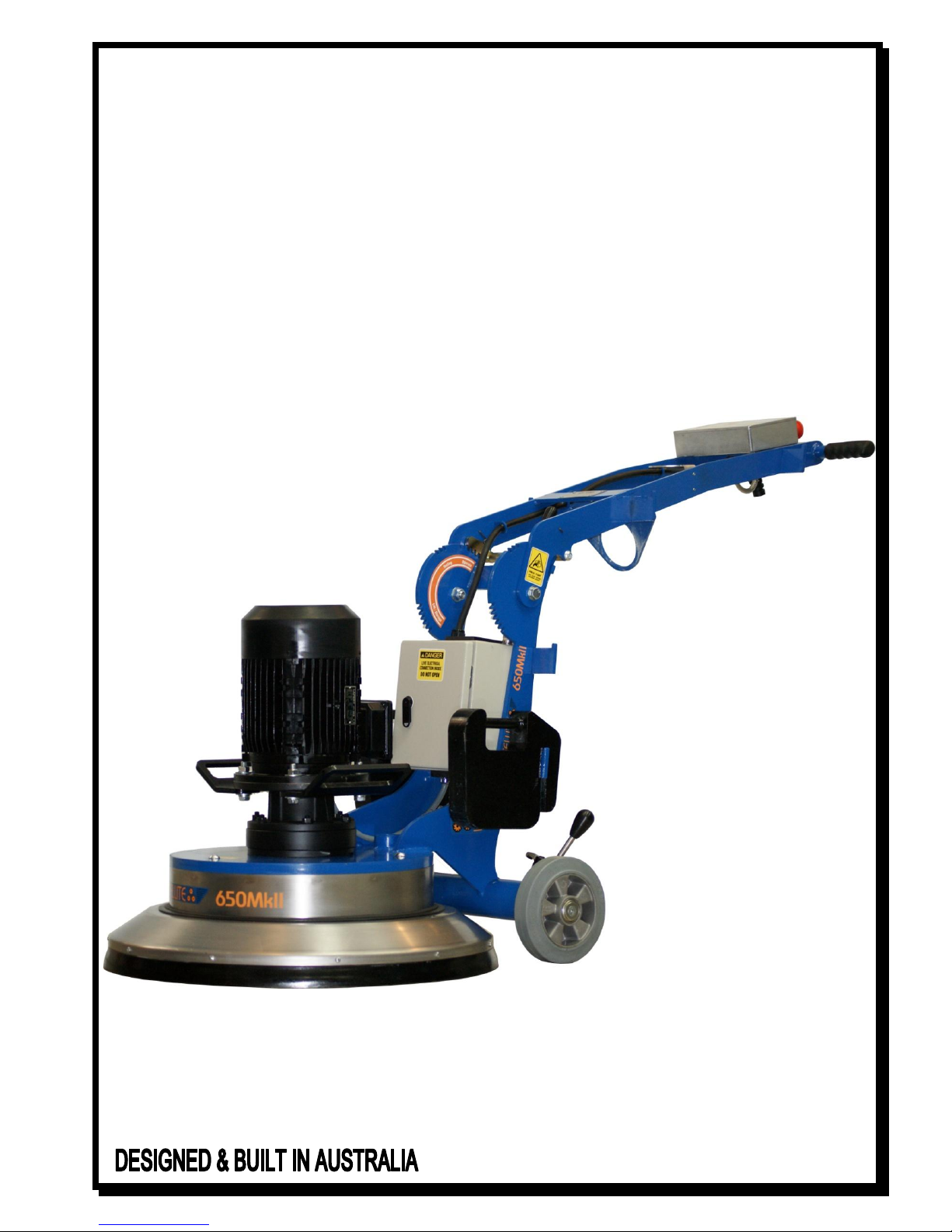
SATELLITE 650 MkII
SAFETY & OPERATORS MANUAL
& PARTS LISTING
20-11-09

SATELLITE 650 MkII
1800 FLOOREX
1800 356 673
Page 1
Table of contents
PAGE 1. Table of contents
PAGE 2. Safety instructions
PAGE 3. Operating instructions
PAGE 4. Operating instructions cont...
PAGE 5. Tooling Removal & Magnetic Plugs
PAGE 6. Axle height adjustment
PAGE 7. Electrical safety
PAGE 8. Problem solving
PAGE 9. Diamond plugs
PAGE 10. 10 & 7” Satellite disks
PAGE 11. 5” Satellite disks
PAGE 12. Main parts breakdown
PAGE 13. Handle Breakdown
PAGE 14. Disk Breakdown
PAGE 15. Parts listing
PAGE 16. Parts listing
PAGE 17. Wiring Diagram

SATELLITE 650 MkII
1800 FLOOREX
1800 356 673
Page 2
Safety instructions
01. Read and understand the instructions on the machine and in this manual and engine manual (if applicable).
Different models may have different parts and controls.
02. Equipment should only be operated by trained personnel, in good physical condition and mental health (not
fatigued). The operator and maintenance personnel must physically be able to handle the bulk weight and power of
this machine.
03. The SATELLITE 650 MkII must only be used according to the instructions given in this manual. Any other work
methods or practices could result in injury or death
04. The SATELLITE 650 MkII has different positions in which the handle can be locked into. These are described in this
manual as ‘OPERATE’, ‘TOOLING REMOVAL’ and LIFT/STORAGE’. See the at the end of this manual for diagrams of
these positions. When to use and when not to use these positions is described throughout this manual
05. This is a one person machine. Maintain a safe operating distance to other personnel. Remember ‘one machine, one
operator’.
06. This equipment is intended for commercial use.
07. For the operators’ safety and the safety of others, always keep all guards and shrouds in place.
08. Never start or run machine when it is unattended.
09. Check for wear on magnetic plugs every 3 hours of use
10. This machine is only intended for use on floor surfaces such as concrete, terrazzo and other hard floor surfaces.
11. The handle height is adjustable with different positions for operator comfort. These positions are shown next to the
locking mechanism as ‘OPERATE’. The SATELLITE 650 must never be started or used with the handle in any other
position other than the ‘OPERATE’ positions’
12. Never attempt to adjust the handle position when the machine is in operation.
13. Never start or run machine with the handle folded or when disk(s) are not in contact with the surface.
14. Do not lend or rent machine without the operating and safety instructions for the machine (and the engine, if
applicable).
15. Wear clothing suitable for the job and for the work place including, safety shoes, hard hat, hearing protection, non
fogging vented safety goggles, and dust mask suitable for dust.
16. Keep body parts or any loose clothing away from moving parts. Failure to comply could result in bodily injury.
17. Do not modify machine in any way. Only use genuine SATELLITE parts and accessories.
18. Repairs should be performed by qualified persons only.
19. Ensure parts have stopped moving and disconnect power or spark plug when servicing or changing blades or
accessories.
20. Never operate machine in rain or if heavy moisture is present.
21. Petrol is extremely flammable and poisonous. Petrol should only be dispensed in well ventilated areas, and only
when engine is cool.
22. WARNING! POISONOUS EXHAUST GASES. Do not operate petrol powered equipment, including generators,
without adequate ventilation. Carbon monoxide is and invisible odorless gas that can harm or can kill.

SATELLITE 650 MkII
1800 FLOOREX
1800 356 673
Page 3
Operating Instructions
01. Wear clothes suitable for the job and for the work place including, safety shoes, hard hat, hearing protection, non-
fogging vented safety goggles, and dust respirator suitable for dust.
02. The SATELLITE 650 MkII must only be used according to the instructions given in this manual. Any other work
methods or practices could result in injury or death
03. WARNING! Disconnect power before moving the Handle to the ‘TOOL REMOVAL’ or ‘LIFT’ positions.
04. WARNING! POISONOUS EXHAUST GASES. Do not operate petrol powered equipment, including generators, without
adequate ventilation. Carbon monoxide is and invisible odorless gas that can harm or can kill.
05. Be sure all equipment is tested and tagged prior to use on any job.
06. Inspect entire area to be ground before grinding and remove any bolts or concrete nails (etc) that could damage
tooling or the machine and which could cause a hazardous situation.
07. Ensure there are no obstacles or existing structures that could present a hazard to the operator. If so, take necessary
action to eliminate the hazard.
08. Fold handle to the ‘TOOLING’ position and ensure it is locked in place, then tilt machine back so handle is resting
along the floor.
09. The machine takes a set of three (3) tools. Be sure the tools are of even height.
10. Install appropriate diamond tooling or other available tooling into the machine. Only use genuine SATELLITE tooling.
Failure to comply could result in bodily injury.
11. Tilt machine back onto the disk and put the handle in one of the ‘OPERATE’ positions. Adjust the position to one that
you are comfortable with.
12. Never attempt to adjust the handle position when the machine is in operation.
13. Connect machine to suitable power outlet. Only use heavy duty power lead suitable for high current use (preferably
2.5mm² cable), no longer than 15 meters.
14. If no power is available within the specified distance, have a qualified person install a suitable power outlet closer to
your work. Alternatively use 4mm² cable for up to 40 meters.
15. Connect a suitable dust extractor to the machine via a 38 or 50mm flexible hose. The machine is designed to take
the standard 50mm hose ends to make connection of dust extractors easy and hassle free.
16. Keep machine clear of drainage pits, grates, steps or major lips or such hazard. Failure to comply could result in
bodily injury and or could damage the machine or property.
17. Ensure machine is on a level surface and handle is in one of the ‘OPERATE’ positions
18. This machine is designed to operate with the wheels in contact with the floor at all times. Do not operate with
wheels off the floor.
19. The SATELLITE 650 MkII has axle height adjustment to make it easy to adjust the machine so it doesn’t cause fatigue
on the operator. To set axle height, adjust the axle height leaver to the vertical position, or midpoint. This is a good
starting point. After initial operation the axle can be adjusted. The axle lever must be set as far back (toward
operator) as possible without creating excess force on the operator during operation. See 24 below.
20. Switch on the dust extractor.

SATELLITE 650 MkII
1800 FLOOREX
1800 356 673
Page 4
Operating Instructions cont…
21. Hold the handles firmly and switch the SATELLITE 650 MkII on by pushing the green button.
22. The controls on the SAT650 MkII include an over load device. It is there to protect the controls and motor from
irreparable damage. If it trips it indicates a problem. (i.e.; undersize power lead or poor power to your power
supply). Refer earlier in this section for recommendations on power leads. Rectify the problem or decrease load on
the Satellite 650 by using tooling with more surface area, or place weights supplied on the brackets on handle for
this purpose.
23. Continuing to use the SATELLITE 650 when constant tripping occurs, VOIDS THE WARRANTY.
24. Do not attempt to make any adjustments while the machine is in operation. Any adjustments must only be
performed when machine is stopped and power disconnected.
25. In the event of the machine pulling to one side all the time; adjust the axle height to obtain the best result. (See
‘AXLE HEIGHT’). This machine is designed to operate with the wheels in contact with the floor at all times. Do not
operate with wheels off the floor.
26. After a few minutes of grinding check the wear of the diamond tooling. This will pay handsomely if the diamonds are
wearing out fast due to soft concrete / abrasive concrete. There is a wide range of diamonds available to suit every
need. See Section ‘DIAMOND TOOLING SELECTION GUIDE’.
27. Check for wear on magnetic plugs every 3 hours of use
28. See Section ‘PROBLEM SOLVING’ for tips on how to grind faster on tough concrete and how other problems can be
rectified.
29. WARNING! As with any diamond tooling, breathable silica may be generated by use and maintenance of this
machine. Silica can cause severe and permanent lung damage, cancer, and or other serious diseases. Do not breathe
the dust. Do not rely on your sight or smell to determine if dust is in the air. Silica may be in the air without a visible
dust cloud. If air monitoring for silica is not provided by your employer at your work site, you must wear appropriate
respiratory protection when operating or maintaining this equipment. Consult your employer for proper respiratory
protection.

SATELLITE 650 MkII
1800 FLOOREX
1800 356 673
Page 5
Tooling Removal & Magnetic Plugs
01. To remove tooling from the magnetic plugs, Tilt the machine as per instructions in the operating instructions and
grasp hold of the diamond disk and give it a sharp pull away from the main black disk.
02. To remove the plug from the main black disk strike the black disk beside the taper insert as shown below.
03.
04. The magnetic plugs must be cleaned every time the insert is removed.
05. Ensure the insert is not worn more than 30% through where the blade runs on the insert
06. Clean out the hole in the plug where the inert goes. Ensure there are no particles or pieces of steel (such as staples
ETC).
07. Refit the insert on the blade and put the two onto the plug ensuring the insert goes completely into the plug

SATELLITE 650 MkII
1800 FLOOREX
1800 356 673
Page 6
Axle height adjustment
01. This machine is designed to operate with the wheels in contact with the floor at all times. Do not operate with
wheels off the floor.
02. The axle lever must be set as far back (toward operator) as possible without creating excess force on the operator
during operation.

SATELLITE 650 MkII
1800 FLOOREX
1800 356 673
Page 7
Electrical safety
01. All electrical maintenance and repairs are to be carried out by qualified persons only.
02. CAUTION - Line terminals may be alive when main switch is in the off position. Disconnect the machine completely
before performing any maintenance or repairs.
03. WARNING - DO NOT operate the machine with any electrical panels open.
04. WARNING - The controls on the SAT650 MkII include an over load device. It is there to protect the controls and
motor from irreparable damage. If it trips it indicates a problem. (i.e.; undersize power lead or poor power to your
power supply). Refer earlier in this manual for recommendations on power leads. Rectify the problem or decrease
load on the Satellite 650 by using tooling with more surface area, or place weights supplied on the brackets on
handle for this purpose.
05. Continuing to use the SATELLITE 650 when constant tripping occurs, VOIDS THE WARRANTY!
06. Never operate machine in the rain or if heavy moisture is present.
07. The overload is there to protect you and the machine from harm. DO NOT bypass or adjust the over load in any way.
If it is faulty, only replace with original part that is identical to the faulty one.
08. Never bypass over current devices in this machine.
09. Never connect or disconnect power cables with voltage present or while under load.
10. Disconnect all power connections and observe lock out / tag out procedures before attempting to carry out any
maintenance or repair on any equipment.
11. Avoid any contact with any rotating parts or driven parts.
12. Never use equipment that has not been tested and tagged (including cords).
13. Before connecting the machine to power, check the condition of all power leads and cables on, or used in
conjunction with the machine. DO NOT USE it if any faults, cuts, wear marks, etc… Get qualified persons to repair
and re-tag it as required by regulations in your country.
14. Connect machine to suitable power outlet. Only use heavy duty power lead suitable for high current use (preferably
2.5 mm2 cable), no longer than 15 meters.
15. If no power is available within the specified distance have a qualified person install a suitable power outlet closer to
your work. Alternatively use 4 mm² cable for up to 40 meters.
SATELLITE 650 MkII
1800 FLOOREX
1800 356 673
Page 8
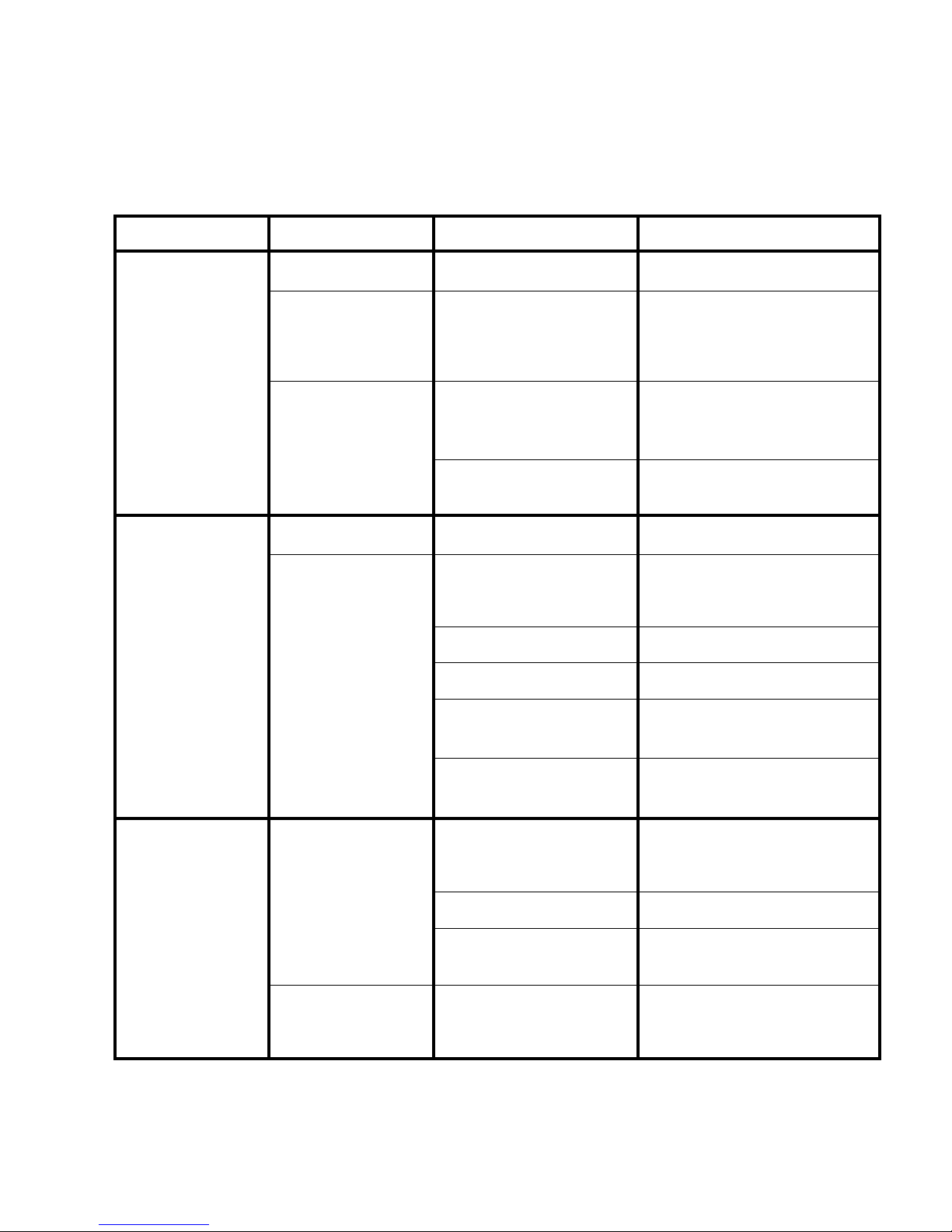
Problem solving
Diamond Grinding has many variables. When you understand some of these, you can solve
a lot of problems without a lot of bother and expense.
NOTE: THIS IS A GUIDE ONLY
PROBLEM
CAUSE
REMEDY
EXPLAINATION
Machine will not start
/ run.
No power is present at
cable end.
Check the power is present
with another tool.
Using another tool confirms power is
present
Machine is trying to start
on glue or other sticky
substance.
Clear a patch with a scraper
and grind into the glue a little
at a time.
This means it only tackles a small
amount of glue at a time and keeps
the glue residue coated with dust,
preventing glue sticking and building
up on the diamonds.
Power lead is too small
in capacity or too long.
Upgrade the power lead to
2.5mm² (15meters max) or
4mm² (40 meters max).
The long / small capacity cable is too
restrictive and can’t allow enough
power through for the machine to
start / run properly.
Use weight on the handle.
The weight on the handle reduces the
load on the machine thus reducing
the current.
Machine is not
grinding at all.
No blades / accessories
in unit.
Fit blades. Note; check wear on
machine.
Very hard concrete or
glazed topping on
concrete.
Turn dust extractor down /
restrict flow. Only just control
the dust from escaping.
The extra dust accumulating on the
floor acts as an abrasive between the
segments and the floor thus exposing
the diamonds better.
Place river sand or cement on
the floor.
The sand is an abrasive as described
above.
Use softer grade of diamond
tooling.
The softer grade will expose the
diamonds better.
Use coarser diamond tooling.
The coarser diamond tooling can get
through hard toppings without
wearing out the diamonds too fast.
Reverse the rotation of the
machine (switch on the bottom
of the motor box)
The tooling exposes the diamonds
when reversed. This works best when
using plugs.
The diamonds are
wearing out too fast.
The concrete is:
*Soft
*Abrasive
*Rain Damaged
*A rough finish (Scarified
or shot blasted).
Use a powerful dust extractor
to remove as much dust as
possible.
The dust, as described acts as an
abrasive between the segments
exposing the diamonds prematurely,
wasting them.
Use harder diamond matrix.
The harder segments don’t expose as
easily.
Use tooling with more
segments or area² of segment.
The tooling with more segments or
area² doesn’t have the same weight
on them, reducing wear.
The diamonds are too
soft or too few.
Use weights on the handle
This reduces the weight on the
diamonds thus reducing the wear on
them.

SATELLITE 650 MkII
1800 FLOOREX
1800 356 673
Page 9
Diamond plugs
PART No.
DESCRIPTION
GRIT
SEG
COLOUR
CONTRACTOR RANGE
2PDB 30/40
Soft Bond –Hard Concrete Only
30/40
50mm
YELLOW
4PDB 30/40
Hard Bond –Soft/Medium Concrete, for production grinding
30/40
50mm
GREEN
4PDB 16
Hard Bond –Med Concrete –Coarse Grade, fast grinding, epoxies etc.
16
50mm
GREEN
PREMIUM RANGE –LONG LASTING
1P3DT 30/40
Super Soft Bond Turbo Plug - for very hard concrete - 3 segment
30/40
3
BROWN
2PDT 16
Super Soft Bond Turbo Plug - 16# coarse grade - for aggressive removal
16
6
GREY
2PDT 30/40
Soft Bond Turbo Plug –Aggressive Removal of glues etc, for hard concrete
30/40
6
YELLOW
3PD5A 30/40
Medium Bond 5 segment Arrow Turbo Plug - Aggressive removal of glues etc
30/40
5
DARK BLUE
4PDT 16
Hard Bond Turbo Plug 16# coarse grade for aggressive removal
16
6
BLACK
4PDT 30/40
Hard Bond Turbo Plug 6 segment, aggressive removal of glues and coatings
30/40
6
ORANGE
4P3DT 30/40
Hard Bond Turbo Plug 3 segment, Extra aggressive removal of glues
30/40
3
WHITE
PCD-4100-2B
DINA-SOR Stripping Plug with PCD Segments.
PCD
4
PURPLE
SP-50-2PCD
Stripper PCD Plug
PCD
3
PURPLE
2PD 30/40
Soft Bond –Hard Concrete Only
30/40
50mm
YELLOW
4PD 30/40
Hard Bond –Soft / Medium Concrete
30/40
50mm
BLUE
4PD 16
Hard Bond –Medium Concrete, Coarse Grade, Fast Removal of epoxies
16
50mm
SILVER
4PD 120
Hard Bond –Soft Medium Concrete –Polishing Grade
120
50mm
RED
4PD 240
Hard Bond –Soft Medium Concrete –Polishing Grade
240
50mm
BLUE
4PD 600
Hard Bond –Soft Medium Concrete –Polishing Grade
600
50mm
BLUE
4PD 1200
Hard Bond –Soft Medium Concrete –Polishing Grade
1200
50mm
BLUE
4PD 3000
Hard Bond –Soft Medium Concrete –Polishing Grade
3000
50mm
BLUE

SATELLITE 650 MkII
1800 FLOOREX
1800 356 673
Page 10
10” Satellite disks
PART No.
DESCRIPTION
GRIT
SEG
COLOUR
10” PREMIUM RANGE –LONG LASTING
CG 10BLT-99
10" Super Premium - Extra Long Life, soft/med concrete
30
18
BLUE
CG 10BRT-60
10" Super Premium - Extra Soft matrix for very hard concrete
30
6
BROWN
CG 10WHT-90
10" Super Premium - Glue Removal, soft/med concrete
30
9
WHITE
CG 10BKT-33
10" X 3 Long / 3 Short Segments Super Premium - Aggressive, Glue Removal
30
6
BLACK
CG 10ORT-30
10" Super Premium - Extra Aggressive, med/hard concrete
30
3
ORANGE
CG 10RET-09
10" Super Premium - Medium Bond - For Fine Finish, for polishing
150
9
RED
7” Satellite disks
PART No.
DESCRIPTION
GRIT
SEG
COLOUR
7” CONTRACTOR RANGE
BCGF 720 DTY
Diamond Wheel - 12 Segment - For Very Hard Concrete
30/60
12
YELLOW
BCGF 725 DTG
Diamond Wheel –12 Segment –Glue Removal, hard concrete
30/60
12
GREEN
BCGF 728 DTS
Diamond Wheel –12 Segment –Aggressive 25# for epoxy removal
25
12
SILVER
BCGF 745 DTG
Diamond Wheel –18 Segment –Standard Grinding Wheel
30/60
18
GREEN
BCGF 735 DTG
Diamond Wheel –24 Segment –Fine Finish, Soft/Medium Concrete
30/60
24
GREEN
7” PREMIUM RANGE –LONG LASTING
CGF 7BTD
Super Premium Diamond Wheel, Extra Long Life, soft-medium concrete
30
18
BLUE
CGF 7CTD
Super Premium Diamond Wheel, Aggressive Removal , soft-med concrete
30
9
WHITE
CGF 7RTD
Super Premium Diamond Wheel, 150# Fine Grade, Medium Bond
150
9
RED
CGF 7STD
Super Premium Diamond Wheel, Extra Soft Bond, for very hard concrete
30
6
BROWN
CGF 7YTD
Super Premium Diamond Wheel, Aggressive Removal, soft bond, hard concrete
30
9
YELLOW
CGF 73TD
Super Premium Diamond Wheel, Extra Aggressive, Med - Hard Concrete
30
3
ORANGE
CGF 76PCD
PCD Diamond Wheel - Extra Aggressive for heavy removal of coatings & glues
PCD
6
PURPLE
CGF 725 DTG
Diamond Wheel –12 Segment –Glue Removal, hard concrete
30/50
12
GOLD
CGF 745 DTB
Diamond Wheel –18 Segment –Standard Grinding
30/50
18
BLUE
CGF 735 DTG
Diamond Wheel –24 Segment –Fine Finish
30/50
24
GOLD
CGF 7150 DTG
Diamond Wheel –18 Segment –150# Fine Grade
150
18
RED

SATELLITE 650 MkII
1800 FLOOREX
1800 356 673
Page 11
5” Satellite disks
PART No.
DESCRIPTION
GRIT
SEG
COLOUR
5” CONTRACTOR RANGE
BCG 420 DTY
5” Diamond Wheel – 9 Segment –Hard Concrete, coating removal
30/60
9
YELLOW
BCG 425 DTS
5” Diamond Wheel – 9 Segment –Coarse Grade 25#
25
9
SILVER
BCG 4445 DTG
4.5” Diamond Wheel – 9 Segment –Medium Concrete
30/60
9
GREEN
BCG 445 DTG
5” Diamond Wheel – 9 Segment –Medium Concrete
30/60
9
GREEN
BCG 455 DTG
5” Diamond Wheel – 18 Segment –Fine Finish, soft/medium concrete.
30/60
18
GREEN
BCG 4515 DTR
5” Diamond Wheel – 18 Segment, Fine Grade 150#
150
18
GREEN
5” PREMIUM RANGE
CG 445 DTG
5” Diamond Wheel – 9 Segment –Aggressive removal
30/60
9
GOLD
CG 455 DTG
5” Diamond Wheel – 18 Segment –Fine Finish, Hard Concrete
30/60
18
GOLD
CG 4515 DTR
5” Diamond Wheel – 18 Segment –Fine Grade 150#
150
18
RED
SATELLITE 650 MkII
1800 FLOOREX
1800 356 673
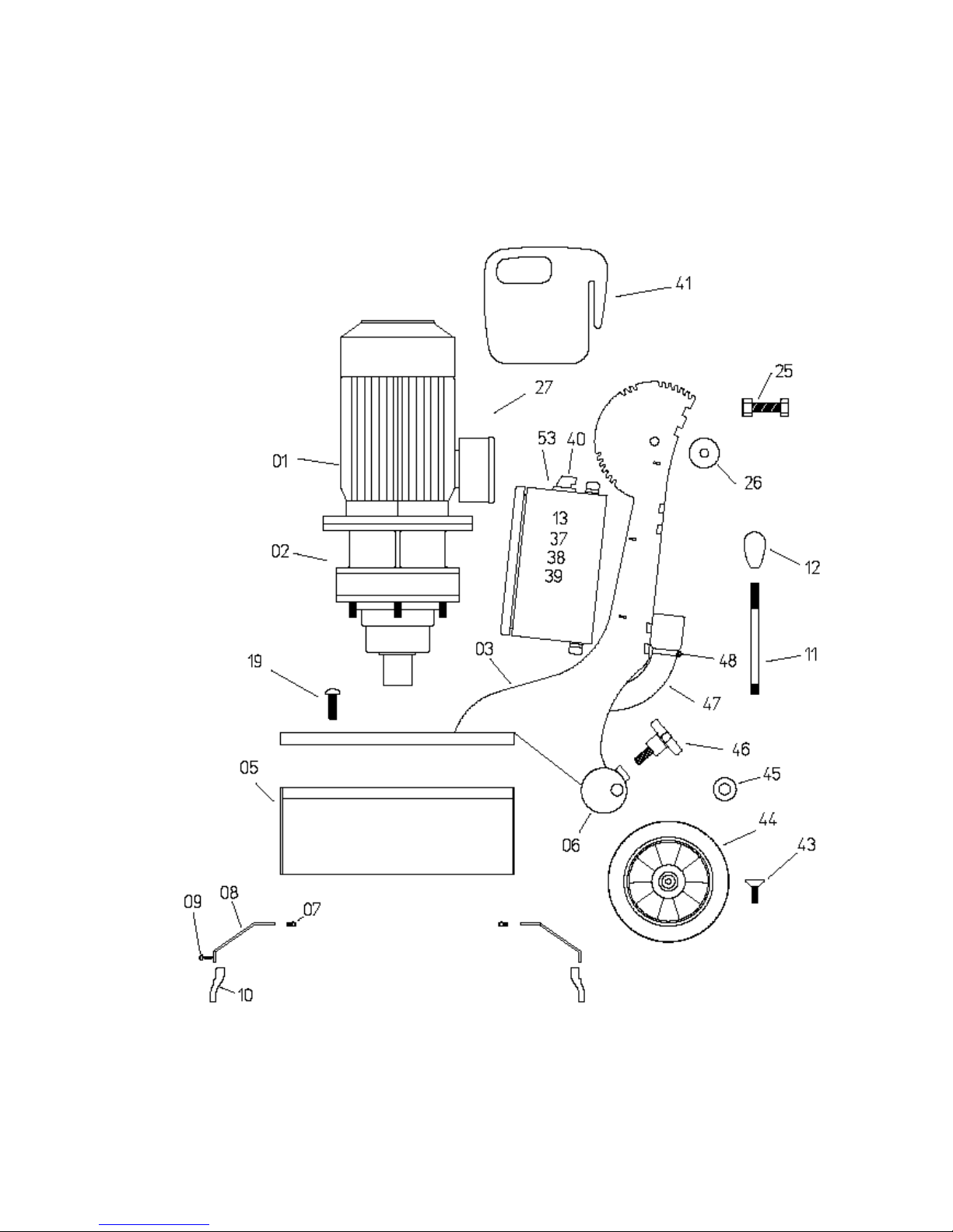
Page 12
Main parts breakdown
SATELLITE 650 MkII
1800 FLOOREX
1800 356 673
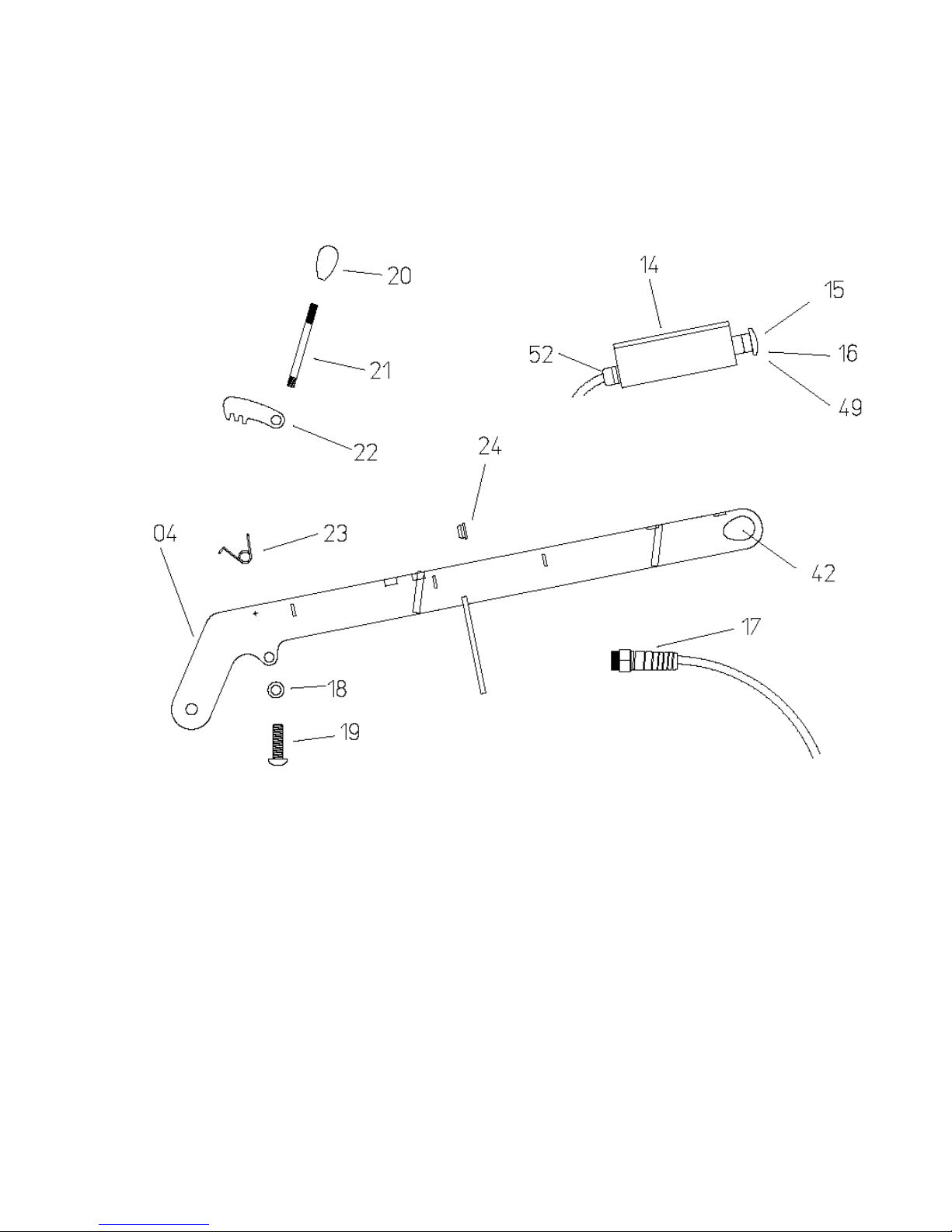
Page 13
Handle breakdown

SATELLITE 650 MkII
1800 FLOOREX
1800 356 673
Page 14
Disk breakdown

SATELLITE 650 MkII
1800 FLOOREX
1800 356 673
Page 15
Parts Listing
Item
QTY
Part No.
Description
01
1
SAT-650201
Motor 4kw
02
1
SAT-650202
Transmission 11:1
03
1
SAT-650203
Main Chassis
04
1
SAT-650204
Handle
05
1
SAT-650205
Shroud upper
06
1
SAT-650206
Axle removable
07
1
SAT-650207
Shroud seal
08
1
SAT-650208
Shroud floating
09
9
SAT-650209
Shroud screw
10
1
SAT-650210
Shroud polyurethane
11
1
SAT-650211
Axle lever arm
12
1
SAT-650212
Axle lever knob
13
1
SAT-650213
Overload TE
14
1
SAT-650214
Electrical box complete
15
1
SAT-650215
Emergency stop button complete
16
1
SAT-650216
Start stop Switch complete
17
1
SAT-650217
Cable gland with support
18
2
SAT-650218
Ratchet lock spacer .55
19
2
SAT-650219
Socket dome head M12 x 50
20
1
SAT-650220
Handle lever knob
21
1
SAT-650221
handle lever arm
22
1
SAT-650222
handle lock mechanism
23
1
SAT-650223 L
Handle lock Spring L
23
1
SAT-650223 R
Handle lock Spring R
24
7
SAT-650224
Rubber Grommet
25
2
SAT-650225
Bolt and lock nut M14 x 40
26
2
SAT-650226
Handle Spacer .55

SATELLITE 650 MkII
1800 FLOOREX
1800 356 673
Page 16
Parts Listing
Item
QTY
Part No.
Description
27
1
SAT-650227
Motor terminal box
28
1
SAT-650228
Drive Hub
29
3
SAT-650229
Coupling Rubber
30
6
SAT-650230
Torque rubber
31
6
SAT-650231
Coupling rubber bolt
32
3
SAT-650232
Taper insert retaining ring
33
3
SAT-650233
Taper insert incl. No. 32
34
3
SAT-650234
Magnetic plug MkII incl. No.35
35
3
SAT-650235
Magnetic plug MkII retainer
36
1
SAT-650236
Main disk
37
1
SAT-650237
Main Box
38
1
SAT-650238
VSD 4kw
39
1
SAT-650239
Base Plate
40
1
SAT-650240
Reverse Switch
41
2
SAT-650241
Weight MkII
42
2
SAT-650242
Handle grip
43
2
SAT-650243
Wheel Retaining bolt
44
2
SAT-650244
Wheel
45
8
SAT-650245
Wheel spacer
46
2
SAT-650246
Ratchet Handle M12 Male
47
1
SAT-650247
Hose 50mm Flex
48
2
SAT-650248
Hose clamp 50mm S/S
49
1
SAT-650249
silicone boot Start stop switch
50
1
SAT-650250
Spare
51
1
SAT-650251
Spare
52
2
SAT-650252
Nylon Gland M20
53
1
SAT 650253
Disconnect Switch
SATELLITE 650 MkII
1800 FLOOREX
1800 356 673
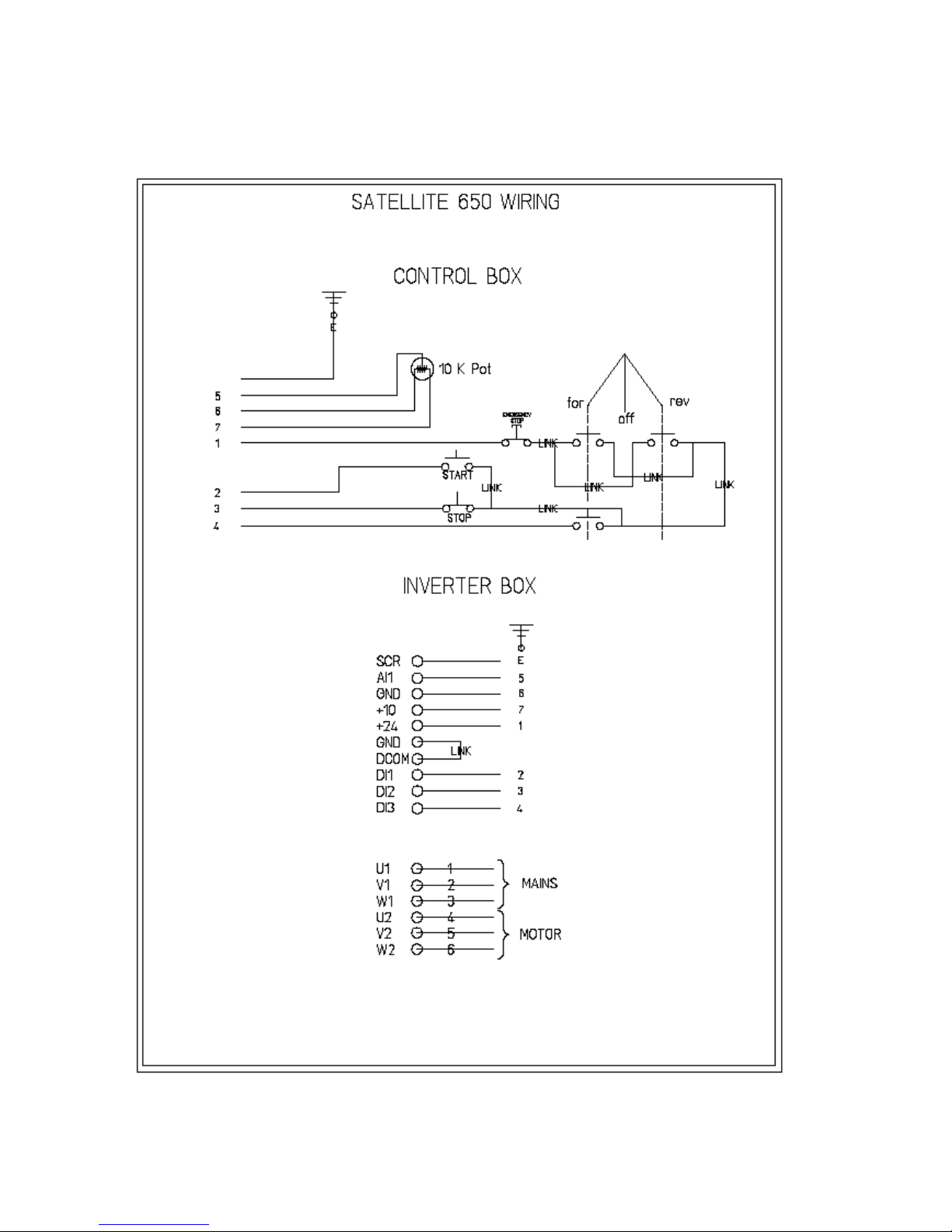
Page 17
Wiring Diagram
Table of contents
Other floorex Grinder manuals


