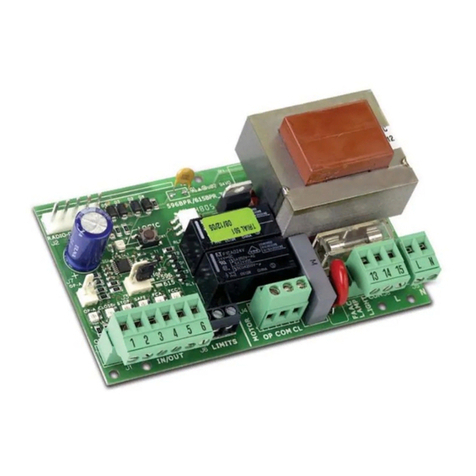
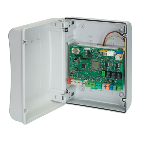
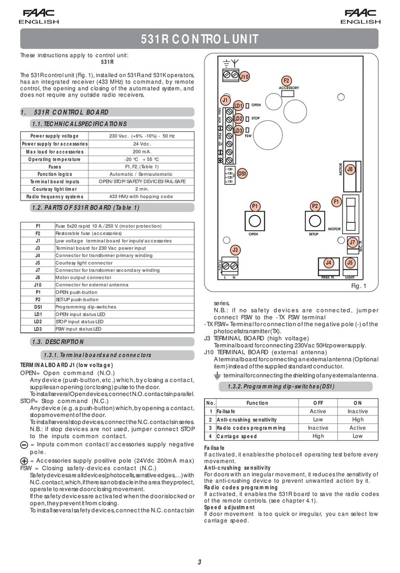
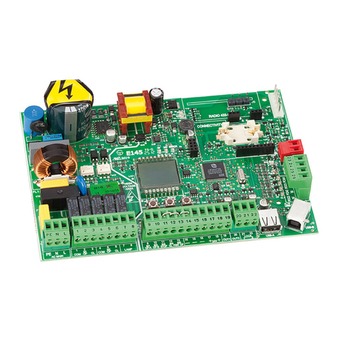
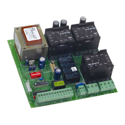
FAAC 275 H600 Technical document

Automatic concealed bollards
275 H600 and 275 H800
Control station
FAAC S.p.A. Via Benini, 1 40069 Zola Predosa Bologna (Italia) tel. +39 051 61724 www.faac.it

Technical installation manual
CE Declaration
Warnings for the installer
Bollard electrical connection
Technical specifications for control station
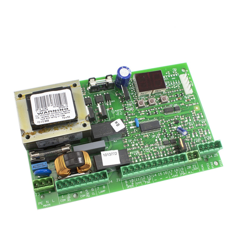
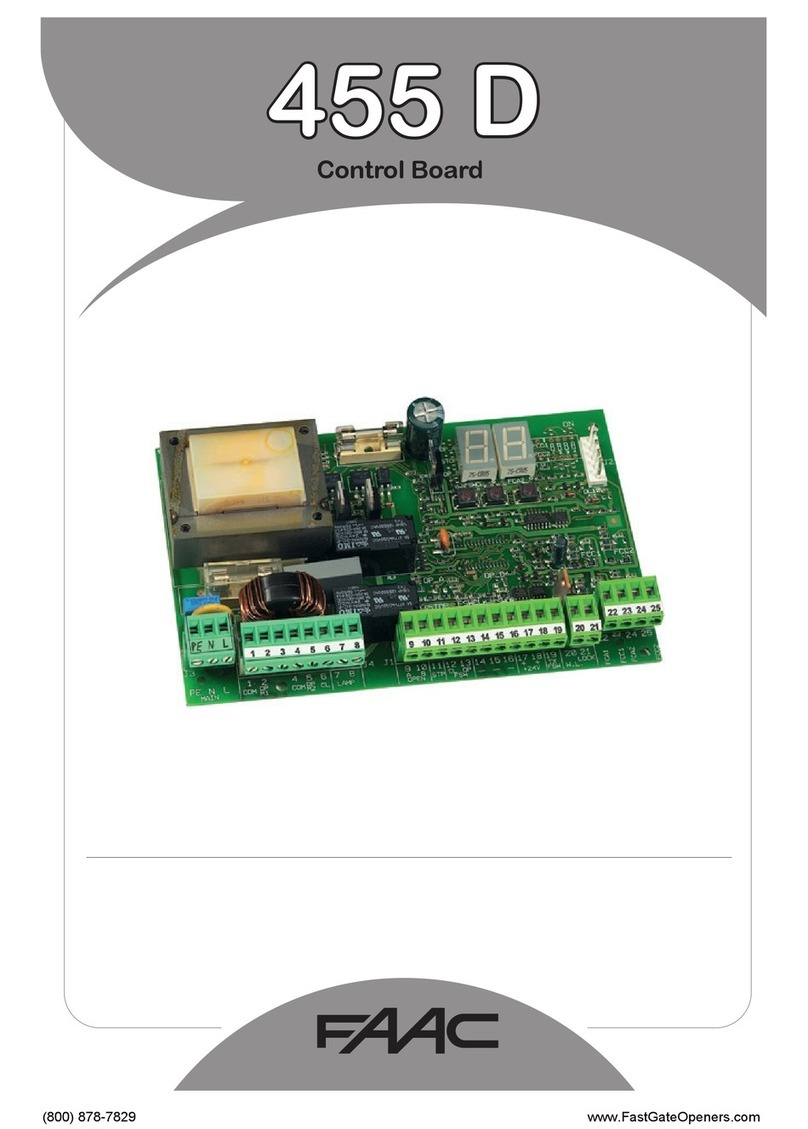
Control station lay-out
Dip-switches on control board
Connection terminal boards for control boards
FAAC S.p.A. Via Benini, 1 40069 Zola Predosa Bologna (Italia) tel. +39 051 61724 www.faac.it

CE DECLARATION OF CONFORMITY FOR MACHINES
(DIRECTIVE 98/37/CE)
Manufacturer: FAAC S.p.A.
Address: Via Benini, 1 - 40069 Zola Predosa BOLOGNA - ITALIA
Declares that: Faac City Master and Faac City Slave equipment
• conform to the essential safety requirements of the following EEC directives:
73/23/EEC and subsequent amendment 93/68/EEC.
89/336/EEC and subsequent amendment 92/31/EEC and 93/68/EEC
Additional information:
These products underwent tests in a typical, uniform configuration (all products manufactured
by FAAC S.p.A.).
Bologna, 01 January 2005
TheManagingDirector
A.Bassi
FAAC S.p.A. Via Benini, 1 40069 Zola Predosa Bologna (Italia) tel. +39 051 61724 www.faac.it

WARNINGS FOR THE INSTALLER - GENERAL SAFETY OBLIGATIONS
1 IMPORTANT! To ensure the safety of people, it is important
that all the instructions be carefully observed. Incorrect
installation or incorrect use of the product could cause
serious harm to people.
14 Make sure that the earthing system is workmanlike built and
connect the metal parts to it.
2 Carefully read the instructions before beginning to install
the product.
15 The automated system consists of an intrinsic anti-crushing
safety device controlling the torque. However, you must
check its action threshold as mentioned in the Regulations in
point 10.
3 Packing materials (plastic, polystyrene, etc.) must not be
left within the reach of children, because these materials
are potential danger sources.
16 Safety devices (EN 12978 standard) protect possible danger
areas against Mechanical movement risks. e.g. crushing,
carrying away and shearing.
4 Keep the instructions for future reference.
17 Use of at least one warning light is recommended for every
system (e.g. a built-in flashing light on the bollard head), a
warning sign, in addition to the devices mentioned in point
"16".
5 This product was designed and built exclusively for the use
indicated in this documentation. Any other use not
expressly indicated could compromise the integrity of the
product and/or be a source of danger.
18 For maintenance, strictly use original FAAC S.p.A. parts.
6 FAAC S.p.A. declines any responsibility due to improper
use or use other than the use for which the automated
system is intended.
19 FAAC S.p.A. declines all responsibility on the safety and
efficient operation of the automated system, if system
components not produced by FAAC S.p.A. are used.
7 Do not install the equipment in an explosive atmosphere.
the presence of gas or inflammable fumes is a serious
danger to safety.
20 Do not in any way modify the components of the FAAC CITY
automated system.
8 For non-EU countries, to achieve an adequate safety level,
the above mentioned standards must be observed in
addition to the national standard references.
21 The installer must supply to the user Customer, all the
information about the manual lowering of the bollard in case
of an emergency, and must hand over to the System User the
warning handbook which accompanies the product.
9 FAAC S.p.A. is not responsible for the non-observance of
good workmanship in installing FAAC CITY products and
the relevant accessories, or for any deformation which
may occur through use.
22 Do not allow children or persons to stay near the bollard,
especially while it is in operation.
10 The installation must be carried out by observing the
current regulations in force.
23 Keep radio controls or other pulse generators away from
children, to prevent the automated system from being
activated involuntarily.
11 Before attempting any action on the system, cut out the
electrical power supply.
24 The FAAC CITY bollard must be transited over only when the
device is completely lowered.
12 Install an all-pole switch on the electricity supply line for the
automated system, with contact opening distance of 3
mm or more. We advise you to use a 6A differential
thermal breaker with all-pole switching.
25 The User must not in any way attempt to repair or to take
direct action and must contact qualified authorised personnel
only.
13 Make sure that a differential switch with a threshold of
0.03A is installed upstream of the system.
26 Anything not expressly specified in these instructions is not
permitted.
FAAC S.p.A. Via Benini, 1 40069 Zola Predosa Bologna (Italia) tel. +39 051 61724 www.faac.it

TECHNICAL SPECIFICATIONS FOR CONTROL STATION
Electronic control circuit A microprocessor with specific software
for controlling FAAC CITY bollards
Enclosure for control station Wall fitting
Dimensions of enclosures According to system configuration
Protection class IP 55
Operating temperature -15°C + 70°C
Control station power supply 230V + 6/-10% 50Hz
Protective switch
(not supplied)
Differential thermal breaker
1P + N – 6 A ÷16 A - 30 mA – 6 KA
Service transformer 230/24Vac - 100 VA
Maximum number of FAAC CITIES
connectable to the control station
Max 10 FAAC CITIES with simultaneous
movement - the 1st FAAC CITY is
connected to the master unit -- the
others are connected to additional slave
units - the enclosure dimension depends
on the quantity of FAAC CITIES
WALL FITTING ENCLOSURES FOR STATIONS CONTROLLING THE MOVEMENT
OF FAAC CITY BOLLARDS
Dimensions
L x H x D
Material System configuration
300 X 380 X 160 GW PLAST 120° C - For basic system with 1 FAAC CITY
308 x 460 x 160 GW PLAST 120° C - For system with 1 accessory FAAC CITY
- For basic system with 2 FAAC CITIES
405 X 650 X 250 POLYESTER - For system with 3 accessory FAAC CITIES
- For basic system with 5 FAAC CITIES
515 X 650 X 250 POLYESTER - For system with 5 accessory FAAC CITIES
- For basic system with 8 FAAC CITIES
FAAC S.p.A. Via Benini, 1 40069 Zola Predosa Bologna (Italia) tel. +39 051 61724 www.faac.it

LAY-OUT OF FAAC CITY MASTER AND FAAC CITY SLAVE EQUIPMENT
Lay-outs of the Master and Slave equipment follow, with an indication of the function
of the signalling LEDs and of the protective fuses.
Master equipment - Lay-out and components
ELECTRONIC CIRCUIT
DIP-SWITCH FUNCTIONS
- Detector Input
- Start Input
- (Out) + 24V d.c. OK
- (Out) + 12V d.c. OK
- Out Green Traffic Lights
- Out Running
- Out Opened (down)
- Out Solenoid Valve
- Out Closed (up)
- Out Bollard (fix)
- Out Bollard (mobile)
- Out Acustic Bollard
- Pressure Sensor Input
L14
L11
L13
L12
L10
L9
L8
L7
L5
L6
L4
L3
L1
L2
PF6
- Aux Protection 24V
- Aux Protection
- Solenoid Valve Protection
- Traffic Lights Protection
- Clock Protection
- Transformer Protection
PF1
PF3
PF2
PF5
PF4
START
BUTTON
FAAC S.p.A. Via Benini, 1 40069 Zola Predosa Bologna (Italia) tel. +39 051 61724 www.faac.it

Slave equipment - Lay-out and components
- Transformer Protection
- AUX. Protection
- (Out) + 24V c.c. OK
- Limit SwitchOpening Input
- Pressure Sensor Input
PF1
PF2
L3
L2
L1
Slave/Slave
Connection
Master/Slave
Slave/Slave
Connection
FAAC S.p.A. Via Benini, 1 40069 Zola Predosa Bologna (Italia) tel. +39 051 61724 www.faac.it

POWER SUPPLY FOR FAAC CITY MASTER AND FAAC CITY SLAVE EQUIPMENT
The following are lay-outs of power supply connection to the Master board and to
the Master board with one or more Slaves connected in cascade mode.
The transformers are usually connected in the factory.
Note: FAAC Cities connected to the Slave boards perform the same movements of
the FAAC City connected to the Master board. If it is necessary to have different
movements performed by various bollards, a Master board for every type of
movement to be controlled must be installed.
230Vac Line
Optional Emergency Button
230 V
Optional Induttive Detector
Prearrangement N.C.
Prearrangement N.C.
Trasformer
100 VA
Faac City Connection
24 V 16 V 0 V
C6
Id 30mA
39
+24
LOOP
START
AUT
PR1
PR2
IN
24~+120V
ABC
12V 0 12V230V
12 3 54
1AT 2AT5AT2AT
38
37
36
34
33
32
31
35
30
29
28
27
25
24
23
22
21
26
20
230V
POWER 230V 230VSTOP
GRGR
NO NCCOM
1AT 2AT
230V
51
54
53
52
48
47
46
49
44
43
42
41
45
40
50
55 56
M
+
COM
BAC
+++
PR
13
14
15
16
17
19
18
7
10
11
12
8
9
4
2
5
6
1
3
2AT
595857
Master equipment - Power supply
FAAC S.p.A. Via Benini, 1 40069 Zola Predosa Bologna (Italia) tel. +39 051 61724 www.faac.it

100 VA
Transformer
Optional Emergency Button
Prearrangement N.C.
Optional Induttive Detector
Prearrangement N.C.
Master and Slave equipment - Power supply
230 V
Faac City 1 connection
BAC
COM
+
230V
START
AUT
LOOP
PR2
IN
PR1
12 3 54
12V +12 +24 24~012V ABC 0V
GRGR
230V
230V
230VSTOP
NO NCCOM
POWER
230V
2AT
5AT 1AT 2AT2AT2AT1AT
55
50
20
21
46
49
42
39
38
37
36
40
43
34
33
32
35
30
29
28
25
24
23
22
26
27
31
41
48
47
44
45
53
52
51
54
19
4
5
6
8
9
7
10
13
14
12
15
16
17
18
11
3
2
1
59
5756 58
MPR
+++
L3
012V
230V 12V
C
BA
2AT
5AT
L1
L2
+
+
COM
M
BCAPR
+
15
16
17
19
18
26
25
24
21
22
20
23
27
28
13
10
11
12
9
14
4
2
3
7
8
6
5
1
C10
Id 30mA
Faac City 2 connection
230Vac Line
FAAC S.p.A. Via Benini, 1 40069 Zola Predosa Bologna (Italia) tel. +39 051 61724 www.faac.it

100 VA
Trasformer
Optional Emergency Button
Prearrangement N.C.
Optional Induttive Detector
Prearrangement N.C.
Id 30mA
C10
24 V 0 V
230 V
16 V
Faac City 2 ConnectionFaac City 3 Connection Faac City 1 Connection
BAC
COM
+
230V
START
AUT
LOOP
PR2
IN
PR1
12 3 54
12V +12 +24 24~012V ABC 0V
GR G R
230V
230V
230VSTOP
NO NCCOM
POWER
230V
2AT
5AT 1AT 2AT2AT2AT1AT
55
50
20
21
46
49
42
39
38
37
36
40
43
34
33
32
35
30
29
28
25
24
23
22
26
27
31
41
48
47
44
45
53
52
51
54
19
4
5
6
8
9
7
10
13
14
12
15
16
17
18
11
3
2
1
595756 58
M
PR
+++
12V 12V0
230V
AC
B
2AT
5AT
L3
L3
L2
L1
012V
230V 12V
C
BA
2AT
5AT
L1
L2
+
M
COM
CBA
++
PR
+
+
COM
M
BCA
PR
+
15
22
20
21
19
18
28
23
24
25
26
27
6
13
14
17
16
15
9
12
11
10
8
7
5
3
2
4
1
16
17
19
18
26
25
24
21
22
20
23
27
28
13
10
11
12
9
14
4
2
3
7
8
6
5
1
Master and 2 Slave equipment - Power supply
230Vac Line
FAAC S.p.A. Via Benini, 1 40069 Zola Predosa Bologna (Italia) tel. +39 051 61724 www.faac.it

CONNECTION: BOLLARD TO CONTROL UNIT
The following lay-out shows the colours of the wires of the connection cable supplied
with the bollard, and how they are connected to the FAAC City Master equipment.
POWER CONNECTION - MODEL 275
11
12
14
16
15
13
7
4
6
8
4
Control board terminals
PR
CABLE 2x1
CABLE 2x1
CABLE 4G1
CABLE 5G0,5
2
4
3
1-6
5
6G0,7 SHIELDED CABLE
5G0,5 SHIELDED CABLE
4G1,5 SHIELDED CABLE
2
10
1
9
CABLE 2x1
FAAC S.p.A. Via Benini, 1 40069 Zola Predosa Bologna (Italia) tel. +39 051 61724 www.faac.it

FUNCTIONS OF DIP-SWITCHES OF FAAC CITY MASTER EQUIPMENT
Dip-switch No. 1 on the FAAC City Master board enables you to select the system's
function logic (automatic or semi-automatic).
Dip-switches 2, 3, 4, and 5 were fitted to facilitate diagnostic operations during
repair/maintenance of the systems.
In fact, if faults occur, instead of disconnecting the wires from the terminal boards,
you can exclude part of the circuits by suitably positioning the dip-switches.
DIP-SWITCH IN OFF POSITION DS No DIP-SWITCH IN ON POSITION
AUTOMATIC RISE ENABLED 1 AUTOMATIC RISE DISABLED
CONTROLS ENABLED 2 CONTROLS DISABLED
SAFETY DEVICES ENABLED 3 SAFETY DEVICES DISABLED
RISE TRAVEL-LIMIT PRESSURE SWITCH
ENABLED
4 RISE TRAVEL-LIMIT PRESSURE SWITCH
DISABLED
REVERSING PRESSURE SWITCH ENABLED 5 REVERSING PRESSURE SWITCH DISABLED
DIP – SWITCH 1
position to be defined depending on the system's use and configuration (if the safety
devices are not used, it must be positioned to ON):
OFF Position = AUTOMATIC RISE ENABLED: a bollard, which is normally in high
position, moves to low position following a command. When the vehicle has
transited through the controlled gate (and therefore trips and releases the safety
devices), the bollard returns to its high position. If the vehicle does not transit, the
bollard automatically returns to high position after 30". If the opening command is
maintained, the bollard stays in low position until release (timer function).
ON Position = AUTOMATIC RISE DISABLED: following a first command, the bollard
moves from high position to low position. Following another command, it returns
to high position .
FAAC S.p.A. Via Benini, 1 40069 Zola Predosa Bologna (Italia) tel. +39 051 61724 www.faac.it

DIP – SWITCH 2
Default position: OFF
OFF Position = CONTROLS ENABLED: the bollard movement controls connected to
terminals 24/25 – 26/27 – 58/59 are in operation.
ON Position = CONTROLS DISABLED: the bollard movement controls connected to
terminals 24/25 – 26/27 – 58/59 are disabled. If the FAAC CITY bollard does not rise,
you may temporarily disable the external control devices and use the push-button
on the board (START) to carry out the test.
DIP – SWITCH 3:
Default position: OFF
OFF Position = SAFETY DEVICES ENABLED: the inputs for the safety devices
(terminals 20/21) are enabled. If no safety devices are installed, jumper connect
terminals 20 and 21 to each other.
ON Position = SAFETY DEVICES DISABLED: the input for the safety devices (terminals
20/21) is disabled. If the FAAC CITY bollard does not rise, you may temporarily
disable the safety devices to check if they are to blame for the fault.
Note: for the installation of metal mass detection devices, consult the bollard
instructions and those for the individual devices.
DIP – SWITCH 4:
Default position: OFF
OFF Position = TRAVEL LIMIT RISE PRESSURE SWITCH ENABLED: during the final lifting
stage, the pressure switch symbol is used as a rise limit-switch.
ON Position = TRAVEL LIMIT RISE PRESSURE SWITCH DISABLED: the function described
above is disabled. The rise command is maintained during time out (it cannot be
modified)
FAAC S.p.A. Via Benini, 1 40069 Zola Predosa Bologna (Italia) tel. +39 051 61724 www.faac.it

DIP – SWITCH 5:
Default position OFF
OFF Position = REVERSING PRESSURE SWITCH ENABLED: during the lifting stage, if a
weight of over 50 Kg is detected, this trips the pressure switch, which is used as a
safety device to stop the bollard and return it to its low position.
ON Position = REVERSING PRESSURE SWITCH DISABLED: the function described
above is disabled. If the FAAC CITY bollard does not rise or, if during the rise stage,
the bollard re-descends for no apparent reason, you may temporarily exclude this
function to check if the pressure switch is to blame for the fault.
FAAC S.p.A. Via Benini, 1 40069 Zola Predosa Bologna (Italia) tel. +39 051 61724 www.faac.it

MASTER BOARD CONNECTION TERMINAL BOARD
Terminals 1-2-3= passing connection to 33-32-31 with protective fuse
Terminals 4-5-6-7-8 = connection for hydraulic power pack
Terminals 9-10 = Connection for automatic lowering device in the event of a 230V
power cut
Terminals 11-12 = connection to safety pressure switch
Terminal 13 = common contact for limit-switch - buzzer - flashing light
Terminal 14 = connection to FAAC CITY low limit-switch
Terminal 15 = connection for FAAC CITY intermittent buzzer
Terminal 16 = connection for flashing light incorporated into the head of FAAC CITY
Terminal 17 = common contact for limit-switch - buzzer - flashing light
Terminals 18-19 = connection for flashing lighted sign (24 Vac intermittent output)
Terminals 20-21-22-23 = connection for safety inductive detector
Terminals 24-25 = lowering command input
Terminals 26-27-28-29-30= connection for lowering command device
Terminals 31-32-33= passing connection to 3-2-1 with protective fuse
Terminals 34-35-36-37-38-39= connection for service transformer
Terminals 40-41-42 = 230V connection to 'traffic lights' 1
Terminals 43-44-45 = 230V connection to 'traffic lights' 2
Terminals 46-47-48= 'traffic lights' remote repetition (freed contact)
Terminals 49-50 = connection for emergency lowering push-button
Terminals 51-52= 230V connection to electronic circuit
Terminal 53 = not used
Terminal 54 = earth connection
Terminals 55-56-57-58-59 = connection for weekly/annual clock
FAAC S.p.A. Via Benini, 1 40069 Zola Predosa Bologna (Italia) tel. +39 051 61724 www.faac.it

SLAVE BOARD CONNECTION TERMINAL BOARD
Terminals 1-2-3= passing connection to 28-27-26 with protective fuse
Terminals 4-5-6-7-8 = connection for hydraulic power pack
Terminals 9-10 = connection for automatic lowering in the event of a 230V power cut
Terminals 11-12 = connection to safety pressure switch
Terminal 13 = common contact for limit-switch - buzzer - FAAC CITY flashing light
Terminal 14 = connection to FAAC CITY low limit-switch
Terminal 15 = connection for FAAC CITY intermittent buzzer
Terminal 16 = connection for flashing light incorporated into the head of FAAC CITY
Terminal 17 = common contact for limit-switch - buzzer - FAAC CITY flashing light
Terminals 18-19-20 = connection to service transformer
Terminal 21 = not used
Terminals 22-23= 230V connection to electronic circuit
Terminal 24 = not used
Terminal 25 = earth connection
Terminals 26-27-28= passing connection to 3-2-1 with (protective fuse)
FAAC S.p.A. Via Benini, 1 40069 Zola Predosa Bologna (Italia) tel. +39 051 61724 www.faac.it

FAAC S.p.A. Via Benini, 1 40069 Zola Predosa Bologna (Italia) tel. +39 051 61724 www.faac.it

FAAC S.p.A. Via Benini, 1 40069 Zola Predosa Bologna (Italia) tel. +39 051 61724 www.faac.it
FAAC S.p.A.
Via Benini, 1
40069 Zola Predosa (BO) - ITALIA
Tel.: 051/61724 - Fax: 051/758518
www.faac.it
Distributor’s Stamp:
The descriptions and illustrations contained in the present manual are not binding. FAAC reserves the right,
whilst leaving the main features of the equipments unaltered, to undertake any modifications it holds
necessary for either technical or commercial reasons, at any time and without revising the present
publication.
732868 rev. A
This manual suits for next models
1
Other FAAC Control Unit manuals
Popular Control Unit manuals by other brands

Keithley
Keithley 2657A-PM-200 user guide

Grundfos
Grundfos CIM 1 Series Installation and operating instructions

VAT
VAT 590 Series Installation, operating, & maintenance instructions

Parker
Parker Racor RK19506 instructions

Asco
Asco 8222 Series Installation & maintenance instructions

Panduit
Panduit IndustrialNet IAEBHUSBAA installation instructions

sensl
sensl HRM-TDC user manual

CTC Union
CTC Union ETU01 user manual

Pepperl+Fuchs
Pepperl+Fuchs VU121 Brief instructions

CALEFFI
CALEFFI LEGIOMIX 6000 series Installation and commissioning manual

Nordson
Nordson iTRAX PRx II Customer product manual

Caleffi solar
Caleffi solar 2522HP Series Installation, commissioning and servicing instructions