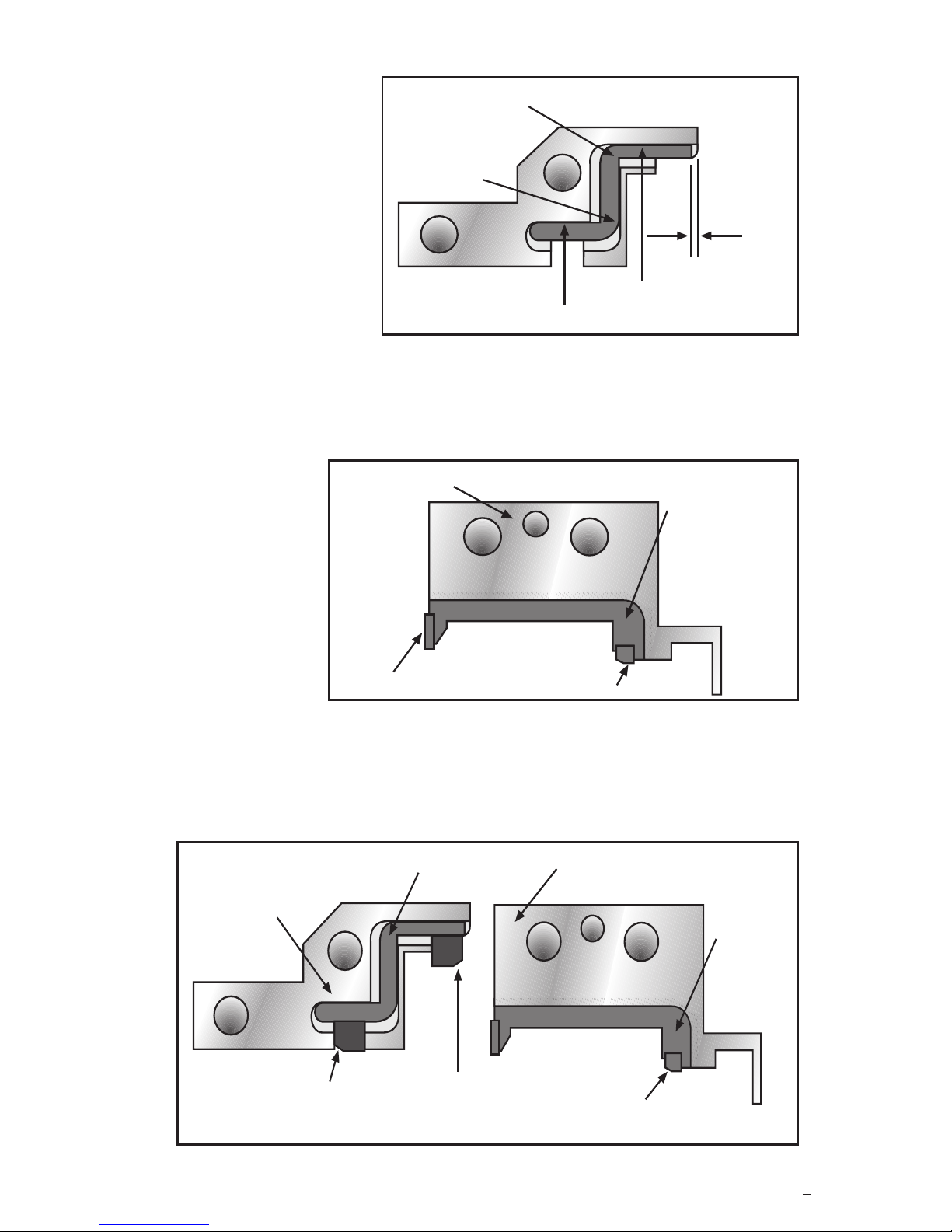
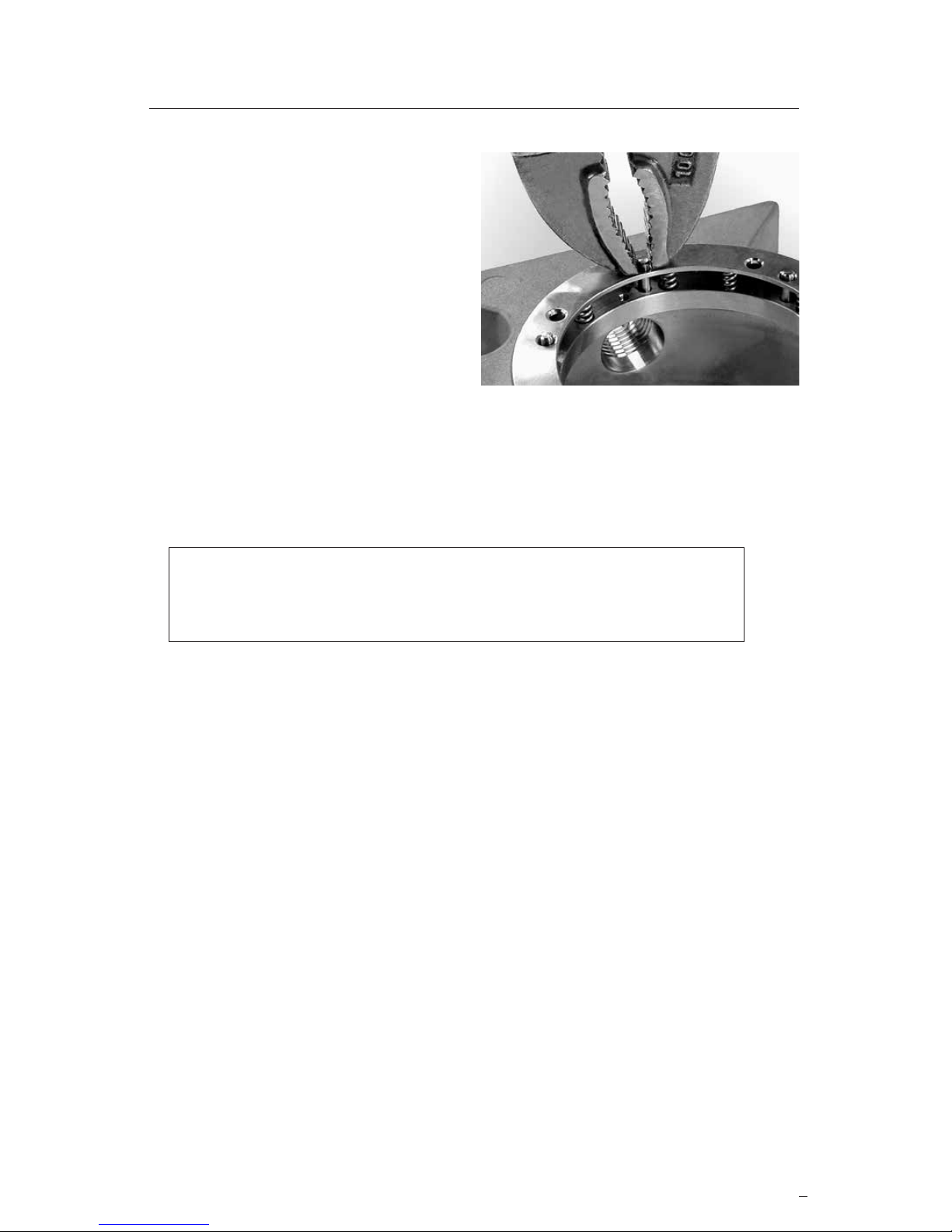
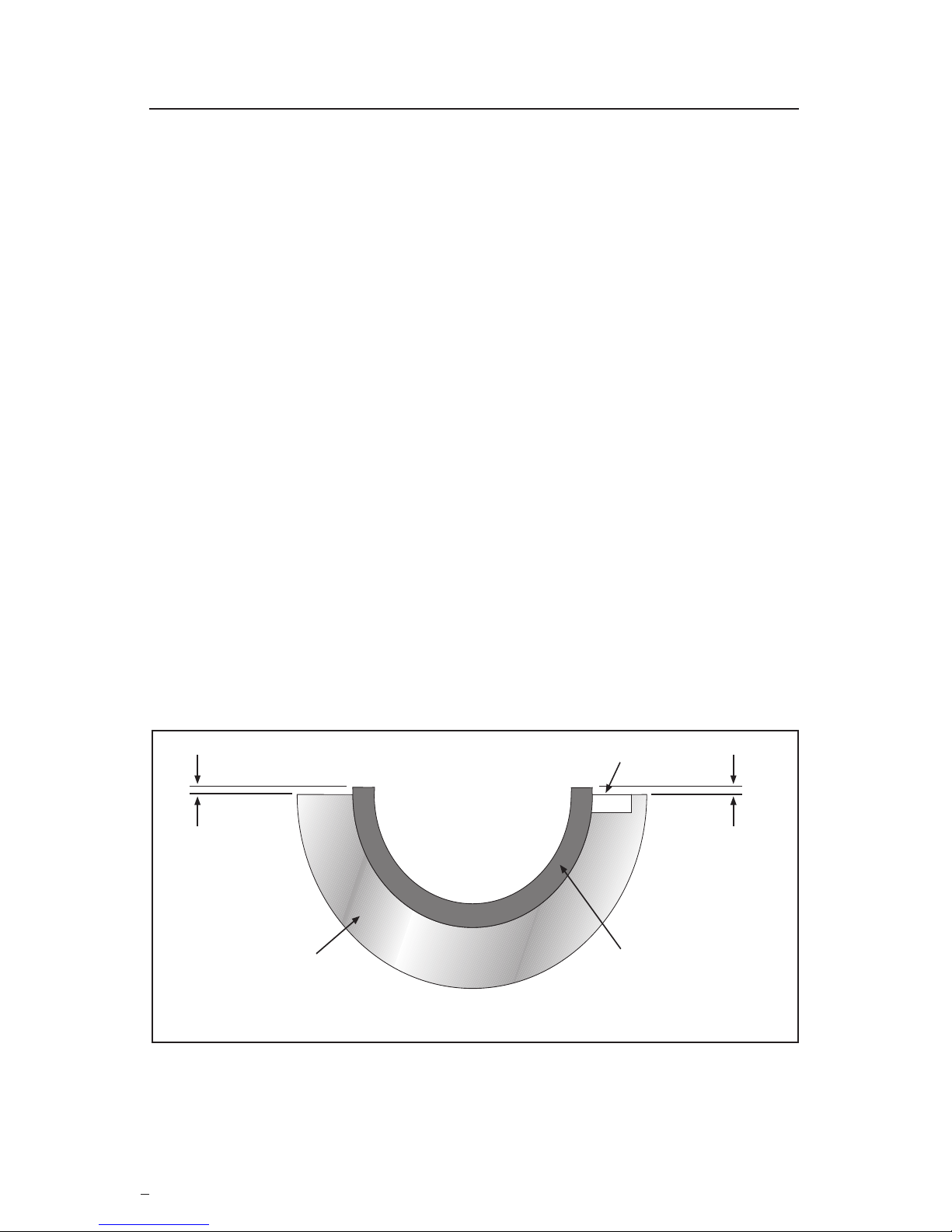
manuals.online logo
Brands
  1. Home
  2. •
  3. Brands
  4. •
  5. Flowserve
  6. •
  7. Industrial Equipment
  8. •
  9. Flowserve PSS II Setup guide

Flowserve PSS II Setup guide

Experience In Motion
Repair
Instructions
PSS II
Split Seal
2
These instructions are to be used in conjunction with the PSS II Repair
Kit. The Repair Kit contains replacement seal faces, secondary seals,
Loctite 430 adhesive, and Dow Corning 111 Silicone grease. Other
small parts are shown in Figure 1. The repair should be done in a clean,
well lit area. The tools you will need to do the repair include:
• Suitable solvent and rinse
• Alcohol
• Paper towels and/or swabs
• Single edged razor blade or Exacto style knife
• Common screw driver
• Hex key wrenches
• Paper clip
• Anti-seize thread compound
These instructions require the gluing of elastomers into position with
Loctite 430. As with any cyanoacrylate, extreme care must be used when
handling Loctite 430. See the enclosed Material Safety Data Sheet for
details.
For special problems encountered during the repair procedure,
contact your nearest Flowserve Sales and Service Representative or
Authorized Distributer.
Figure 1
1 Registered Trademark of Loctite Corporation
2 Registered Trademark of Dow Corning Corporation
® 1 ® 2
TM
3
1 Disassemble and Clean
1.1 Remove the cap screws from
the seal drive and gland.
1.2 Remove the rotating and
stationary face halves by
lifting the center of each face
up above their drive or lock
pins and sliding the face
away from the seal drive or
gland.
1.3 Remove the spring
holder by pulling out
the lock pins. See Figure 2.
1.4 Soak the parts in a solvent to remove the secondary seals, adhe-
sive, grease, etc. Suggested solvents include:
•Loctite X-NMS 768
•Acetone
•Trichloroethane (chlorothene)
Note: Follow all Material Safety Data Sheet (MSDS) recommendations
when handling these uids.
1.5 Remove any remaining adhesive by brushing or lightly scraping.
1.6 Wash parts in hot soapy water. Rinse thoroughly in clean water.
Let parts dry.
Caution: Do not sand or bead blast gasket and joint surfaces in the
seal drive and gland to avoid damaging them. Glue, rubber, or heavy
deposits must be carefully scraped off these surfaces before gasketing.
Figure 2
© Copyright 2015 Flowserve Corporation
4
During the assembly process follow these inspection procedures to avoid
errors which may not be correctable later.
2.1 Check Adhesion - Gently tug at the gaskets to be sure they are
properly secured. If they come loose easily, it is likely that the
surfaces were not adequately cleaned or rinsed. Clean the surface
again and reapply adhesive per the instructions. Apply small dots
of adhesive only where specied. Dot size should be 0.040 to
0.080 inch (1.00 to 2.00 mm) in diameter.
2.2 Gasket Length - Be sure that the rotating face gasket, stationary
face seat gasket, and seal drive sleeve gasket are 0.025 to
0.035 inch (0.65 to 0.90 mm) longer than the surfaces where they
end. See Figure 3. If they are not, reposition them accordingly.
Note: All circumferential gaskets are cut to the proper length at the
factory and require no further trimming. The circumferential gaskets will
appear to be too long for the groove. The extra length of the gasket will
be compressed into the groove between the glued points at each joint
during seal assembly.
0.025 - 0.035"
(0.65 to 0.90 mm)
Seal Drive
or Gland
Rotating Face Gasket,
Seat Gasket, or
Sleeve Gasket
Figure 3
0.025 - 0.035"
(0.65 - 0.90 mm)
Split Joint Gasket Groove
2 Ongoing Inspection
2.4 Gland Split
Joint
Gasket
Position
The gland
split joint
gaskets
must be
positioned
as shown in
Figure 5. If
they are not,
Split Joint
Gasket
Gland
Seat Gasket
Gland Gasket
Figure 5
5
2.5 Gasket Chamfers - The seat gasket, rotating face gasket, and
sleeve gasket are all chamfered on one side and must be
positioned as shown in Figure 6.
Figure 6
Rotating Face
Gasket
Chamfer Side
Seal Drive
Sleeve Gasket
Chamfer Side
Gland
Split Joint Gasket
Split
Joint
Gasket
Seat Gasket
Chamfer Side
2.3 Seal Drive Split
Joint Gasket
Position
The split joint
gaskets should be
positioned ush
with the groove
surfaces indicated
in Figure 4. The
gasket end should
be ush to 0.030
inch (0.76 mm)
shorter than the
groove as shown.
Flush
Flush
Flush
Split Joint Gasket
Figure 4
0.030"
0.000"
(0.76 -
0.00 mm)
reposition them as needed.
Figure 10
Figure 7
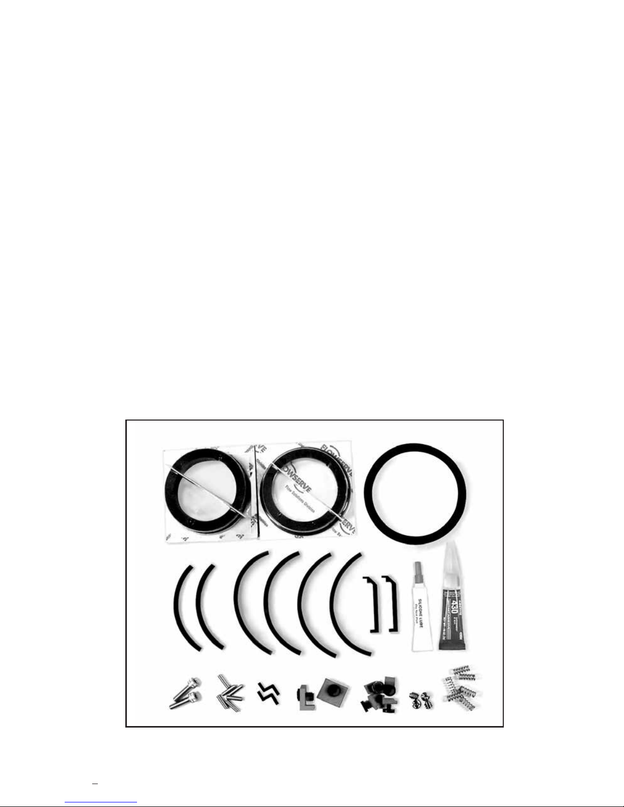
3 Sleeve Gasket and Rotating Face Gasket
Installation
Figure 8
Figure 9
6
3.1 Wipe the sleeve gasket groove
clean with alcohol.
Caution: Consult material safety data sheets
for proper handling of alcohol.
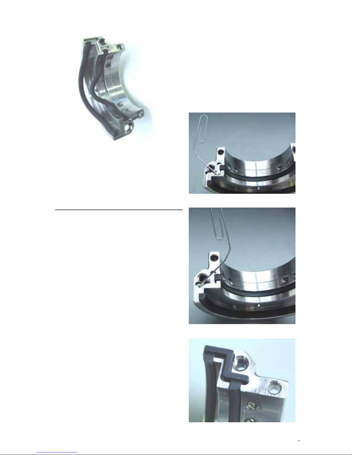
3.2 Install the sleeve gasket into the
groove. Hold the gasket in the
groove and adjust it so the end
extends 0.025 to 0.035 inch
(0.65 to 0.90 mm) past the seal
drive joint surface. See Figure 7.
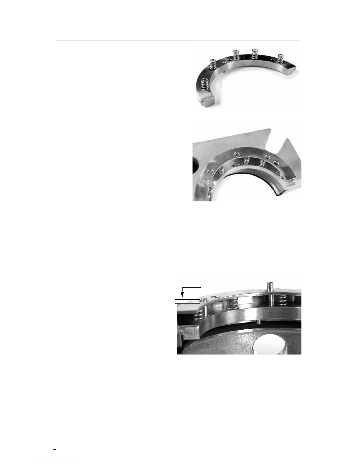
3.3 Check the gasket extension with
the 0.030 inch (0.76 mm) thick
"Proud" gauge. See Figure 8.
Note: All circumferential gaskets are
cut to the proper length at the factory
and require no further trimming. The
circumferential gaskets will appear to
be too long for the groove. The extra
length of the gasket is compressed
into the groove between the
glue points.
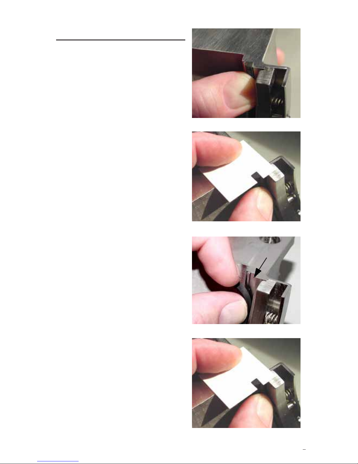
3.4 Pull back 0.50 inch (12.7 mm) of
the sleeve gasket and use a
paper clip to put two dots of
adhesive in the groove
approximately 0.25 inch (6.35
mm) and 0.50 inch (12.7 mm)
from the seal drive joint surface.
See Figure 9.
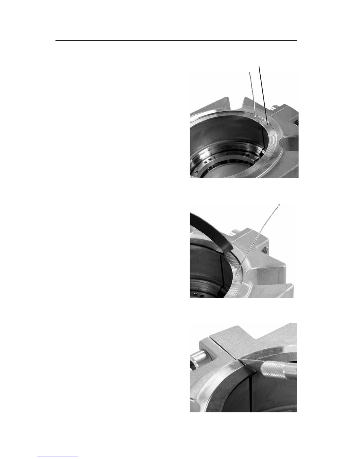
3.5 Push the end into the adhesive
and check the gasket extension
with the "Proud" gauge. Hold it
in place for 10 seconds.
See Figure 10.
3.6 Glue the other end of the sleeve
gasket in the groove using the
same procedure.
7
Figure 11
3.7 Repeat these steps for
the rotating face gasket.
3.8 Push the draped middle of
the sleeve gasket and
rotating face gasket into
their grooves. Do not
apply adhesive.
See Figure 11.
Figure 12
Figure 13
Figure 14
3.9 Repeat this procedure for the
other seal drive half.
4 Seal Drive Split Joint
Gasket Installation
4.1 Wipe the seal drive's split joint
gasket groove clean with
alcohol.
Caution: Consult material safety data sheets
for proper handling of alcohol.
4.2 Put one dot of adhesive near the
inner corner. See Figure 12.
4.3 Put one dot of adhesive near the
outer corner. See Figure 13.
4.4 Place the split joint gasket in the
groove and position it as shown
in Figure 4. Hold it in place for
10 seconds. See Figure 14.
4.5 Repeat this procedure for the
other seal drive half.
Figure 15
Figure 16
8
5.1 Place the coil springs in the
spring holes. See Figure 15.
5.2 Set the gland half face down
on the table and insert half of
the spring holder into the gland.
See Figure 16.
5.3 Lubricate one end of the lock
pins and set them into the lock
pin holes in the gland and align
them with the holes in the spring
holder.
5 Spring Holder Installation
Figure 17
5.4 Keep the spring holder snug in
the gland bore and press the
lock pins into the spring holder
until the pins extend 0.06 inch
(1.5 mm) out of the gland. See
Figure 17.
5.5 Repeat this procedure for the other gland half.
0.06" (1.5 mm)
9
Figure 20
Figure 19
Figure 18
6 Seat Gasket Installation
6.1 Wipe the gland seat gasket
groove clean with alcohol.
Caution: Consult material safety data
sheets for proper handling of alcohol.
6.2 Install the seat gasket into the
groove. Hold the seat gasket
in the groove and adjust it so
the end extends 0.025 to 0.035
inch (0.65 to 0.90 mm) past the
gland joint surface.
See Figure 18.
6.3 Check the gasket extension with
the 0.030 inch (0.76 mm)
"Proud" gauge. See Figure 19.
6.4 Pull back 0.50 inch (12.7 mm) of
the seat gasket. Use a paper
clip to put two dots of adhesive
in the groove approximately
0.25 inch (6.35 mm) and 0.50
inch (12.7 mm) from the gland
joint surface. See Figure 20.
6.5 Push the end into the adhesive
and check the gasket extension
with the "Proud" gauge. Hold it
in place for 10 seconds.
See Figure 21.
6.6 Glue the other seat gasket end
into the groove using the same
steps.
6.7 Push the middle of the gasket
into the groove. Do not apply
adhesive.
6.8 Repeat this procedure for the
other gland half. Figure 21
Figure 24
10
Figure 22
7 Gland Gasket Installation
7.1 The gland gasket should be
installed with one dot of
adhesive every 0.50 inch
(12.7 mm) with an extra dot of
adhesive 0.25 inch (6.35 mm)
both sides of the gland joint.
7.2 Coat the cap screws with anti-
seize and assemble the gland
halves. Tighten the cap screws
until the gland joints are metal to
metal.
7.3 Wipe the gland gasket groove
clean with alcohol.
Caution: Consult material safety data
sheets for proper handling of alcohol.
7.4 Apply one dot of adhesive to the
gland gasket groove about 0.25
inch (6.35 mm) from a gland
joint. See Figure 22.
7.5 Center the gland gasket in the
gasket groove and hold it in
place for 10 seconds.
7.6 Apply another dot of adhesive
0.50 inch (12.7 mm from
the rst dot and hold the gland
gasket at that dot for
10 seconds.Repeat this step
every 0.50 inch (12.7mm)
around the groove
circumference. See Figure 23.
7.7 Loosen the cap screws about
1/2 turn. Spread the gland joints
and cut the gland gasket at
these locations. See Figure 24.
Face Gasket Groove
Figure 23
11
Figure 25
Figure 26
8 Gland Split Joint Gasket Installation
Figure 27
2 Dots Here
8.1 Wipe the gland split joint gasket
groove clean with alcohol.
Caution: Consult material safety data sheets
for proper handling of alcohol.
8.2 Put one dot of adhesive in the
groove as shown in Figure 25.
One Dot Here
8.3 Place the split joint gasket in the groove. Make sure it is ush with
the back of the gland gasket, the back and top of the seat gasket,
and the top of the split joint gasket groove. Hold it in place for
10 seconds. See Figure 26.
8.4 Apply two more dots of glue as
shown in Figure 27.
8.5 Align the split joint gasket with
the seat gasket and gland
gasket as shown in Figure 26.
Hold it in place for 10 seconds.
8.6 Repeat this procedure for the
other gland half.
Flush
Flush
Flush
12
Figure 28
9 Rotating Face Installation
9.1 Lubricate the exposed surfaces
of the rotating face gasket
including the ends and the
rotating face shoulder with
silicone grease.
9.2 With the seal drive sitting on the
bench, set the rotating face on
it. See Figure 28.
Figure 29
9.3 Align the drive pin and drive slot.
9.4 Push the rotating face radially into the seal drive and then down as
the drive pin slips into the drive slot.
9.5 Repeat this procedure to install the other rotating face half.
9.6 Lubricate the exposed surfaces of each sleeve gasket including
the ends and the split joint gaskets with silicone grease.
9.7 Loosely cap screw the havles together.
9.8 Align the rotating faces and wipe clean with alcohol.
Caution: Consult material safety data sheets for proper handling of alcohol.
10 Stationary Face Installation
10.1 Lubricate the exposed surfaces of the seat gasket including the
ends and the stationary face shoulder with silicon grease.
10.2 With the gland sitting on the bench, set the stationary face on the
spring holder as shown in Figure 29.
10.3 Align the lock pin and lock pin slot.
13
10.4 Push the stationary face radially into the gland and then down as
the lock pin slips into the lock pin slot. The stationary face should
sit ush with the spring holder.
10.5 Repeat this procedure for the other gland half.
10.6 Lubricate the exposed surfaces of the split joint gaskets with silicon
grease.
10.7 Loosely cap screw the halves together.
10.8 Align the stationary faces and wipe them clean with alcohol.
Caution: Consult material safety data sheets for proper handling of alcohol.
11 Centering Device Installation
11.1 Place the gland assembly on
the table face down.
11.2 Set one centering device on
the gland and press the
centering device fastener
through the centering device
and into the locating hole in
the gland. The locating holes
are located 45 degrees from
the split joints and are even
with the bolt slots.
See Figure 30.
Note: Newer PSS II seal designs
use a one piece centering device
that can be pressed into place
without a separate fastener.
11.3 Repeat this procedure for all
four centering devices.
See Figure 31.
Figure 31
Figure 30
14
Figure 32
12 Setting Device Installation
12.1 Push the plastic fastener through the hole in a setting device as
shown in Figure 32.
12.2 Push the fastener into the side hole of the seal drive.
See Figure 32.
12.3 Repeat this procedure for the other setting device.
15
For proper seal installation, please refer to Flowserve publication FIS145,
PSS II Installation Instructions.
13 Seal Reference
Seal
Drive
Shaft and
Seal Size
Stationary
Face
Centering
Device
Set
Screw
Rotating
Face
.19" (4.8 mm) maximum
.10" (2.5 mm) minimum
Pin Extension
1 - NPT
For Flushing
45°
TO REORDER REFER TO
B/M #
F.O.
flowserve.com
To find your local Flowserve representative
and find out more about Flowserve Corporation,
visit www.flowserve.com
FIS147eng REV 09/2018 Printed in USA
Flowserve Corporation has established industry leadership in the design and manufacture of its products.
When properly selected, this Flowserve product is designed to perform its intended function safely during
its useful life. However, the purchaser or user of Flowserve products should be aware that Flowserve
products might be used in numerous applications under a wide variety of industrial service conditions.
Although Flowserve can provide general guidelines, it cannot provide specific data and warnings for all
possible applications. The purchaser/user must therefore assume the ultimate responsibility for the proper
sizing and selection, installation, operation, and maintenance of Flowserve products. The purchaser/user
should read and understand the Installation Instructions included with the product, and train its employees
and contractors in the safe use of Flowserve products in connection with the specific application.
While the information and specifications contained in this literature are believed to be accurate, they
are supplied for informative purposes only and should not be considered certified or as a guarantee of
satisfactory results by reliance thereon. Nothing contained herein is to be construed as a warranty or
guarantee, express or implied, regarding any matter with respect to this product. Because Flowserve is
continually improving and upgrading its product design, the specifications, dimensions and information
contained herein are subject to change without notice. Should any question arise concerning these
provisions, the purchaser/user should contact Flowserve Corporation at any one of its worldwide
operations or offices.
USA and Canada
Kalamazoo, Michigan USA
Telephone: 1 269 381 2650
Telefax: 1 269 382 8726
Europe, Middle East, Africa
Etten-Leur, the Netherlands
Telephone: 31 765 028 200
Telefax: 31 765 028 487
Asia Pacific
Singapore
Telephone: 65 6544 6800
Telefax: 65 6214 0541
Latin America
Mexico City
Telephone: 52 55 5567 7170
Telefax: 52 55 5567 4224

Other Flowserve Industrial Equipment manuals

Flowserve ISC1PX Setup guide

Flowserve

Flowserve ISC1PX Setup guide

Flowserve Limitorque HBC Series User manual

Flowserve

Flowserve Limitorque HBC Series User manual

Flowserve Limitorque Accutronix MX Guide

Flowserve

Flowserve Limitorque Accutronix MX Guide

Flowserve Durametallic MD-200 Series User manual

Flowserve

Flowserve Durametallic MD-200 Series User manual

Flowserve 682-53B System User manual

Flowserve

Flowserve 682-53B System User manual

Flowserve 682R User manual

Flowserve

Flowserve 682R User manual

Flowserve 400-D Installation instructions

Flowserve

Flowserve 400-D Installation instructions

Popular Industrial Equipment manuals by other brands

LDC EQUIPMENT LDC ABC Installation and instruction manual

LDC EQUIPMENT

LDC EQUIPMENT LDC ABC Installation and instruction manual

Phoenix Contact IL PB BK DI8 DO4/EF-PAC user manual

Phoenix Contact

Phoenix Contact IL PB BK DI8 DO4/EF-PAC user manual

Grundfos Polydos 412E instructions

Grundfos

Grundfos Polydos 412E instructions

ITW Simco-Ion Pinner Series Installation and operating instruction

ITW

ITW Simco-Ion Pinner Series Installation and operating instruction

SAMCHULLY MUT-600 instruction manual

SAMCHULLY

SAMCHULLY MUT-600 instruction manual

ABB HT847308 Operation manual

ABB

ABB HT847308 Operation manual

Afag HLF07-P Operating & installation instructions

Afag

Afag HLF07-P Operating & installation instructions

THORLABS M F1 Series Operation manual

THORLABS

THORLABS M F1 Series Operation manual

flamco FlexFiller Direct G4 Installation and operating manual

flamco

flamco FlexFiller Direct G4 Installation and operating manual

KTC GZR18 instruction manual

KTC

KTC GZR18 instruction manual

National Instruments NI 9476 Getting started

National Instruments

National Instruments NI 9476 Getting started

SPX MARLEY Geareducer 2700 Series user manual

SPX

SPX MARLEY Geareducer 2700 Series user manual

Siemens SIMATIC NET installation manual

Siemens

Siemens SIMATIC NET installation manual

Axminster AW150SM Original instructions

Axminster

Axminster AW150SM Original instructions

Lauda UWT Series operating instructions

Lauda

Lauda UWT Series operating instructions

Siemens MMB300 operating instructions

Siemens

Siemens MMB300 operating instructions

Ranger RP-20FC Installation and operation manual

Ranger

Ranger RP-20FC Installation and operation manual

TÜNKERS ALPHA APH... FUZ B Series operating instructions

TÜNKERS

TÜNKERS ALPHA APH... FUZ B Series operating instructions

manuals.online logo
manuals.online logoBrands
  • About & Mission
  • Contact us
  • Privacy Policy
  • Terms and Conditions

Copyright 2025 Manuals.Online. All Rights Reserved.