Fluke Biomedical ProSim 2 User manual

Artisan Technology Group is your source for quality
new and certied-used/pre-owned equipment
• FAST SHIPPING AND
DELIVERY
• TENS OF THOUSANDS OF
IN-STOCK ITEMS
• EQUIPMENT DEMOS
• HUNDREDS OF
MANUFACTURERS
SUPPORTED
• LEASING/MONTHLY
RENTALS
• ITAR CERTIFIED
SECURE ASSET SOLUTIONS
SERVICE CENTER REPAIRS
Experienced engineers and technicians on staff
at our full-service, in-house repair center
WE BUY USED EQUIPMENT
Sell your excess, underutilized, and idle used equipment
We also offer credit for buy-backs and trade-ins
www.artisantg.com/WeBuyEquipment
REMOTE INSPECTION
Remotely inspect equipment before purchasing with
our interactive website at www.instraview.com
LOOKING FOR MORE INFORMATION?
Visit us on the web at www.artisantg.com for more
information on price quotations, drivers, technical
specications, manuals, and documentation
Contact us: (888) 88-SOURCE | sales@artisantg.com | www.artisantg.com
SM
View
Instra

FBC 0038
January 2013, Rev. 1
© 2013 Fluke Corporation. All rights reserved. Specifications are subject to change without notice.
All product names are trademarks of their respective companies.
ProSim™ 2/3
Vital Signs Simulator
Users Manual

Warranty and Product Support
Fluke Biomedical warrants this instrument against defects in materials and workmanship for one year from the date of original
purchase OR two years if at the end of your first year you send the instrument to a Fluke Biomedical service center for
calibration. You will be charged our customary fee for such calibration. During the warranty period, we will repair or at our
option replace, at no charge, a product that proves to be defective, provided you return the product, shipping prepaid, to Fluke
Biomedical. This warranty covers the original purchaser only and is not transferable. The warranty does not apply if the
product has been damaged by accident or misuse or has been serviced or modified by anyone other than an authorized Fluke
Biomedical service facility. NO OTHER WARRANTIES, SUCH AS FITNESS FOR A PARTICULAR PURPOSE, ARE
EXPRESSED OR IMPLIED. FLUKE SHALL NOT BE LIABLE FOR ANY SPECIAL, INDIRECT, INCIDENTAL OR
CONSEQUENTIAL DAMAGES OR LOSSES, INCLUDING LOSS OF DATA, ARISING FROM ANY CAUSE OR THEORY.
This warranty covers only serialized products and their accessory items that bear a distinct serial number tag. Recalibration of
instruments is not covered under the warranty.
This warranty gives you specific legal rights and you may also have other rights that vary in different jurisdictions. Since some
jurisdictions do not allow the exclusion or limitation of an implied warranty or of incidental or consequential damages, this
limitation of liability may not apply to you. If any provision of this warranty is held invalid or unenforceable by a court or other
decision-maker of competent jurisdiction, such holding will not affect the validity or enforceability of any other provision.
7/07

Notices
All Rights Reserved
Copyright 2012, Fluke Biomedical. No part of this publication may be reproduced, transmitted, transcribed, stored in a retrieval system, or translated into any
language without the written permission of Fluke Biomedical.
Copyright Release
Fluke Biomedical agrees to a limited copyright release that allows you to reproduce manuals and other printed materials for use in service training programs and
other technical publications. If you would like other reproductions or distributions, submit a written request to Fluke Biomedical.
Unpacking and Inspection
Follow standard receiving practices upon receipt of the instrument. Check the shipping carton for damage. If damage is found, stop unpacking the instrument.
Notify the carrier and ask for an agent to be present while the instrument is unpacked. There are no special unpacking instructions, but be careful not to damage
the instrument when unpacking it. Inspect the instrument for physical damage such as bent or broken parts, dents, or scratches.
Technical Support
For application support or answers to technical questions, either email [email protected] or call 1-800- 850-4608 or 1-440-248-9300. In
Claims
Our routine method of shipment is via common carrier, FOB origin. Upon delivery, if physical damage is found, retain all packing materials in their original
condition and contact the carrier immediately to file a claim. If the instrument is delivered in good physical condition but does not operate within specifications, or
if there are any other problems not caused by shipping damage, please contact Fluke Biomedical or your local sales representative.
Returns and Repairs
Return Procedure
All items being returned (including all warranty-claim shipments) must be sent freight-prepaid to our factory location. When you return an instrument to Fluke
Biomedical, we recommend using United Parcel Service, Federal Express, or Air Parcel Post. We also recommend that you insure your shipment for its actual
replacement cost. Fluke Biomedical will not be responsible for lost shipments or instruments that are received in damaged condition due to improper packaging
or handling.
Use the original carton and packaging material for shipment. If they are not available, we recommend the following guide for repackaging:
Use a double–walled carton of sufficient strength for the weight being shipped.
Use heavy paper or cardboard to protect all instrument surfaces. Use nonabrasive material around all projecting parts.
Use at least four inches of tightly packed, industry-approved, shock-absorbent material around the instrument.

Returns for partial refund/credit:
Every product returned for refund/credit must be accompanied by a Return Material Authorization (RMA) number, obtained from our Order Entry Group at 1-
440-498-2560.
Repair and calibration:
To find the nearest service center, go to www.flukebiomedical.com/service or
In the U.S.A.:
Cleveland Calibration Lab
Tel: 1-800-850-4608 x2564
Everett Calibration Lab
Tel: 1-888-99 FLUKE (1-888-993-5853)
In Europe, Middle East, and Africa:
Eindhoven Calibration Lab
Tel: +31-40-2675300
In Asia:
Everett Calibration Lab
Tel: +425-446-6945
To ensure the accuracy of the Product is maintained at a high level, Fluke Biomedical recommends the product be calibrated at least once every
12 months. Calibration must be done by qualified personnel. Contact your local Fluke Biomedical representative for calibration.
Certification
This instrument was thoroughly tested and inspected. It was found to meet Fluke Biomedical’s manufacturing specifications when it was shipped from the
factory. Calibration measurements are traceable to the National Institute of Standards and Technology (NIST). Devices for which there are no NIST calibration
standards are measured against in-house performance standards using accepted test procedures.
WARNING
Unauthorized user modifications or application beyond the published specifications may result in electrical shock hazards or improper operation. Fluke
Biomedical will not be responsible for any injuries sustained due to unauthorized equipment modifications.

Restrictions and Liabilities
Information in this document is subject to change and does not represent a commitment by Fluke Biomedical. Changes made to the information in
this document will be incorporated in new editions of the publication. No responsibility is assumed by Fluke Biomedical for the use or reliability of
software or equipment that is not supplied by Fluke Biomedical, or by its affiliated dealers.
Manufacturing Location
The ProSim™ 2/3 Vital Signs Simulator is manufactured at Fluke Biomedical, 6920 Seaway Blvd., Everett, WA, U.S.A.


i
Table of Contents
Title Page
Introduction.................................................................................................................... 1
Safety Information.......................................................................................................... 1
Accessories ................................................................................................................... 4
Product Familiarization .................................................................................................. 5
Battery Eliminator .......................................................................................................... 8
How to Turn On the Product .......................................................................................... 8
Operation....................................................................................................................... 9
Cardiac Functions.......................................................................................................... 10
ECG Functions.......................................................................................................... 10
Pacemaker Signals ................................................................................................... 13
Arrhythmia Function.................................................................................................. 13
ECG Tests ................................................................................................................ 14
How to Set a Performance Wave Output ............................................................. 14
R-Wave Detection Test ........................................................................................ 14
Blood Pressure Function........................................................................................... 15
How to Set the BP Sensitivity............................................................................... 15
How to Set Up a BP Channel ............................................................................... 15
Dynamic BP Waveforms ...................................................................................... 15
How to Add a Respiration Artifact to the BP Waveform ....................................... 17
Cardiac Output.......................................................................................................... 17

ProSim™ 2/3
Users Manual
ii
Cardiac-Output Test Set Up ................................................................................. 17
How to Simulate Injectate Failure and Left-to-Right Shunt Fault.......................... 19
How to Simulate Output from a Calibrated Pulse Signal ...................................... 19
Fetal/Maternal Function ............................................................................................ 21
Simulate Fixed Fetal Heart Rate (FHR)................................................................ 21
How to Simulate a Periodic FHR with Intrauterine Pressure (IUP) ....................... 21
Other Functions ............................................................................................................. 24
Respiration Functions ............................................................................................... 24
Temperature ............................................................................................................. 24
Remote Operation ......................................................................................................... 26
Remote Commands .................................................................................................. 27
General Commands .................................................................................................. 28
Function Commands ................................................................................................. 28
ECG Functions..................................................................................................... 28
Arrhythmia Functions ........................................................................................... 31
ECG Test Functions ............................................................................................. 32
Respiration Function Commands ......................................................................... 35
Blood Pressure Function Commands................................................................... 36
Other Function Commands .................................................................................. 40
Maintenance .................................................................................................................. 41
General Maintenance................................................................................................ 41
Battery Replacement................................................................................................. 42
General Specifications ................................................................................................... 43
Detailed Specifications................................................................................................... 43
ECG Waveform......................................................................................................... 43
Pacemaker Waveform............................................................................................... 44
Arrhythmia................................................................................................................. 44
ECG-Performance-Tests........................................................................................... 45
Respiration................................................................................................................ 45
Blood Pressure ......................................................................................................... 45
Temperature ............................................................................................................. 47
Cardiac Output (ProSim 3 Only) ............................................................................... 47
Fetal / Maternal-ECG (ProSim 3 Only)...................................................................... 47
Computer Setup........................................................................................................ 48

iii
List of Tables
Table Title Page
1. Symbols ................................................................................................................................ 3
2. Standard Accessories ........................................................................................................... 4
3. Optional Accessories ............................................................................................................ 4
4. Front-Panel Controls and Connectors .................................................................................. 6
5. Top-Panel Connectors .......................................................................................................... 7
6. Product Functions................................................................................................................. 9
7. Dynamic BP Waveforms by BP Channel .............................................................................. 16
8. Error Codes .......................................................................................................................... 27
9. Product Control States and Modes ....................................................................................... 28
10. General Commands.............................................................................................................. 28
11. ECG Function Commands .................................................................................................... 28
12. Pacemaker Waveform Commands ....................................................................................... 30
13. Arrhythmia Function Commands .......................................................................................... 31
14. ECG Test Commands........................................................................................................... 33
15. Respiration Function Commands.......................................................................................... 35
16. Blood Pressure Function Commands ................................................................................... 37
17. Other Function Commands................................................................................................... 40

ProSim™ 2/3
Users Manual
iv

v
List of Figures
Figure Title Page
1. Front-Panel Controls and Connectors .................................................................................. 5
2. Top-Panel Connectors .......................................................................................................... 7
3. Battery Eliminator Connections............................................................................................. 8
4. Power-Up Screen ................................................................................................................. 8
5. Home Screen........................................................................................................................ 9
6. Home Screen – Cardiac Function......................................................................................... 9
7. Cardiac Output Screen ......................................................................................................... 10
8. ECG Screen.......................................................................................................................... 11
9. ECG Test Connections ......................................................................................................... 12
10. Arrhythmia Screen ................................................................................................................ 13
11. Cardiac Output Injectate CI-3 Adapter .................................................................................. 18
12. Cardiac Output Connections................................................................................................. 20
13. Fetal/Maternal Connections .................................................................................................. 23
14. Temperature Simulation Connections................................................................................... 25
15. Remote Operation Connections............................................................................................ 26
16. Battery Replacement ............................................................................................................ 42

ProSim™ 2/3
Users Manual
vi

1
Introduction
Warning
To prevent possible electrical shock, fire, or
personal injury, read all safety information
before you use the Product.
The ProSim™ 2 and ProSim™ 3 Vital Signs Simulators
(the Product) are electronic signal sources used to
measure the performance of patient monitors. The Product
simulates:
•ECG (with and without arrhythmias)
•Respiration
•Blood pressure
•Temperature
•Cardiac output (ProSim 3 only)
•Fetal/Maternal ECG and IUP (ProSim 3 only)
The ProSim™ 3 is shown in all illustrations.
Safety Information
A Warning identifies conditions and procedures that are
dangerous to the user. A Caution identifies conditions and
procedures that can cause damage to the Product or the
equipment under test.
Table 1 is a list of symbols used on the Product and in this
manual.
Warning
To prevent possible electrical shock, fire, or
personal injury:
•Use the Product only as specified, or the
protection supplied by the Product can be
compromised.
•Do not connect the Product to a patient or
equipment connected to a patient. The
Product is intended for equipment analysis
only. Do not use the Product for
diagnostics, treatment, or other capacity
where the Product touches a patient.
•Remove the batteries if the Product is not
used for an extended period of time, or if
stored in temperatures above 50 °C. If the
batteries are not removed, battery leakage
can damage the Product.
•Replace the batteries when the low battery
indicator shows to prevent incorrect
measurements.

ProSim™ 2/3
Users Manual
2
•Carefully read all instructions.
•Do not use the Product around explosive
gas, vapor, or in damp or wet
environments.
•Do not use and disable the Product if it is
damaged.
•Do not use the Product if it operates
incorrectly.
•Examine the case before you use the
Product. Look for cracks or missing
plastic. Carefully look at the insulation
around the terminals.
•Read all safety information before you use
the Product.
•Remove all probes, test leads, and
accessories before the battery door is
opened.
•Remove all probes, test leads, and
accessories that are not necessary for the
measurement.
•Batteries contain hazardous chemicals that
can cause burns or explode. If exposure to
chemicals occurs, clean with water and get
medical aid.

Vital Signs Simulator
Safety Information
3
Table 1. Symbols
Symbol Description Symbol Description
Important information. Refer to manual. Hazardous Voltage
Conforms to European Union directives Conforms to relevant North American Safety
Standards.
Conforms to relevant Australian EMC
requirements Battery
Conforms to relevant South Korean EMC
Standards
This product complies with the WEEE
Directive (2002/96/EC) marking requirements.
The affixed label indicates that you must not
discard this electrical/electronic product in
domestic household waste. Product Category:
With reference to the equipment types in the
WEEE Directive Annex I, this product is
classed as category 9 "Monitoring and Control
Instrumentation" product. Do not dispose of
this product as unsorted municipal waste. Go
to Fluke’s website for recycling information.

ProSim™ 2/3
Users Manual
4
Accessories
Available Product Accessories are shown in Tables 2 and 3.
Table 2. Standard Accessories
Item Fluke Biomedical Part Number
ProSim 2/3 Safety Information 4308669
ProSim 2/3 Users Manual CD 4253822
IBP Cable, Unterminated 2392173
ProSim 2/3 Carrying Case 2248623
CI-3 Cable Assembly (Cardiac Output Box), 3010-0289FG 2392199
USB Mini-B Cable 1671807
Table 3. Optional Accessories
Item Fluke Biomedical Part Number
Temperature Cable
YSI 400 Series (UT-4) 2523334
YSI 700 (UT-2) 2199019
Cardiac Output Marq Eagle (Cardiac output switch for GE) 4022300
AC/DC Power Supply Set 4318692

Vital Signs Simulator
Product Familiarization
5
Product Familiarization
Table 4 is a list of controls and connectors on the Product shown in Figure 1.
7
1
2
3
4
5
68
hal001.eps
Figure 1. Front-Panel Controls and Connectors

ProSim™ 2/3
Users Manual
6
Table 4. Front-Panel Controls and Connectors
Item Name Description
Display LCD Display
Navigation buttons Cursor control buttons for navigating menus and lists.
Enter button Sets the highlighted function.
Power button Turns on and off the Product.
DC Power Connector Connector for the AC/DC power supply.
Cardiac Output Connector Connector to the Cardiac input of the patient monitor.
Invasive Blood Pressure
Connectors
Four connectors to the Invasive Blood Pressure (IBP) input of the patient monitor.
Temperature Connector Connector to the Temperature input of the patient monitor.

Vital Signs Simulator
Product Familiarization
7
Table 5 is a list of connectors on the top-panel of the Product shown in Figure 2.
2
1
hal006.eps
Figure 2. Top-Panel Connectors
Table 5. Top-Panel Connectors
Item Name Description
ECG Posts Connection posts for ECG leads from the patient monitor.
Mini-Series B Connector For firmware updates and calibration.
This manual suits for next models
1
Table of contents
Other Fluke Biomedical Medical Equipment manuals

Fluke Biomedical
Fluke Biomedical IMPULSE 6000D User manual
Fluke Biomedical
Fluke Biomedical 190M III Series User manual
Fluke Biomedical
Fluke Biomedical ProSim 8 Series User manual
Fluke Biomedical
Fluke Biomedical 7010 User manual
Fluke Biomedical
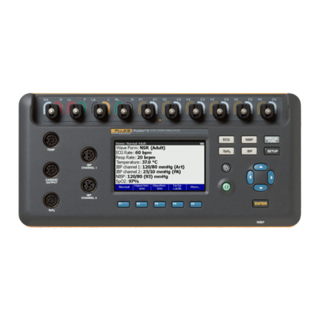
Fluke Biomedical ProSim 8 Series Parts list manual
Fluke Biomedical
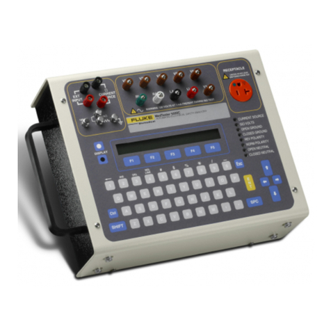
Fluke Biomedical medTester 5000C Operators User manual
