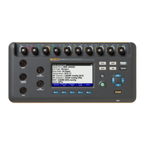
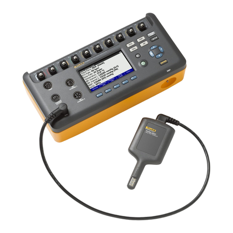
Fluke Biomedical IMPULSE 6000D User manual

Demo Instructions
1
Warning: defibrillators/external pacemakers are capable of emitting lethal
high voltages/energies and should be operated only by trained professionals.
IMPULSE 6000D/7000DP DEFIBRILLATOR/TRANSCUTANEOUS
PACER ANALYZER
INTRODUCTION
25 reasons to differentiate Impulse 6000D/7000DP from all others
Function
1. Compatible with full range of defibrillation technologies (monophasic, bi-phasic and
pulsed bi-phasic) in the healthcare market
2. First-class measurement accuracy
3. Physiological ECG waveforms to test different AEDs
4. User-selectable pacer measurement algorithms for testing wide range of brand
selections
5. Full compliment of built-in pacer testloads (from 50 to 1,500 ohms)
6. Flexible heart-rate setting facilitates rate meter & alarm testing (1 BPM per step)
7. Easy-to-use connection posts for 12 Lead ECG (10 electrodes)
8. Wide range of Arrhythmia selections
9. Auto-range defib & pacer measurement using DSP technology
10. Optional Ansur PC software for automation and standardization or test procedures, as
well as print and data management/storage
11. Ready for external multiple patient defibrillation test loads (25 to175 ohms)
(optional, available Q4, 2007)
12. Very low inductance (<2uH) test resistor
Ergonomics
1. Portable and easy to carry
2. Rugged design
3. Intuitive user interface
4. Backlight, easy-to-read display
5. Large LCD with big numbers
6. USB port
7. Long-lasting, rechargeable NiMH battery
8. Modern, eye-catching new packaging by mechanical & industrial designers design
Other Features
1. DSP (Digital Signal Processor) based measurement
2. Safety standard compliance (IEC 61010): total electrical isolation

Demo Instructions
2
Warning: defibrillators/external pacemakers are capable of emitting lethal
high voltages/energies and should be operated only by trained professionals.
3. Future upgradeable: firmware, software and new waveforms
4. Global support network
Low level ECG
Power switch
Navigator
Function
Pacemaker
input (50 to
1500 ohms)
t
LCD
1) Plug-in defib. paddle contact plates.
(Removable to expose 4mm safety jacks)
2) Main 50-ohm testload input for both external defibrillator
& pacemaker.
Device
selection
Backlight

Demo Instructions
3
Warning: defibrillators/external pacemakers are capable of emitting lethal
high voltages/energies and should be operated only by trained professionals.
SETUP INFO
1. Momentarily press and then release the “POWER ON” pushbutton. The main menu
appears on the analyzer’s display. The battery ICON in the upper-right of the display
indicates the relative charge level of the analyzer’s internal battery. (If ICON is showing
less than 2 vertical bars, connect analyzer to the supplied power supply and plug into
mains/power receptacle.
2. Select the SETUP button to view setup info.
a. F1: BATTERY status to show how much battery left
b. F2: DISPLAY
c. F3: SOUND
d. F4: MORE

Demo Instructions
4
Warning: defibrillators/external pacemakers are capable of emitting lethal
high voltages/energies and should be operated only by trained professionals.
3. To set up unit for test, apply ECG leads to the ten AHA (color on the left side of the
post) and IEC (color on the right) color-coded safety terminals as appropriate.

Demo Instructions
5
Warning: defibrillators/external pacemakers are capable of emitting lethal
high voltages/energies and should be operated only by trained professionals.
DEFIBRILLATION TESTS
THE ENERGY TEST
1. Select DEFIB mode on the left panel, then select a test.
a. Press F1 ENERGY
b. Press F1 Set Wave and then select VFib” from list using the UP/DOWN keys
c. Press F2 Wave Conversion and select “convert” from list using the UP/DOWN
keys
2. Place the defibrillator paddles securely on the analyzer contact plates to discharge the
defibrillator or use Optional Accessories (disposable pad adapters) by removing the two
defib paddle plug-in plates.

Demo Instructions
6
Warning: defibrillators/external pacemakers are capable of emitting lethal
high voltages/energies and should be operated only by trained professionals.
3. The analyzer calculates the energy delivered over the load resistance and displays the
result in joules under the result. Press F4 for summary
4. Show on the monitor that ECG waveform is converted from V. Fib. to Normal Sinus
Rhythm. .
Ventricular Fibrillation Normal Sinus Rhythm
5. Following the same procedures if testing an AED (Automated External Defibrillator

Demo Instructions
7
Warning: defibrillators/external pacemakers are capable of emitting lethal
high voltages/energies and should be operated only by trained professionals.
THE SYNCHRONIZATION TEST (Cardioversion)
Measures the time delay in milliseconds (ms) between the peak of the R wave and the
discharging of the defibrillator pulse. A wide range of simulated ECG waveforms are
available in the analyzer for performing this test. Atrial fibrillation (AFIB) is the most
representative clinical waveform for demonstration purposes. Two selections are
available; AFIB-Coarse is the default simulation.
1. Press F2“Sync”
2. Press F1 “Set Wave” Use UP/DOWN arrow keys to select an ECG waveform. AFIB
is chosen for the purpose of this demonstration.
3. Note ability to change AMPLITUDE and RATE. Select F5 for DONE.
4. Select F2 to select WAVE CONVERSION. Three choices are listed: CONVERT, NO
CONVERT and ASYSTOLE. Convert is chosen for the purpose of this demonstration

Demo Instructions
8
Warning: defibrillators/external pacemakers are capable of emitting lethal
high voltages/energies and should be operated only by trained professionals.
5. Power on the defibrillator. Select the desired energy, place the paddles and discharge.
Note for the purpose of this demonstration, AFIB is converted to a normal heart
waveform.
Atrial Fibrillation Normal Sinus Rhythm
a. Notice the results screen on the Impulse 6000D/7000DP (delay time, etc).

Demo Instructions
9
Warning: defibrillators/external pacemakers are capable of emitting lethal
high voltages/energies and should be operated only by trained professionals.
THE CHARGE TIME TEST
Tests the batteries and charging capacity in the defibrillator
1. Select F3 for CHARGE TIME test.
2. Select F3 for MEASURE
a. Notice CHARGE TIME screen counting down “5-4-3-2-1”
3. Select desired energy level and then charge defibrillator.rillator when the count reaches
zero and the internal beeper sounds... When the selected energy level is reached,
discharge the paddles.
a. Notice the results screen “CHARGE TIME = ___ s”. Please note that typical
charge times are under 10 seconds.

Demo Instructions
10
Warning: defibrillators/external pacemakers are capable of emitting lethal
high voltages/energies and should be operated only by trained professionals.
PACER TESTS
Tests wide range of transcutaneous pacemakers; measures and displays pacer pulse
amplitude, rate, width and energy. Conducts demand and sensitivity tests, measures and
displays refractory periods, etc.
1. Connect pacer to the analyzer through either defibrillator input (50 ohms only) or pacer
input (50 to 1500 ohms)
2. Select PACER mode on the left panel. Select F1 to set the pacer BRAND.
3. Select F2 to select Input Jack options. When defibrillator input is chosen, load is
limited to 50 ohms. If pacer jack input is selected, testload is selectable between 50 to
1500 ohms. Please note that typical pacer outputs are specified at testloads between 50

Demo Instructions
11
Warning: defibrillators/external pacemakers are capable of emitting lethal
high voltages/energies and should be operated only by trained professionals.
and 600 ohms. Select F3 to change pacer loads. Turn pacer on and adjust pacer rate and
output.
8. Observe pacer Measurement result screen
9. Select F4 to view more tests (F1 = SENSITIVITY, F2 = REFRACTORY PERIOD).
Sensitivity test
(Demand sensitivity is the minimal QRS
amplitude (mV) required to cause the
pacer to operate in the demand mode)
Refractory period test
(Measure the time interval in
milliseconds (ms) during which the
pacemaker is insensitive to any
external inputs)

Demo Instructions
12
Warning: defibrillators/external pacemakers are capable of emitting lethal
high voltages/energies and should be operated only by trained professionals.
ECG TESTS
THE ECG MONITOR TEST
1. Select ECG mode on the left panel.
a. “SELECT WAVE TYPE” screen appears
a. F1 = NORMAL SINUS (rates from 30-360 bpm by 1 bpm step),
b. F2 = PERFORMANCE (can choose different wave forms such as square,
pulse, sine and triangle),
c. F3 = PACER INTERACTIVE. Selections Under F3 are:
a. Non-capture: the analyzer operates in “continuous mode”.
However, every 10th pacer pulse is not captured
b. Asynchronous: The heart is totally controlled by the Pacer
c. Non-function: none of pacer pulse is captured by heart
d. Demand: if pacer pulse is higher than heart rate, pacer takes over
heart. If pacer pulse is lower than heart rate, pacer silences.
2. Select F4 for more wave types.
a. Wave types:
a. F1 SUPRA VENTRICULAR

Demo Instructions
13
Warning: defibrillators/external pacemakers are capable of emitting lethal
high voltages/energies and should be operated only by trained professionals.
b. F2 PREMATURE
c. F3 VENTRICULAR
d. F4 MORE
b. Selects F4 again
a. Wave types:
i. F1 CONDUCTION
ii. F2 TV PACED
iii. F3 R WAVE DETECTION
iv. Noise Immunity
For more information, please see the Impulse 6000D/7000DP
Defibrillator/Tranacutaneous Pacemaker Analyzer Getting Started Guide and User
Manual.
Other manuals for IMPULSE 6000D
1
This manual suits for next models
1
Table of contents
Other Fluke Biomedical Medical Equipment manuals
Fluke Biomedical
Fluke Biomedical 7010 User manual
Fluke Biomedical
Fluke Biomedical ProSim 2 User manual

Fluke Biomedical
Fluke Biomedical ProSim 8 Series Parts list manual
Fluke Biomedical
Fluke Biomedical ProSim 8 Series User manual

Fluke Biomedical
Fluke Biomedical 190M III Series User manual

Fluke Biomedical
Fluke Biomedical medTester 5000C Operators User manual