Fluke Biomedical 190M III Series User manual

190M Series III
Medical ScopeMeter
Models 190M-2-III, 190M-4-III
Users Manual
É
FBC-0124 September 2021 Rev. 1(English)
© 2021 Fluke Corporation. All rights reserved.
Specifications are subject to change without notice.
All product names are trademarks of their respective companies.

Warranty and Product Support
Fluke Biomedical warrants this instrument against defects in materials and workmanship for one year from
the date of original purchase OR two years if at the end of your first year you send the instrument to a Fluke
Biomedical service center for calibration. You will be charged our customary fee for such calibration. During
the warranty period, we will repair or at our option replace, at no charge, a product that proves to be defective,
provided you return the product, shipping prepaid, to Fluke Biomedical. This warranty covers the original
purchaser only and is not transferable. The warranty does not apply if the product has been damaged by
accident or misuse or has been serviced or modified by anyone other than an authorized Fluke Biomedical
service facility. NO OTHER WARRANTIES, SUCH AS FITNESS FOR A PARTICULAR PURPOSE, ARE
EXPRESSED OR IMPLIED. FLUKE SHALL NOT BE LIABLE FOR ANY SPECIAL, INDIRECT, INCIDENTAL OR
CONSEQUENTIAL DAMAGES OR LOSSES, INCLUDING LOSS OF DATA, ARISING FROM ANY CAUSE OR
THEORY.
This warranty covers only serialized products and their accessory items that bear a distinct serial number tag.
Recalibration of instruments is not covered under the warranty.
This warranty gives you specific legal rights and you may also have other rights that vary in different
jurisdictions. Since some jurisdictions do not allow the exclusion or limitation of an implied warranty or of
incidental or consequential damages, this limitation of liability may not apply to you. If any provision of this
warranty is held invalid or unenforceable by a court or other decision-maker of competent jurisdiction, such
holding will not affect the validity or enforceability of any other provision.
7/07

Notices
All Rights Reserved
©Copyright 2021, Fluke Biomedical. No part of this publication may be reproduced, transmitted, transcribed, stored in a
retrieval system, or translated into any language without the written permission of Fluke Biomedical.
Copyright Release
Fluke Biomedical agrees to a limited copyright release that allows you to reproduce manuals and other printed materials
for use in service training programs and other technical publications. If you would like other reproductions or distributions,
submit a written request to Fluke Biomedical.
Unpacking and Inspection
Follow standard receiving practices upon receipt of the instrument. Check the shipping carton for damage. If damage is
found, stop unpacking the instrument. Notify the carrier and ask for an agent to be present while the instrument is
unpacked. There are no special unpacking instructions, but be careful not to damage the instrument when unpacking it.
Inspect the instrument for physical damage such as bent or broken parts, dents, or scratches.
Technical Support
For application support or answers to technical questions, either email techservices@flukebiomedical.com or call
1-800- 850-4608 or 1-440-248-9300 (Europe +31-40-2965314).
Claims
Our routine method of shipment is via common carrier, FOB origin. Upon delivery, if physical damage is found, retain all
packing materials in their original condition and contact the carrier immediately to file a claim. If the instrument is delivered
in good physical condition but does not operate within specifications, or if there are any other problems not caused by
shipping damage, please contact Fluke Biomedical or your local sales representative.
Returns and Repairs
Return Procedure
All items being returned (including all warranty-claim shipments) must be sent freight-prepaid to our factory location.
When you return an instrument to Fluke Biomedical, we recommend using United Parcel Service, Federal Express, or Air
Parcel Post. We also recommend that you insure your shipment for its actual replacement cost. Fluke Biomedical will not
be responsible for lost shipments or instruments that are received in damaged condition due to improper packaging or
handling.
Use the original carton and packaging material for shipment. If they are not available, we recommend the following guide
for repackaging:
• Use a double–walled carton of sufficient strength for the weight being shipped.
• Use heavy paper or cardboard to protect all instrument surfaces. Use nonabrasive material around all projecting parts.
• Use at least four inches of tightly packed, industry-approved, shock-absorbent material around the instrument.
Returns for partial refund/credit:
Every product returned for refund/credit must be accompanied by a Return Material Authorization (RMA) number,
obtained from our Order Entry Group at 1-440-498-2560.
Repair and calibration:
To find the nearest service center, go to www.flukebiomedical.com/service or
To ensure the accuracy of the Product is maintained at a high level, Fluke Biomedical recommends the product be
calibrated at least once every 12 months. Calibration must be done by qualified personnel. Contact your local Fluke
Biomedical representative for calibration.
In the U.S.A. and Asia:
Fluke Biomedical
Tel: 1-833-296-9240
Email: [email protected]
In Europe, Middle East, and Africa :
Eindhoven Calibration Lab
Tel: +31-40-2675300
Email: [email protected]

Certification
This instrument was thoroughly tested and inspected. It was found to meet Fluke Biomedical’s manufacturing
specifications when it was shipped from the factory. Calibration measurements are traceable to the National Institute of
Standards and Technology (NIST). Devices for which there are no NIST calibration standards are measured against in-
house performance standards using accepted test procedures.
WARNING
Unauthorized user modifications or application beyond the published specifications may result in electrical shock hazards
or improper operation. Fluke Biomedical will not be responsible for any injuries sustained due to unauthorized equipment
modifications.
Restrictions and Liabilities
Information in this document is subject to change and does not represent a commitment by Fluke Biomedical. Changes
made to the information in this document will be incorporated in new editions of the publication. No responsibility is
assumed by Fluke Biomedical for the use or reliability of software or equipment that is not supplied by Fluke Biomedical, or
by its affiliated dealers.
Manufacturing Location
The 190M Series III Medical ScopeMeter is manufactured for Fluke Biomedical, 6920 Seaway Blvd., Everett, WA, U.S.A.

i
Table of Contents
Title Page
Introduction.......................................................................................................... 1
Contact Fluke Biomedical.................................................................................... 2
Safety Information ............................................................................................... 2
Specifications ...................................................................................................... 2
Unpack the Test Tool Kit ..................................................................................... 2
How to Use the Test Tool .................................................................................... 4
Test Tool Power ........................................................................................... 4
Test Tool Reset ............................................................................................ 4
Menus........................................................................................................... 5
Key Illumination ............................................................................................ 6
Input Connections......................................................................................... 7
Scope .................................................................................................... 7
Probe Type Setup......................................................................................... 8
Input Channel Selection ............................................................................... 9
View an Unknown Signal with Connect-and-View™ .................................... 9
Automatic Scope Measurements.................................................................. 10
Freezing the Screen ..................................................................................... 11
Average, Persistence and Glitch Capture .................................................... 11
Using Average for Smoothing Waveforms ............................................ 11
Smart Average....................................................................................... 12
Persistence, Envelope and Dot-Join to View Waveforms ..................... 12
Glitch Display......................................................................................... 13
High Frequency Noise Suppression...................................................... 13
Waveform Acquisition................................................................................... 14
Set the Acquisition Speed and Waveform Memory Depth .................... 14
AC-Coupling Selection .......................................................................... 14
Reversing the Polarity of the Displayed Waveform ............................... 15
Variable Input Sensitivity ....................................................................... 15
Noisy Waveforms .................................................................................. 16
Mathematic Functions +, -, x, XY-mode ................................................ 16
Mathematic Function Spectrum (FFT)................................................... 17
Waveform Comparisons ........................................................................ 18

ii
190M Series III
Users Manual
Pass - Fail Tests............................................................................................ 20
Waveform Analysis........................................................................................ 20
Automatic Meter Measurements (190M-4-III)................................................ 20
Meter Measurement Selection ............................................................... 20
Relative Meter Measurements ............................................................... 21
Multimeter Measurements (190M-2-III) ......................................................... 23
Meter Connections ................................................................................. 23
Resistance Value Measurement ............................................................ 23
Current Measurement ............................................................................ 24
Auto/Manual Range Selection................................................................ 25
Relative Meter Measurements ............................................................... 26
Recorder Functions .............................................................................................. 27
Recorder Main Menu..................................................................................... 27
Measurements Over Time (TrendPlot™) ...................................................... 27
TrendPlot Function ................................................................................. 27
Recorded Data Display .......................................................................... 28
Recorder Options ................................................................................... 28
Turn Off the TrendPlot Display............................................................... 29
Recording Scope Waveforms In Deep Memory (Scope Record).................. 29
Starting a Scope Record Function ......................................................... 29
Recorded Data Display .......................................................................... 30
Scope Record in Single Sweep Mode.................................................... 30
Triggering to Start or Stop Scope Record .............................................. 30
TrendPlot or Scope Record Analysis............................................................. 31
Replay, Zoom and Cursors................................................................................... 31
Replay the 100 Most Recent Scope Screens................................................ 32
Replay Step-by-Step .............................................................................. 32
Replay Continuously .............................................................................. 33
Turn Off the Replay Function ................................................................. 33
Capturing 100 Intermittent Signals Automatically................................... 33
Zoom on a Waveform.................................................................................... 33
Cursor Measurements................................................................................... 34
Horizontal Cursors on a Waveform ........................................................ 34
Vertical Cursors on a Waveform ............................................................ 35
Cursors on a Mathematical Result (+ - x) Waveform ............................. 36
Cursors on Spectrum Measurements..................................................... 36
Rise Time Measurements ...................................................................... 37
Waveform Triggers ............................................................................................... 38
Trigger Level and Slope ................................................................................ 38
Trigger Delay or Pre-Trigger.......................................................................... 39
Automatic Trigger Options............................................................................. 40
Edge Triggers................................................................................................ 41
Noisy Waveform Triggers....................................................................... 41
Single Event Acquisition......................................................................... 42
N-Cycle Trigger ...................................................................................... 42

Medical ScopeMeter
Table of Contents
iii
External Waveform Triggers (190M-2-III) ..................................................... 43
Pulse Triggers .............................................................................................. 44
Narrow Pulses ....................................................................................... 44
Missing Pulses....................................................................................... 45
Memory and PC................................................................................................... 46
USB Ports..................................................................................................... 46
USB Drivers.................................................................................................. 47
Save and Recall ........................................................................................... 47
Save Screens with Associated Setups ......................................................... 49
All Memories in Use............................................................................... 49
Editing Names ....................................................................................... 50
Save Screens in .bmp Format (Print Screen)............................................... 50
Delete Screens with Associated Setups....................................................... 51
Recall Screens with Associated Setups ....................................................... 51
Recall a Setup Configuration........................................................................ 52
View Stored Screens .................................................................................... 52
Rename Stored Screens and Setup Files .................................................... 53
Copy/Move Stored Screens and Setup Files................................................ 53
FlukeView™ 2 Software ............................................................................... 54
Computer Connection................................................................................... 54
WiFi Connection ........................................................................................... 55
Tips...................................................................................................................... 56
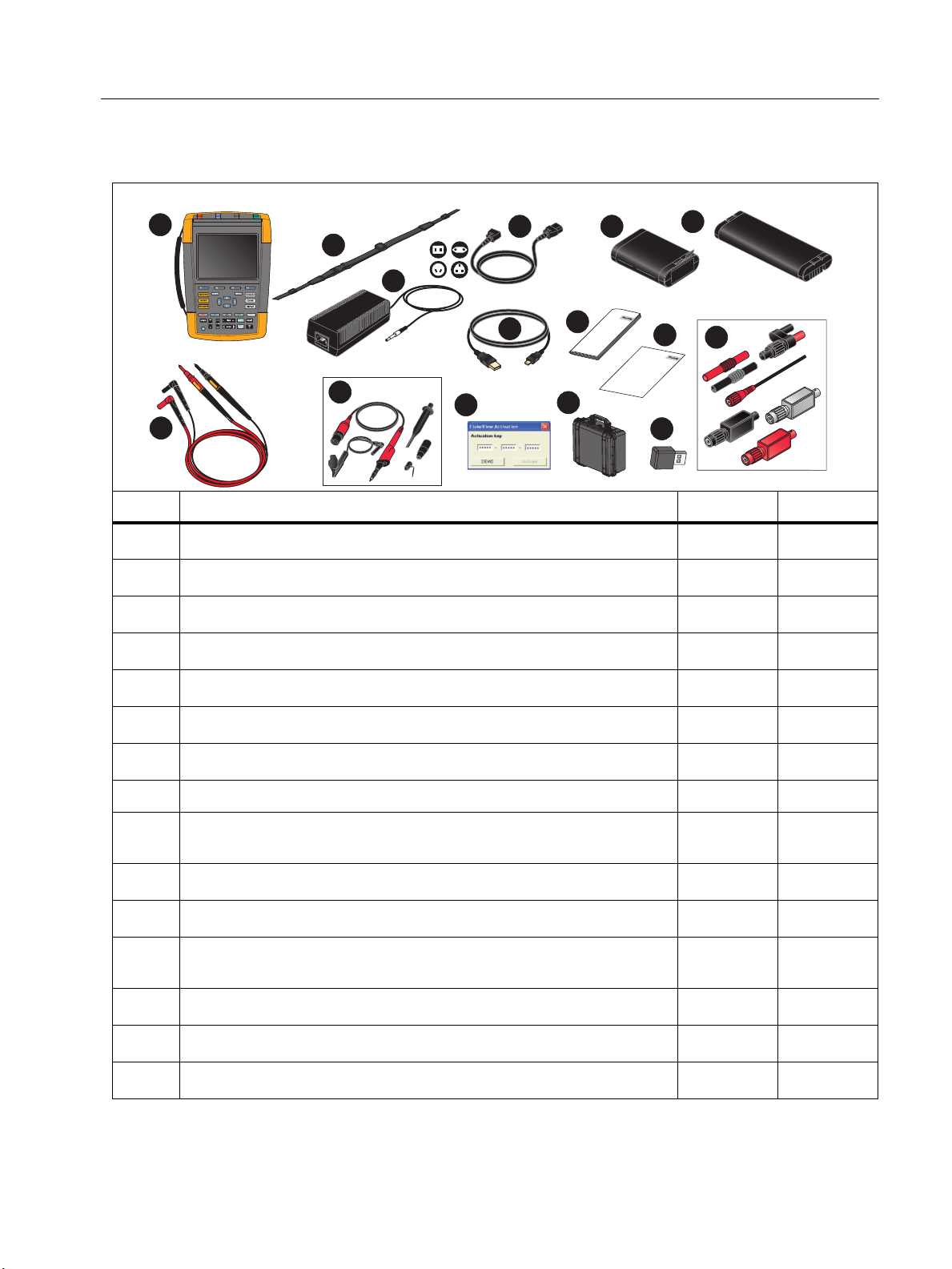
Standard Accessories................................................................................... 56
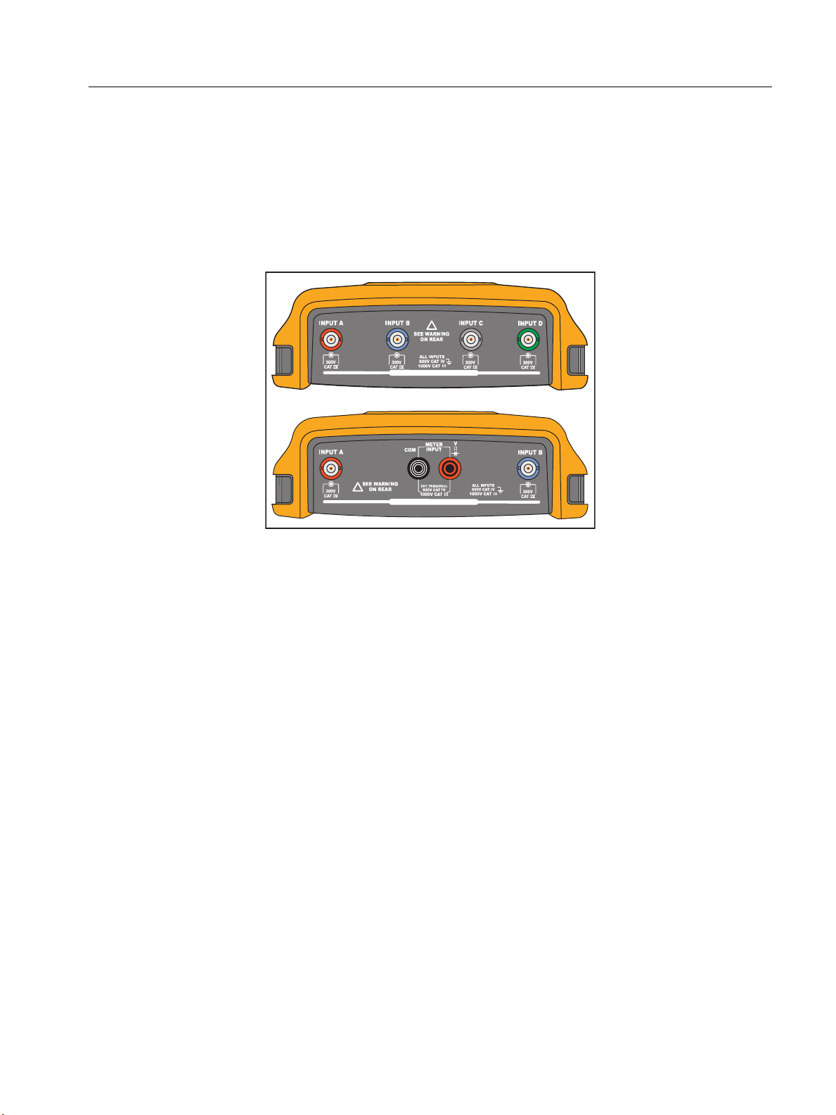
Independently Floating Isolated Inputs......................................................... 57
Tilt Stand ...................................................................................................... 61
Kensington®Lock ......................................................................................... 62
Hangstrap ..................................................................................................... 62
Reset the Test Tool ...................................................................................... 62
Language Setup ........................................................................................... 63
Brightness..................................................................................................... 63
Date and Time .............................................................................................. 63
Battery Life ................................................................................................... 64
Power Down Timer ................................................................................ 64
Display AUTO-off Timer ........................................................................ 64
Auto Set Options .......................................................................................... 65
Maintenance ........................................................................................................ 66
Storage ......................................................................................................... 66
Li-ion Battery Pack ....................................................................................... 66
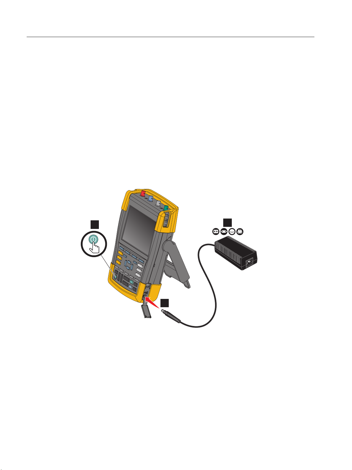
Charging the Batteries........................................................................... 67
Battery Pack Replacement.................................................................... 68
Voltage Probe Calibration............................................................................. 70
Version and Calibration Information ............................................................. 71
Battery Information ....................................................................................... 72
Replacement Parts ....................................................................................... 72
Optional Accessories.................................................................................... 73
Troubleshooting............................................................................................ 75

iv
190M Series III
Users Manual

1
Introduction
The Medical ScopeMeter 190M Series III (the Product or test tool) are high performance
handheld oscilloscopes for troubleshooting industrial electrical or electronic systems. The
descriptions and instructions in this manual apply to all versions. The available versions are:
• 190M-2-III
Two 200 MHz Scope Inputs (BNC), one Meter Input (banana jack)
• 190M-4-III
Four 200 MHz Scope Inputs (BNC)
Version 190M-4-III appears in most illustrations.
Only the 190M-4-III version includes Input C and Input D and the Input C and Input D selection
keys (Cand D). C D

190M Series III
Users Manual
2
Contact Fluke Biomedical
Fluke Corporation operates worldwide. For local contact information, go to our website:
www.flukebiomedical.com.
To register your product, view, print, or download the latest manual or manual supplement, go to
our website.
Fluke Biomedical
P.O. Box 9090
Everett, WA 98206-9090
1-800-850-4608 (US toll-free)
1-440-498-2575 (International)
Safety Information
General safety information is in the printed Safety Information document that ships with the
Product and at www.flukebiomedical.com. More specific safety information is listed where
applicable.
Specifications
Complete specifications are at www.flukebiomedical.com. See the 190M Series III Product
Specifications.
Unpack the Test Tool Kit
Tab le 1 is a list of the items included in your Product kit by model type.
Note
Batteries are not installed when you receive your kit. See Battery Pack Replacement for
more information. When new, the rechargeable Li-ion battery is not fully charged. See
Charging the Batteries.

Medical ScopeMeter
Unpack the Test Tool Kit
3
Table 1. Kit: 190M III Models
Item Description 190M-2-III 190M-4-III
Test Tool with Handstrap ••
Hangstrap ••
BC190/830 Power Adapter/Charger ••
Universal Power Cord Set ••
BP290 Li-ion Battery, single capacity •
BP291 Li-ion Battery, dual capacity •
TL175 Test Lead Set •
VPS410-II-x Voltage Probe 500 MHz, 10:1 24
USB interface cable for PC connection
(USB-A to mini-USB-B) ••
Safety Information ••
FlukeView 2 Demo Software and Installation Instructions ••
FlukeView Software for Windows activation key (converts
FlukeView 2 DEMO status into Full Version status) ••
CXT293 Protective Carry Case ••
WiFi Adapter (DWA131) ••
MA190 Medical Applications Accessory Kit ••
TEST
25%
50%
75%
100%
1
2
911
12
14
5
d
VPS410-II-x
8
7
6
3
4
13
10
15

190M Series III
Users Manual
4
How to Use the Test Tool
This section provides a step-by-step introduction to the scope and meter functions of the test
tool. The introduction does not cover all of the capabilities of the functions but gives basic
examples to show how to use the menus and perform basic operations.
Test Tool Power
See Figure 1 to power the test tool from a standard ac outlet. See Battery Life for instructions on
using battery power.
Turn on the test tool with O.
The test tool powers up in the last setup configuration.
The menus to adjust date, time, and information language are switched on automatically when
the test tool is powered on for the first time.
Figure 1. Powering the Test Tool
Test Tool Reset
To reset the test tool to the factory settings:
1. Turn the test tool off.
2. Press and hold U.
3. Press and release O.
The test tool turns on. Wait to hear a double beep that indicates the reset is successful.
4. Release U.
3
2
1

Medical ScopeMeter
How to Use the Test Tool
5
Menus
The Scope menu is the default menu when you turn on the test tool. The following example
shows how to use the menus to select a function.
To open the Scope menu and to choose an item:
1. Press Pto show the labels that define the present use for the four blue function keys
near the bottom of the screen.
2. Open the Waveform Options menu.
The menu shows at the bottom of the screen. Actual settings are shown on a yellow
background. Use the cursor to change the setting (black background) and confirm the
selection with E. See Figure 2.
Figure 2. Basic Navigation
3. Use the blue arrow keys to highlight the item.
4. Press Eto accept the selection.
The next option will be selected. After the last option the menu will be closed.
Note
To exit the menu at any moment press CLOSE.
5. Press Ito close a menu.
EEE
P
4
fg
h
i
3a
3a
1
23b 3b 3b

190M Series III
Users Manual
6
Key Illumination
Some keys are provided with an illumination LED. For an explanation of the LED function, see
Tab le 2 .
Table 2. Keys
Item Description
OOn: The display is off, test tool is running. See Display AUTO-off Timer.
Off: in all other situations
HOn: Measurements are stopped, the screen is frozen. (HOLD)
Off: Measurements are running. (RUN)
A/
B/
C/
D
On: The range key, the move up/down key, and the F1-4 key labels, apply to the
illuminated channel key(s).
Off: -
J
On: Manual operating mode.
Off: Automatic operating mode, optimizes the waveform position, range, time base
and triggering (Connect-and-View™)
T
On: Signal is triggered
Off: Signal is not triggered
Flashing: waiting for a trigger at Single Shot or On Trigger waveform update.

Medical ScopeMeter
How to Use the Test Tool
7
Input Connections
The top of the test tool has four safety BNC signal inputs (model 190M-4-III) or two safety BNC
jack inputs and two safety 4-mm banana jack inputs (model 190M-2-III). These isolated inputs
allow independent floating measurements with each input. The banana jack inputs (model
190M-2-III) can be used for DMM measurements or can be used as External Trigger input for the
Scope mode. See Figure 3.
Figure 3. Measurement Connections
Note
To maximize the benefit of independent isolated floating inputs and to avoid problems
caused by improper use, see Tips.
For an accurate indication of the measured signal, you must match the probe to the input
channel on the test tool.
When using probes that are not included with the Product, see Voltage Probe Calibration.
Scope
To make scope measurements:
1. Connect the red voltage probe to input A, the blue voltage probe to input B, the gray voltage
probe to input C, and the green voltage probe to input D.
2. Connect the short ground leads of each voltage probe to its own reference potential. See
Figure 4.
ALL INPUTS ISOLATED
!
ALL INPUTS ISOLATED
!

190M Series III
Users Manual
8
Figure 4. Scope Connections
XW Warning
To prevent electrical shock, use the insulation sleeve when you connect the
VPS410 Probe Set without the hook clip or the ground spring.
Probe Type Setup
To obtain correct measurement results the test tool probe type settings must correspond to the
connected probe types.
To select the input A probe setting:
1. Press Ato show the INPUT A key labels.
2. Press 3to open the PROBE ON A menu.
3. Use the cursor and Eto select the probe type Voltage, Current, or Temp.
a. Voltage: select the voltage probe attenuation factor.
b. Current and Temp: select the current probe or temperature probe sensitivity.

Medical ScopeMeter
How to Use the Test Tool
9
Input Channel Selection
To select an input channel:
1. Press the required channel key (A-D):
• the channel is turned on
• the channel key illumination is turned on
2. If the channel key is illuminated, Land Kare now assigned to the indicated channel.
To set multiple channels to the same range (V/div) as, for example, input A, do the following:
1. Select the input A measurement function, probe setting and input options for all involved
channels.
2. Press and hold A.
3. Press Band/or Cand/or D.
4. Release A.
Notice that all pressed keys are illuminated now.
Land Kapplies to all involved input channels.
View an Unknown Signal with Connect-and-View™
The Connect-and-View™ feature lets the test tool show complex, unknown signals automatically.
This function optimizes the position, range, time base, and triggering and assures a stable
display of virtually any waveform. If the signal changes, the setup is automatically adjusted to
maintain the best display result. This feature is especially useful for quickly checking several
signals.
To enable the Connect-and-View feature when the test tool is in MANUAL mode:
1. Press Jto perform an Auto Set. AUTO appears at the top right of the screen, the key
illumination is off.
The bottom line shows the range, the time base, and the trigger information. The waveform
identifier (A) is visible on the right side of the screen. See Figure 5. The input A zero icon - at
the left side of the screen identifies the ground level of the waveform.
2. Press Ja second time to select the manual range again. MANUAL appears at the top
right of the screen, the key illumination is on.

190M Series III
Users Manual
10
Figure 5. The Screen After an Auto Set
Use LKN V at the bottom of the keypad to change the view of the waveform
manually.
Automatic Scope Measurements
The test tool offers a wide range of automatic scope measurements. In addition to the waveforms
you can show four numeric readings: READING 1 - 4. These readings are selectable
independently, and the measurements can be done on the input A, input B, input C or input D
waveform.
To choose a Peak-Peak measurement for Input A, do the following:
1. Press Pto show the SCOPE key labels.
2. Open the READING menu with 2.
3. Select the reading number with 1, for example READING 1.
4. Use the cursor and Eto select on A. Observe that the highlight jumps to the present
measurement.
5. Use the cursor and Eto select the Hz measurement.
Observe that the top left of the screen shows the Hz measurement. See Figure 6.
To choose also a frequency measurement for Input B as second reading:
1. Press Pto show the SCOPE key labels.
2. Open the READING.. menu with 2.
3. Select the reading number with 1, for example READING 2.
4. Use the cursor and Eto select on B. The highlight jumps to the measurements field.
5. Use the cursor and Eto open the PEAK menu.
6. Use the cursor and Eto select the Peak-Peak measurement.

Medical ScopeMeter
How to Use the Test Tool
11
Figure 6 shows an example of the screen with two readings. The character size will be reduced
when more than two readings are on.
Figure 6. Hz and V peak-peak as Scope Readings
Freezing the Screen
You can freeze the screen (all readings and waveforms) at any time.
1. Press Hto freeze the screen. HOLD appears at the right of the reading area. The key
illumination is on.
2. Press Hagain to resume your measurement. The key illumination is off.
Average, Persistence and Glitch Capture
Using Average for Smoothing Waveforms
To smooth the waveform:
1. Press Pto show the SCOPE key labels.
2. Open the WAVEFORM OPTIONS menu with 4.
3. Use gfto jump to Average:.
4. Use the cursor and Eto select On... to open the AVERAGE menu.
5. Use the cursor and Eto select Average factor: Average 64. This averages the
outcomes of 64 acquisitions.

190M Series III
Users Manual
12
6. Use the cursor and Eto select Average: Normal (normal average) or Smart (smart
average, see below).
You can use the average functions to suppress random or uncorrelated noise in the waveform
without loss of bandwidth. Waveform samples with and without smoothing are shown in Figure 7.
Smart Average
In the normal average mode occasional deviations in a waveform just distort the averaged wave
shape, and do not show up on screen clearly. When a signal really changes, for instance when
you probe around, it takes quite some time before the new wave shape is stable. With smart
averaging you can quickly probe around, and incidental waveform changes like a line flyback in
video show up on screen instantly.
Figure 7. Smoothing a Waveform
Persistence, Envelope and Dot-Join to View Waveforms
You can use Persistence to observe dynamic signals. See Figure 8.
1. Press Pto show the SCOPE key labels.
2. Open the WAVEFORM OPTIONS menu with 4.
3. Use the cursor and Eto highlight to Waveform: and open the Persistence... menu.
4. Use the cursor and Eto select:
a. Digital Persistence: Short, Medium, Long or Infinite to observe dynamic waveforms like on
an analog oscilloscope.
b. Digital Persistence: Off, Display: Envelope to see the upper and lower boundaries of
dynamic waveforms (envelope mode).
This manual suits for next models
2
Table of contents
Other Fluke Biomedical Medical Equipment manuals

Fluke Biomedical
Fluke Biomedical ProSim 8 Series User manual

Fluke Biomedical
Fluke Biomedical ProSim 2 User manual

Fluke Biomedical
Fluke Biomedical IMPULSE 6000D User manual

Fluke Biomedical
Fluke Biomedical ProSim 8 Series Parts list manual

Fluke Biomedical
Fluke Biomedical medTester 5000C Operators User manual

Fluke Biomedical
Fluke Biomedical 7010 User manual