Fluke PM6685 User manual

Connect and Go!
FLUKE PMS6SS
FLUKE

Contents
Introduction 2
Getting familiar with the front panel 4
Exercises 6
Measuring 7
Trying the front panel keys 11
Aux Menu 16
Is it really this easy? 20
4822 872 20032
Rev. 5, February 2002
©Pendulum Instruments, Sweden
Printed In Sweden

The PM6685 and PM6685R are powerful frequency coun-
ters, yet easier to use. The difference between the models
is that the PM6685R includes aRubidium timebase oscilla-
tor, an extremely accurate “atomic dock”. The PM6685R
ishoused in abigger cabinet than PM6685, but the opera-
tions of both instruments are identical. This manual gives a
brief description of some functions and keys of your new in-
strument, to get you started.
Frequency Measurements, the easy way!
Making measurements is very easy, just connect and go!
Page 2

Pw.cj.q ON &
STAND.ay^,;^
/W
Read the frequency of the signal
The counter measures immediately
AND and the settings are optimized for
your signal
GO!
If
IL
FREQA'
nnnngh.
uuuu
MW '“I auto i
TRIG '»»•*
EVEL A
1
Result Signal level
Continue to read and exercise if you want to know more
about the possibilities with this PM6685, 300 MHz Fre-
quency Counter. The 15 to 25 minutes it takes are well
spent. When you want deeper knowledge, the Operators
Manual Is there to help you.
Page 3

Getting Familiar with the Front Panel
You will reach most of the powerful features of the fre-
quency counter by pressing akey. Look at the picture be-
low and you will find the logic of the front panei.
FUNCTION SELECTION .
The FUNCTION rocker key scrolls left or ^
through the measuring functipns. 1,
The MENU key turns on all function indicoiprs on
the front panel. {Some people find It easier to use it .f^^ssuremehts., ,|
this way).
^The AUX MENU key lets you access additional ad- ^\
:,vanced,functionsv' -\
MEASURING TIME
Controls the rate i
and resplutlon of
FLUKE
INPUT SETTING KEYS
Use these keys to set the irri-V'
pedance, trigger level or sen-
sitivity, for the Ainput, or to :
select alowpass filter. The '
current, state of each setting is
shown on the display right
aboye the corresponding key.
The Cinput is fully automatic
and no. settings are required;
AUTO KEY
Apress on the
AUTO key turns
on the AUTO
function. It will
optimize the inr ,
put settings for :
.almost every ..
measurement-
DATA ENTRY KEYS
,Use these keys to
increase or de-
,
•
'crease values for 2!
measuring timb'
constants, etc; .
Press the ENTER
key to.Qonfirm
lections2®ve'ii'':;nS5
made;

MEASURED VALUE
The measured value is
displayed with ten big
clear digits
1
1|ii^ 1^ gjOVERFLOW SINGLE
j
1U.U uuuuuuu“erv
FREOA FREQC PER A RATIO A/E RATIO C/A PWIDTHA TOIA-MAN.. MU.IXJE.A SIAi...S,TQ;l,
REMO'"E EXT REF CHECK FIITER 150Mii 1=03 AUTO ||LEVEL ASENSITIVITY A|i
SRQ LOBAT OVERLOAD HOLD NULL OFFSET TRIG'
—
fSS-S liSM-BiS'S S'S StS'8'|-8’^ J
BAR GRAPH INDICATOR FOR INPUT LEVEL OR SENSITIVITY
The bar graph on the display shows the signal level or sensitivity.
When AUTO is enabled the bar graph shows the signal level and
when disabled i,
The display on PM6685/pm6685R.
Page 5

Exercises
nis much more fun to push
measure. You can ^ther press ^connect
counter measure on the intern p^-cioa wia aBNC ca-
ssf&:s=s
functions.
ISet up the Generator; iFreguencYL 12 kHz {
Sauare,,...... _...!
I'50% !
I!
Ahand in the margin points out the exercises.
Basic Startup of
the Counter
ing from aknown state is always easier. To do so, just
the power off and then on again. recalls
sing local/preset and then ENTER also recalls
.14. r./rvt+inOC

Measuring
Connect the output of the generator to input Aof the coun-
ter and you wii! immediately see the measured frequency
on the display, Note the high resolution, Nine digits are dis-
played in ameasuring time of only 200 ms. The following
section is ashort description on how to use the keys and
the functions for setting the input.
Input settings
01^ AUTO function
AUTO The built-in AUTO function makes the use of PM6685 easy.
The peak to peak voltage is measured and Auto sets the
hysteresis band between 1/3 and 2/3.
You’ll soon find that it’s much easier, and more accurate to
measure with the AUTO function on, than to do manual set-
tings. There are just afew exceptions that needs manual set-
tings -AM-moduiated signals, extremely noisy signals, non-
repetitive signals, and signals with frequencies below 50 Hz.
Level meter
ILB?a.A I
Ifllllllll
lasmv IV lOVlrnis)
lllllll KNSfTftflTV A1}
lamv ISftnV *V W(tBg) ;
The bar graph scale has two functions: It shows the input
level when AUTO is on, and the sensitivity setting when
AUTO is turned off.
Ascale In Vrms is printed on the front panel. One step on
the scale equals 3dB.
Page 7

Vary the signal amplitude and watch the bar graph change.
The following figure illustrates the trigger level or sensitivity
expressed in dBm.
.Z! >am Odlim ismrn
;
I
10
lE^L A
iltilllll
nV lOomV
i,'[iaoDOPocioGyL
tv 10V(Nw41
Waveform compensation and indication
if you want to measure non-symmetrical signals, many
other counters will not trig, The reason for this is that non-
symmetrical signals do not center on OV, but they get adc
shift after the ac coupling capacitor. When the duty factor
exceeds acertaih factor, the input will stop triggering unless
the trigger window is offset to compensate for the dc shift of
the signal.
The grayed fields show the position of the hysteresis band, and
the circles are trigger points^^^ reset points
j
1ri
'riL "•---
1
ac coupling capacitor
Trigger level indica-
tion on the display
Dc shift caused by the ac coupling capacitor.
Set the symmetry on the generator to about 10% and note
that the waveform segment on the display changes. The in-
put detects the duty cycle change and compensate for the
Page 8

new waveform. Set the symmetry to the extreme opposite,
99%, and note that the counter still counts.
%Manual setting
Press the Waveform key once to turn off AUTO and return
to the last manual settings. Press the Waveform key again
to select between the three waveform compensations.
n(0 -25% duty factor)
i 1 I{25 -75% duty factor)
U(75 -100% duty factor)
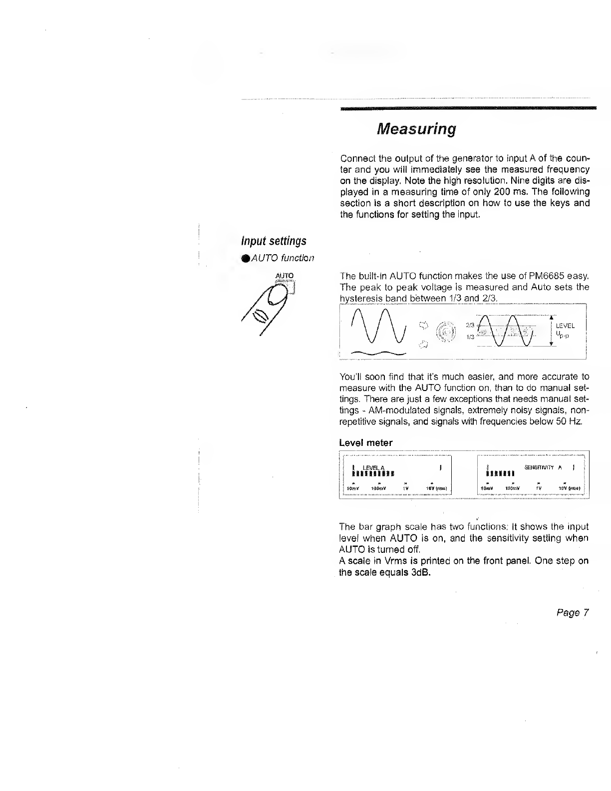
Use the SENS keys to adjust the input sensitivity.
You can read the current sensitivity setting on the bar
graph. _
SENSITIVITY
THE
^!\;
\Ir/ r
Turn on AUTO, and then turn it off again by pressing one of
the SENS keys. This way you freeze the current waveform
selection and sensitivity selected by AUTO.
Pressing SENS again will increase/decrease the sensitivity
around the freezed waveform compensation.
When measuring frequency AUTO sets the sensitivity to 1/3
of the input signal level, to reject noise. When measuring
pulse width, AUTO sets the sensitivity as high as possible
to reduce trigger errors.
Lets check that by turning Auto setting to manual setting.
-Set the generator to 12 kHz sine wave and 3Vrms
(9 Vp-p) output and apply the signal to Input A.
-Select Frequency and AUTO function on the counter. No-
tice the signal level on the bar graph.
Page 9

Press the FILTER key to toggle the built-in 100 kHz LP fil-
ter. The filter segment is on when the filter is being used.
Page 10

Trying the Front Panel keys
On the foliowing pages you will find ashort description on
some keys and functions that you will find on the PM6685.
Try them and watch the display when you are using them.
^Changing Numerical values, such as Measuring Time, Synchronizing
Numerical Values Delay, Nulling reference value etc., can be changed in two
ways:
-in steps of 1-2-5 with coarse adjustment,
^or digit by digit with fine adjustment.
Coarse adjustment
COARSE
W3JUSTMENT T’ II :j
pnn“3
CLI.U
r-r :^-«r
Use the FUNCTION rocker key or the DATA ENTRY keys
to step up or down in steps of 1-2-5, then confirm your se-
lection with ENTER.
Changing to Fine adjustment
Press the SENS key to enter fine adjustment. To return to
coarse adjustment, push the cursor out of the display, to the
left using the SENS key.
Page 1
1

Fine adjustment
FINE 0Select digit
ADJUSTMENT <^
DE13 I
I
?oao nn
uunnnn-3
uuuu
.l/j
QIncrease/Decrease .
digit value
ENTER
©OK! EM
Press the right or left SENS arrow key to select the digit you
want to change, and then press the DATA ENTRY keys to
change the digit value.
The measuring time decides the resolution in the measure-
ment. Increasing the measuring time gives more digits.
Press the iWEAS TIME key and use the FUNCTION rocker
key to change the measuring time in steps of 1-2-5 as
coarse adjustment. Press the WIEAS TIME key again to re-
turn to measuring.
The measuring time can also be fine adjusted, as described
above.
Turn on SINGLE. The result is now from asingle measure-
ment cycle, and the “measuring time" becomes display time
{time between measurements). This gives fast measure-
ments with low resolution.

auJNK
Turn off SINGLE and the counter averages all data cap-
tured during the set measuring time, giving higher resolu-
tion in the result.
NOTE; Prescalers affect the number of input cycles in a
single cycle measurement, see Operators Manual.
Press the BLANK DIGITS key once for each digit you want
to blank out on the display,
I
i_
JSH.3B 16H.
543? 6..
«OI
54.3. &hZ
II i: 54... 6HZ
1x
II IqSHz
X'6Hz
54.3? j6HZ
CHECK
The CHECK key enables a seif-test of the measuring func-
tions. Press the CHECK key to connect internally the
10 MHz reference signal to the logic circuit. Press the
FUNCTION rocker key to scroll through all measuring func-
tions.
Note that if you select FREQ Cwhen check is on, the most
significant digits show the prescaling factor of the optional
Cinput (16, 32 or 256).
Page 13

EXT
REF
NUU
REF !N
.EXT
.J 'REF
f'( '-
I
1
|'SRtMWUii|
1INT —
"
1
'
1
1
1
REF •' Time base
Press the EXT REF key to toggle between the internal or
external 10 MHz time-base. Since no reference signal is
connected the display will show 0-.
Press the NULL key to store the current result as acon-
stant, and switch on the nulling function. The counter will
now show the results as adeviation from the stored con-
stant.
Read about how to change the null value via the AUX
MENU, on page 17 in this manual.
Page 14

Press the DISPLAY HOLD key to hold the current readout
on the display. Press again to continue to measure. When
DISPLAY HOLD is active, anew measurement is made
each time you press RESTART.
•TOTalize AMANuai Function
TOT A MAN
Inp. A
pen/i.^iose
Count. Logic
!Reset
DISPLAY MEAS
HOLD RESTART
I.
This function lets you totalize (count) the number of trigger
events on channel A. Use the DISPL HOLD key to start and
stop totalization, and the MEAS RESTART key to reset the
displayed result.
Try using the counter as astopwatch:
-Turn on CHECK
-Select TOT AMAN using the FUNCTION key
-Press DISPL HOLD to start the stopwatch
The counter will now count to 10000000 in one second.
-Press DISPL HOLD to stop the stopwatch
Divide the reading with 10000000, and you will get the
elapsed time in seconds.
Page 15

AUX MENU
The AUX MENU contains acollection of useful, but less fre-
quently used functions, Here you will try some of the func-
tions, the rest you will find described in the Operators Man-
ual.
AUX
MENU Recail Memory
Save Memory
Protect Memor;}'
Trigger Slope
Arming Start
Arming Stop
Burst CW
Display Light "
NULL•
Display Overflow-
Analog Output-
GPIB-Address
Time Out
Test
Program Version
AUX
MFKJl)
Regard the AUX MENU as arotary switch. Press the AUX
MENU key and then use the FUNCTION rocker to “turn the
rotary switch. When the display shows the function you
want, confirm your selection by pressing ENTER key. To
escape without selecting any auxiliary function, press the
MEAS RESTART key.
Some selections will take you to asubmenu with more se-
lections or parameter settings.
Display Backlight You can turn the backlight on or off in the AUX MENU. This
is useful when the instrument is powered from battery.
^-
jO,OODDDG£]afi-
i-
Page 16

NULL You press the NULL key to store the last measured value
and display the following results as adeviation from this
value. If NULL is on. you switch it off with the NULL key.
You press the AUX MENU key and select NULL to change
this value, or to switch on the NULL function without chang-
ing the stored value.
-Press the AUX MENU key and use the DATA ENTRY
keys to select NULL, and press ENTER.
-You can now see the value stored by the NULL key, press
ENTER if you want to switch on nulling with this value.
FINE
ADJUSTMENT Os
i.
:digit
nnnnnnnnn-3
UU.UUUiUUUU
©increase/Decrease
digit value ©OK
-To change the value, press the SENS arrow keys to select
position for fine adjustment.
-Press the DATA ENTRY keys to change digit value.
-Confirm changes with ENTER, or escape without chang-
ing the nulling value by pressing the MEAS RESTART
key.
You can also use coarse adjustment to change the value.
Position the cursor in the leftmost position and press the left
SENS arrow key to enter coarse adjustment. Pressing ei-
ther of the DATA ENTRY keys to change value in 1-2-5
steps.
Page 17

5ave Vou can store afront panei setting in one of 19 memories.
UporDn Look for Up or Dn
Press the AUX MENU key to enter the menu.
-Press the DATA ENTRY keys to select SAVE.
-Press the ENTER key.
-Select anumber for Memory (for example 4) by press-
ing the DATA ENTRY arrow keys.
-Confirm with ENTER.
Page 18

Recall
0Last setting before
switch off
Your front pane! setting is now stored in memory 4.
Now we want to recall the setting stored in memory 4, but
first you have to change some settings, for example:
-Press the LOCAL/PRESET key followed by the ENTER
key to preset the counter. Check that the counter is set for
another measuring function, FREQ Ainstead of PER A.
To recall the front panel setting with the PER A measuring
function.
-Press the AUX MENU key to enter the menu.
-Press the DATA ENTRY keys to select RECALL.
-Press the ENTER key.
-Select anumber to recall (in this example 4) by press-
ing the DATA ENTRY arrow keys.
-Confirm with the ENTER key.
The stored front panel setting is now recalled and the mem-
ory annunciator is shown on the display.
-Press STAND-BY to turn off the counter.
-Press ON to turn it on again
Note that the memory annunciator is on, if you turn off the
counter when amemory setting is active, the counter auto-
matically recalls that memory at power on instead of start-
ing with its default settings.
Perhaps you by accident turned off the instrument, or wants
to continue ameasurement the following day?
Then, you can return to the last setting before power off, by
recalling memory number 0.
Page 19
Other manuals for PM6685
1
This manual suits for next models
1
Table of contents
Other Fluke Cash Counter manuals