TrueTime 800 Series Configuration guide

800gench1.fm Rev. A 800TCU User’s Guide 1-1
1
General Information
1.1 Scope of Manual
This manual contains the information necessary to operate and maintain a TrueTime 800
Series Time Code Unit (TCU).
1.2 Conventions
The conventions used in this manual are:
Text = Indicates body text
Italics = Emphasizes important information
= Used with bold text to call attention to important information
= Used with bold text to identify potential damage to equipment
= Used with bold text to identify potential injury
text = Used to display output character strings
text =Used to indicate text you should enter with your keyboard,
exactly as printed
This unit may contain Custom Options and/or Configurations. A description
can be found starting on sheet iii of the index. This description may modify or
supersede descriptions or specifications elsewhere in this manual.
Caution
WARNING

1-2 800TCU User’s Guide 800gench1.fm Rev. A
General Information Purpose of Equipment
1.3 Purpose of Equipment
The Model 800 Series is a family of Time Code instruments designed around a versatile
microprocessor. The three basic operating modes of these instruments are:
1. As a Time Code Generator that accumulates time from an entered starting time and
then provides various outputs based on the accumulated time.
2. As a Time Code Translator that deciphers serial time codes from some external source
and provides various outputs based on the decoded time. The Translator operates in
both the forward and reverse directions.
3. As a Synchronized Generator it is derived from the input time code and is
phase-locked to the input code. If the input fails, the generator continues to update
using its time base as the reference. Further, the internal oscillator is disciplined to the
frequency of the input code, which further enhances the performance of the unit during
periods of input code failure.
The various operating modes are optional and are supplied if they are marked (X) in the
Table of Contents.
1.4 Physical Specifications
The physical specifications are:
Height: 1.73 in (4.39 cm)
Width: Suitable for mounting in a standard 19.0 in (48.26 cm)
equipment cabinet
Depth: 14.0 in (35.56 cm) plus mating connectors
Weight: Approximately 10 pounds
1.5 Environmental Specifications
The temperature specifications are:
Operating Temperature: 0 to +50°C (+32 to +122°F)
Storage Temperature: -17 to +100°C (0 to +212°F)
Humidity: To 95% relative, non-condensing
Cooling Mode: Convection

800gench1.fm Rev. A 800TCU User’s Guide 1-3
Power Specifications General Information
1.6 Power Specifications
The input power specifications are:
Voltage: 95 to 260 VAC
Frequency: 47 Hz to 440 Hz
Power: Approximately 15 Watts
1.7 Option Identification
Each of the options that are supplied with this unit are indicated in the Table of Contents
by an (X). Custom Options/Configurations are described on page iii of the manual index.
1.8 Signal Specifications
1.8.1 Generator Specifications
General Specifications, Generator
Days Reset: Resets to day 1 after day 365
Leap Year: Resets to day 1 after day 366
Advance/Retard Rates: 0.5 µs, 1 µs, 10 µs, 100 µs, 1 ms, 10 ms, 100 ms, 500 ms
and 1 second
Front-panel Controls and Indicators:
Operating Mode
Generate Time
Status Messages
Leap Year and Time Base Select
Advance/Retard Rate
External Start
Generate Code
Video Mixer Controls
Front-panel Controls Disable
Start and Stop
Internal Oscillator (STD)
Frequency: 10 MHz
Stability: < 50 PPM, 0 to +50°C
Aging: < 1 PPM/year

1-4 800TCU User’s Guide 800gench1.fm Rev. A
General Information Signal Specifications
Internal Oscillator (TCXO)
Frequency: 10 MHz
Stability: < 0.5x10E-6, 0 to +50°C
Aging: < 1 PPM/year
Internal Oscillator (OCXO)
Frequency: 10 MHz
Stability: < 1x10E-8, 0 to +50°C
Aging: < 2x10E-9/day
External Time Base Input
Frequency: 1 MHz
Amplitude: 0.5 to 10 Vpp
Impedance: 10 kΩto ground
External Start Input
Active Edge: Selectable, rising or falling. Starts on the next edge after
being Armed.
Levels: Logic Zero: 0 ±0.5 VDC
Logic One: >+2.5 VDC, <+5 VDC
Impedance: 4.7 kΩto +5 V
IRIG-B Time Code Output
Amplitude: Adjustable, 0 to 10 Vpp into 600 Ωto ground
Ratio: Adjustable, 2:1 to 5:
NOTE: Rear Panel BNC is typically labeled "GEN
CODE"
Timing Signals
Rates: 1 kPPS, 100 PPS, 10 PPS, 1 PPS
Duty Cycle: 50%
Amplitude: 0 to +5 VDC at ±6 mA
Timing: Rising edge on time

800gench1.fm Rev. A 800TCU User’s Guide 1-5
Signal Specifications General Information
1.8.2 Translator Specifications
General Specifications, Translator
Days Reset: Resets to day 1 after day 365
Leap Year: Resets to day 1 after day 366 on the day armed
Advance/Retard Rate: 0.5 µs, 1 µs, 10 µs, 100 µs, 1 ms, 10 ms, 100 ms, 500 ms
and 1 second
Front-panel Controls and Indicators:
Operating Mode
Translator Time
Status Messages
Leap Year Select
Error Bypass Select
Input Polarity and Filter
Translate Code
Forward/Reverse Translation
Video Mixer Controls
Code Input
Format: Amplitude modulated IRIG-B
Amplitude: 0.1 to 10 Vpp
Bandwidth: 30 Hz to 50 kHz
Ratio: 2:1 to 6:1
Impedance: 100 kΩto ground
Polarity: Selectable, positive or negative
Direction: Selectable, forward or reverse
Error Bypass
Bypass: Selectable, 0 to 9 frames and infinite
Timing Signals
Rates: 1 kPPS, 100 PPS, 10 PPS, 1 PPS
Timing: Rising edge on time
Amplitude: 0 to +5 VDC at ±6 mA
Duty Cycle: Dependent on input code carrier

1-6 800TCU User’s Guide 800gench1.fm Rev. A
General Information Signal Specifications
1.8.3 Synchronized Generator Specifications
General Specifications, Sync Generator
Days Reset: Resets to day 1 after day 365
Leap Year: Resets to day 1 after day 366 on the day armed
Phase Correction: Automatic, 500 ns corrections
Front-panel Controls and Indicators:
Operating Mode
Translator Time and Generator Time
Status Messages
Leap Year and Time Base Select
Error Bypass Select
Prop. Delay, Input Code Polarity and Filter
Sync Gen Input Code and Gen Code
Oscillator Discipline Complete Status
Video Mixer Controls
Auto Advance/Retard Direction and Rate
Code Input, Carrier
Format: Amplitude modulated IRIG-B
Tracking Range: 1 kHz ±1x10E-5
Amplitude: 0.1 to 10 Vpp
Impedance: 100 kΩto ground
Polarity: Selectable, positive or negative
Direction: Forward
Ratio: Adjustable, 2:1 to 5:1
Code Input, DC-shift (Optional, see Top Assembly)
Format: DC-shift IRIG-B
Tracking Range: 100 PPS ±1x10E-5
Amplitude: 0 VDC, ±0.5 VDC to +5 VDC
Impedance: 74HC input
Timing: Rising edge on time
Direction: Forward

800gench1.fm Rev. A 800TCU User’s Guide 1-7
Standard Option Specifications General Information
Propagation Delay Compensation
Range: 0 to 99.999 ms in 1 µs increments
Error Bypass
Frames: Selectable, 0 to 9 and infinite
Timing Signals
Rates: 1 kPPS, 100 PPS, 10 PPS & 1 PPS
Duty Cycle: 50%
Amplitude: 0 to +5 VDC at ±6 mA
Timing: Rising edge on time
1.9 Standard Option Specifications
Parallel BCD
Data: Milliseconds through days
Amplitude: HCMOS
Levels: Logic 0: 0 VDC
Logic 1: +5 VDC
Drive: ±6 mA
Data Ready Pulse Width: Approximately 5 µs
Data Ready Rate: Rate of the LSB of the data
Data Ready Timing: Rising edge indicates stable data
Connector: Rear-panel female 50-pin ribbon
Mating male 50-pin ribbon
Pin Assignment: See Table 1-1

1-8 800TCU User’s Guide 800gench1.fm Rev. A
General Information Standard Option Specifications
RS-232, Talker Only
This interface supplies time only on demand. See Chapter 2 for complete programming
information. The RS-232 specifications are:
Data: Milliseconds through days
Data Rate: 9600 baud
Format: 1 start bit, 8 data bits, no parity, 1 stop bit
Resolution: Generate Mode: 1 ms
Sync Gen Mode: 1 ms
Translate Mode: 10 times the carrier frequency and 100
times the carrier frequency in multi-code units.
Connector: Rear-panel female 9-pin D subminiature
Mating male 9-pin D subminiature
Pin Assignment: See Table 1-4
RS-232, Talker/Listener
This interface supplies time on demand and may be used to remotely control the unit.
Otherwise the unit specifications are the same as the Talker Only. See Chaper 2 for
complete programming information.
Multiple Generate Codes
Formats: IRIG-A, B, E, E1K, H and H1K
Amplitude: Adjustable, 0 to 10 Vpp into 600 Ωs to ground
Ratio: Adjustable, 2:1 to 5:1
Multiple Translate Codes
Formats: IRIGs A, B, E1K, G
Amplitude: 0.1 to 10 Vpp
Bandwidth: 50 Hz to 50 kHz
Ratio: 2:1 to 6:1
Impedance: 100 kΩto ground
Polarity: Selectable, positive or negative
Direction: Selectable, forward or reverse
Simultaneous Generate Codes
Formats: IRIGs A, B, E, E1K, H and H1K
Amplitude: Adjustable, 0 to 10 Vpp into 600 Ωto ground
Ratio: Adjustable, 2:1 to 5:1

800gench1.fm Rev. A 800TCU User’s Guide 1-9
Standard Option Specifications General Information
IRIG PB1 (Parallel Binary)
Data: Nine bits of binary days, 27 bits of ms, time of day.
Data rate: 1 kPPS
Parity1: Odd for 27 bits of ms plus days
Parity2: Odd for 27 bits of ms
Data Ready Pulse: Active low pulse while data is changing. At 0 V for
approximately 30 µs.
Drive: Positive true HCTTL, sink and source 8 mA
Connector: AMP 205514-1, fixed male jackscrew at pin A
(200874-1), fixed female jackscrew at pin FF (200875-1).
Pin Assignments: See Table 1-2
Reference Frequency Outputs
Frequencies: 100 Hz, 1 kHz, 10 kHz and 100 kHz
Amplitude: Adjustable, 0 to 1 Vrms into 75 Ωto ground
Video Time Inserter
This option is used to superimpose time-of-year information on a the user’s video signal.
Controls: Time Insertion on/off
Background on/off
Background white/black
Character intensity
Days information on/off
Ms information on/off
Horizontal position
Vertical position
Horizontal Character size
Vertical Character size
Resolution: Generator: 1 ms
Synchronized Generator: 1 ms
Translator: 10 ms
Termination: Switchable on or off, 75 Ω
Bypass: When the power is off, the video input signal is directly
connected to the output.

1-10 800TCU User’s Guide 800gench1.fm Rev. A
General Information Standard Option Specifications
True Simultaneous Generator Mode
The Generator continues output Generator Code even while the unit is in the Translator
mode.
Extended Baud Rate Range
Data Rate: Selectable, 300, 600, 1200, 2400, 4800 and 9600 bps
See Table 1-3
Transformer-coupled Input
Impedance: 600 Ωbalanced
Connector: Female isolated BNC, J1
Balanced Code Output
Amplitude: Adjustable, 0 to 6 Vpp into 600 Ω
Connector: 5-pin Barrier Strip
Pin Assignment: Pin 1: High
Pin 2: Low
Pin 3: Ground
1.9.1 IEEE-488 Interface
Most standard protocols are supported. The device address is programmable at the front
panel. See Chapter 2 for the I/0 command structure.

800gench1.fm Rev. A 800TCU User’s Guide 1-11
Standard Option Specifications General Information
1.9.2 Pin Assignments
Table 1-1 Parallel BCD Pin Assignments
Pin Number Assignment Pin Number Assignment
(1) [1] NOT USED (28) [10] TMC1
(2) [34] NOT USED (29) [43] TMC2
(3) [18] NOT USED (30) [27] TMC4
(4) [2] NOT USED (31) [11] UHC1
(5) [35] mSC1 (32) [44] UHC2
(6) [19] mSC2 (33) [28] UHC4
(7) [3] mSC4 (34) [12] UHC8
(8) [36] mSC8 (35) [45] THC1
(9) [20] hSC1 (36) [29] THC2
(10) [4] hSC2 (37) [13] UDC1
(11) [37] hSC4 (38) [46] UDC2
(12) [21] hSC8 (39) [30] UDC4
(13) [5] tSC1 (40) [14] UDC8
(14) [38] tSC2 (41) [47] TDC1
(15) [22] tSC4 (42) [31] TDC2
(16) [6] tSC8 (43) [15] TDC4
(17) [39] USC1 (44) [48] TDC8
(18) [23] USC2 (45) [32] HDC1
(19) [7] USC4 (46) [16] HDC2
(20) [40] USC8 (47) [49] NOT USED
(21) [24] TSC1 (48) [33] DATA VALID
(22) [8] TSC2 (49) [17] DATA READY
(23) [41] TSC4 (50) [50] GROUND
(24) [25] UMC1
(25) [9] UMC2
(26) [42] UMC4
(27) [26] UMC8
( ) REAR PANEL FEMALE CONNECTOR PIN NUMBER
[ ] MATING MALE CONNECTOR PIN NUMBER

1-12 800TCU User’s Guide 800gench1.fm Rev. A
General Information Standard Option Specifications
Table 1-2 IRIG PB1 Connector Pin Assignment
Pin Signal Pin Signal
A DOY 2 EE 8 d TOD 2 EE 10
B DOY 2 EE 7 e TOD 2 EE 9
C DOY 2 EE 6 f TOD 2 EE 8
D DOY 2 EE 5 h TOD 2 EE 7
E DOY 2 EE 4 j TOD 2 EE 6
F DOY 2 EE 3 k TOD 2 EE 5
H DOY 2 EE 2 m TOD 2 EE 4
J DOY 2 EE 1 n TOD 2 EE 3
K DOY 2 EE 0 p TOD 2 EE 2
L TOD 2 EE 26 r TOD 2 EE 1
M TOD 2 EE 25 s TOD 2 EE 0
N TOD 2 EE 24 t P1
P TOD 2 EE 23 u P2
R TOD 2 EE 22 v SPARE
S TOD 2 EE 21 w GND
T TOD 2 EE 20 x GND
U TOD 2 EE 19 y GND
V TOD 2 EE 18 z GND
W TOD 2 EE 17 AA INHIBIT
X TOD 2 EE 16 BB SPARE
Y TOD 2 EE 15 CC SPARE
Z TOD 2 EE 14 DD SPARE
a TOD 2 EE 13 EE GND
b TOD 2 EE 12 FF SPARE
c TOD 2 EE 11 HH CHASSIS
800gench1.fm Rev. A 800TCU User’s Guide 1-13
Limited Warranty General Information
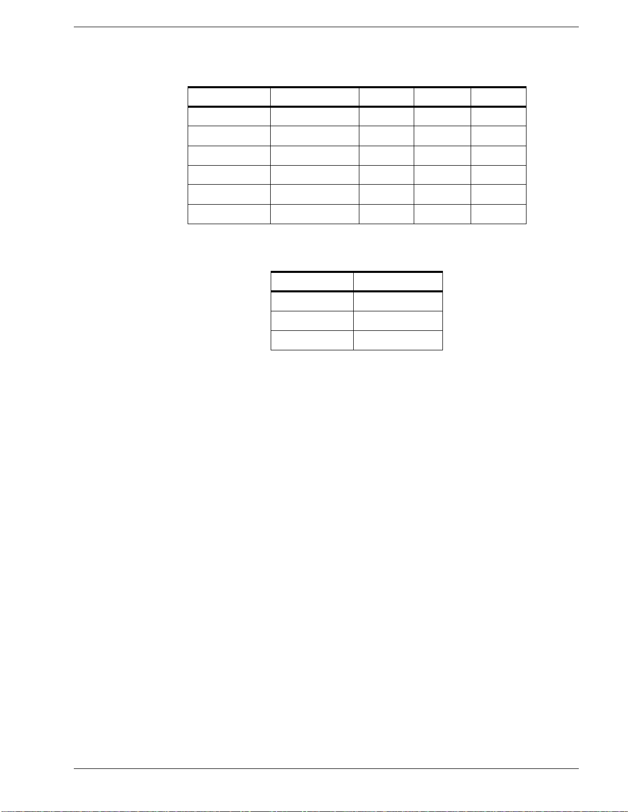
Table 1-3 Data Rate Selection
Table 1-4 Serial Port Pin Assignment
1.10 Limited Warranty
Each new product manufactured by TrueTime is warranted for defects in material or
workmanship for a period of one year from the date of shipment ("Limited Warranty").
Defects in material or workmanship found within that period will be replaced or repaired,
at TrueTime’s option, without charge for material or labor, provided the customer returns
the equipment, freight prepaid, to the TrueTime factory under this limited warranty;
TrueTime will return the repaired equipment, freight prepaid, to the customer’s facility.
This one-year Limited Warranty does not apply to any software or to any product not
manufactured by TrueTime.
If on-site warranty repair or replacement is required, the customer will be charged the
then-current field service rate for portal-to-portal travel time plus actual portal-to-portal
travel charges. There is no charge for on-site warranty repair labor.
Products not manufactured by TrueTime but included as integral parts of a system (e.g.
peripherals, options) are warranted for 90 days or longer, as provided for by the original
manufacturer, from the date of shipment.
Aside from the Limited Warranty set forth above, TrueTime makes no other warranties,
express or implied, of merchantability, fitness for purpose or of any other kind or
description whatsoever.
By purchasing any product manufactured by TrueTime, the buyer consents to and agrees
with TrueTime that as a result of the exclusion of all warranties, expressed or implied, of
merchantability, fitness for purpose, or otherwise, except for the limited one-year
warranty for defects in material and workmanship for products manufactured by
TrueTime, that the Buyer has the sole responsibility to assess and bear all losses relating to
Rate S1-1 S1-2 S1-3 S1-4
9600 off on on off
4800 off off off on
2400 off off on off
1200 on off off on
600 off on off on
300 on off off off
Pin Assignment
2RXD
3TXD
5 Signal Ground

1-14 800TCU User’s Guide 800gench1.fm Rev. A
General Information Limitation Of Liability
(1) the ability of the product or products purchased to pass without objection under the
contract description among merchants and buyers in the trade; (2) the conformity of the
product or products to fair average quality within its contract description; (3) the fitness of
the product for the ordinary purposes for which such product is used; (4) the consistency
of quality and quantity within each unit of product or products and among all units
involved; (5) the adequacy of containers, packaging and labeling of the product or
products; (6) the conformity of the product, promises or affirmations of fact (if any) made
on its label or container; and (7) the conformity of the product to standards of quality
observed by other merchants in the trade with respect to products of similar description.
1.11 Limitation Of Liability
By purchasing any product from TrueTime the Buyer consents to and agrees that the
Buyer’s sole and exclusive remedy for any damages or losses incurred by the Buyer as a
result of TrueTime’s breach of its one-year Limited Warranty for defects in materials and
workmanship or otherwise in connection with any claim respecting the product shall be
limited to the repair or replacement of the product or a refund of the sales price of the
product.
In no event shall the Buyer be entitled to recover consequential damages or any other
damages of any kind or description whatsoever.
1.12 Proprietary Notice
This document, whether patentable or non-patentable subject mater, embodies proprietary
and confidential information and is the exclusive property of TrueTime, Inc. It may not be
reproduced, used, or disclosed to others for any purpose except that for which it is
purchased or loaned.

800gench2.fm Rev. A 800TCU User’s Guide 2-1
2
Installation and Operation
2.1 Introduction
This section contains installation instructions and operating procedures.
2.2 Installation
Unpack the unit and carefully inspect it for shipping damage. Any damage must be
reported to the carrier immediately.
Mount the unit in the desired location in the cabinet; at eye level or below is
recommended.
Connect any required I/O cables to the appropriate input/output connectors. All multi-pin
mating connectors are located in the shipping kit. Connect the AC Input Power cable.
Refer to the name plate on the unit for power specifications.
Only skilled technicians should have access to the contents of this unit.
This unit may contain Custom Options and/or Configurations. If they exist, a
description can be found starting on sheet iii of the index. A specifications or
operational procedure found there supersedes any defined in Sections One or
Two of this manual.
Caution
CAUTION!!! There are extremely dangerous voltages present in this
unit. DO NOT remove the top cover without FIRST disconnecting the
primary power!!!

2-2 800TCU User’s Guide 800gench2.fm Rev. A
Installation and Operation
2.3 General Information and Operation
This section describes operating procedures for the basic unit and many standard options.
The options are noted by a (X) in the Table of Contents. If your particular unit does not
contain one or more of the possible options, disregard references in this section that may
apply to it. In particular, the LCD display has many functions that may be supplied only
with specific options. For example, the LCD can display and be used to change the
Translator input code. If this option is not checked in the Table of Contents, the LCD will
display IRIG-B for the input code and pressing the SETUP key will not initiate the
flashing cursor.
In general, Model 814’s are Generators, Model 820’s are Translators and Model 840’s are
Translator and Generators.
The STOP, START, FWD and REV keys are used to control the unit. The keyboard and
SETUP and ENTER are used to program the unit. The programming operation is
described first followed by descriptions of the control switches.
Press the top of the POWER switch. The numeric display and the alphanumeric display
will go through a turn-on sequence. During the turn-on sequence, the numeric display will
display all eights, the keyboard lamps will all be illuminated and then the numeric display
will display 001 00 00 00. The alphanumeric display will show the program number and
its revision and then display the OPER MODE prompt. If the nonvolatile memory option
is installed, all parameters entered into the unit will be retained when the power is
removed (unless otherwise specified all Model 800 units with multicode options will have
this option installed).
Use the front panel potentiometer to set the viewing angle of the alphanumeric (A/N)
display so that it is easy to read.
Use the number keys to change the prompt on the A/N display. The following list shows
the display versus the key that is pressed. (Note: Some keys are optional).
Key Pressed Displayed Message
•Key #0 -- Operating Mode (GEN//TRANS//SYNC GEN)
•Key #1 -- Time (TRANSLATOR TIME//GENERATOR TIME)
•Key #2 -- OPER STATUS (TRANSLATE//GEN//SYNC-GEN)
•Key #3 -- LEAP YEAR//OSC SELECTION// IEEE-488 ADDRESS
•Key #4 -- ERROR BYPASS//ADV RET RATE
•Key #5 -- EXT START//PROP DELAY//FILTER-POLARITY CONTROL
•Key #6 -- TRANSLATE CODE//GENERATE CODE//SYNC-GEN REF CODE
•Key #7 -- VIDEO MIXER
Keys 8-9 are not used.
Notice that several keys are used for the selection of more than one display. Pressing the
respective key will toggle or scroll the display.

800gench2.fm Rev. A 800TCU User’s Guide 2-3
Installation and Operation
To change a parameter use the SETUP and ENTER keys in conjunction with the number
keys.
If the cursor is flashing and you wish to abort the change mode, press SETUP. The cursor
will stop flashing and pressing a number key will change the prompt not the parameter.
For Models 820 or 840 use the following example to select Positive Polarity mode and
three frames of Error Bypass:
•Press key #4 until the current Error Bypass selection is displayed.
•Press SETUP and the cursor will flash. Sequentially pressing and releasing any
number key will scroll the possible Error Bypass settings through the display. When
3 frames is displayed press ENTER.
•Press key #5 until FILTER CONTROL is displayed. Press SETUP and the display
will read CHANGE FILT CTRL and the current setting will be displayed. Off/On is
the filter status and Inverted/Non-inverted is the polarity setting. Press any number
key and the display will scroll through the four possible settings. When
Off/Non-inverted is displayed, press ENTER.
For Model 814, press START and use the following procedure to select the
Advance/Retard Rate:
•Press key #4 until the current Advance/Retard selection is displayed.
•Press SETUP and the current setting will be displayed and the cursor will be
flashing. Sequentially pressing and releasing any number key will scroll the
possible Advance/Retard selections through the display. When the desired rate is
displayed press ENTER.
Experiment with the keys to get the feel of the options that are supplied and the methods
of changing the various parameters associated with them. Again, if SETUP is pressed and
the flashing cursor does not appear, the displayed parameter is fixed and may not be
changed.
2.4 Detailed Key Information
This section provides details when using the available keys.
Key 0:
Selects the OPERATIONAL MODE display. From this display the Generator,
Synchronized Generator and Translator modes may be selected.
Key 1:
Toggles the alphanumeric display between the GENERATOR TIME and the
TRANSLATOR TIME displays. Pressing SETUP will cause the cursor to flash indicating
that the time may be changed. Use the number keys and the left/right arrow keys to select
the desired time (in the Translator and Sync Gen. modes the preset time will be accepted.
However, it will be corrected to the time contained on the input code).

2-4 800TCU User’s Guide 800gench2.fm Rev. A
Installation and Operation
When the time has been properly entered, press the ENTER key to exit the change
operation.
Key 2:
Selects the OPER STATUS display where various Generator/Translator diagnostic
messages are displayed. The most common message is the Time Valid Code error
display. This appears when input code frames containing errors exceed the number in the
Error Bypass setting, no code is present or it is the wrong format.
Other messages include Gen Stopped, Gen Normal, Trans Stopped, and Osc
Error. In normal operation the display will read Time Valid or Gen Normal.
When the Synchronized Generator mode has been selected, an *is displayed in the
Generator Operational Status display, the unit has calculated the frequency error between
the input code and its time base. If the input code fails, input a correction into the time
base to compensate for the last known frequency error. This compensation will increase
the accuracy of the time base with respect to the input code by approximately one order of
magnitude.
(Note: A unit is programmed to wait for 10 to 15 minutes after power on before the
frequency error is calculated. This allows the internal oscillator to stabilize before
measurements are taken. A w in the display indicates a warm-up period. A cin the
display indicates the calculation period).
Key 3:
Selects either the internal oscillator or the external oscillator as the Generator or Sync
Generator time base. Select the LEAP YEAR function and select the IEEE-488 address.
Press SETUP and ENTER simultaneously while using this key to modify the particular
display that is in view.
1. When OSC SELECTION displays Internal, the Generator or Synchronized
Generator will use the internal time base. When OSC SELECTION displays
External, the Generator or Synchronized Generator will use an external 1 MHz
oscillator provided by the user. (Note that External is selected but no external
oscillator is provided, the OPER STATUS display will read OSC Input Error and
time will not advance).
2. The LEAP YEAR function, when Disabled, will enable the days to be reset to day one
after a count of 365 has been accumulated. When LEAP YEAR is Enabled the days
will be reset to day one after a count of 366 days. Press SETUP and ENTER
simultaneously while number keys to enable or disable the LEAP YEAR as desired.
Leap year is used in the translator mode only. In all other modes the date is used to
determine leap year.
3. Use IEEE-488 ADDRESS to select the address of the IEEE-488 Interface. Press
button number 3 repeatedly until the IEEE-488 ADDRESS prompt shows. Press
SETUP to enter an address which may be any value from 00 to 30. Use the right- or
left-arrow key to position the cursor beneath the digit that you wish to change, then use
the number keys to enter the digit. When the desired address is displayed, press
ENTER. The selected address is saved in non-volatile RAM. Consequently, the
address upon subsequent power-ups will be that used at the previous power-down.

800gench2.fm Rev. A 800TCU User’s Guide 2-5
Installation and Operation
Key 4:
Use to display or modify the Error Bypass or Advance/Retard parameters. Press the
SETUP and ENTER simultaneously and a number key to modify the particular display in
view.
1. ERROR BYPASS is the number of input code frames containing errors that will be
ignored before they are loaded into the internal time registers. From the CHANGE
ERROR BYPASS display, the number keys allow scrolling through the possible
selections on the display. ERROR BYPASS is active in both the Translator and Sync
Generator modes.
2. ADV/RET RATE is used to manually synchronize the Generator to an external
reference. From the CHANGE ADV/RET RATE display, the number keys scroll through
the possible rate selections on the display. The choices can be sequentially made larger
or smaller by pushing the odd or even number keys. The “Disabled”state cancels both
the advance and retard. When the desired rate has been selected, the left- and
right-arrow keys are used to implement the retard and advance each time the
respective key is pressed. When an advance or retard is performed by the internal
logic, the LED above the respective arrow key is momentarily illuminated.
3. In the Synchronized Generator mode, the indicators above the arrow keys are
illuminated when the internal logic automatically performs an advance or retard. The
relative rate of flashing is an indication of the frequency error between the input code
and the Generator time base. If the input code has failed and the *has been
illuminated in the Translator Time Status display, the respective LED above the arrow
keys will flash at the rate at which the automatic 500 ns advance or retard corrections
are being inserted.
Key 5:
Use to select the polarity of the input code, turn the filter on and off, control the Generator
External-Start operation and set the propagation delay.
1. Press key 5 until FILTER CONTROL is displayed. Press SETUP and the display will
read CHANGE FILT CTRL and the current setting will be displayed. Off-On is the
filter status and inverted/non-inverted is the polarity setting. Press any number key and
the display will scroll through the four possible settings. When Off/Non-inverted
is displayed, press ENTER.
2. The EXT START display may be selected by pressing key 5when the unit is in the
Generate mode and is stopped. Pressing SETUP allows the user to select either the
positive or negative going edge of the External Start input pulse, which is used to start
the unit. Press the SETUP and ENTER simultaneously,then any number keys to
select the desired edge, either rising or falling. Pressing the ENTER key will enable
the LED above the START switch, which will flash on the occurrence of each
External Start edge. The flashing LED indicates that the External Start input is active.
The display should read Push Start to engage Ext Start. When the START
switch is pressed, the next edge of the External Start pulse will start the unit.
3. PROPAGATION DELAY is used in the Sync-Generate Mode to compensate for
transmission delays from the source of the input code. Press the SETUP and ENTER

2-6 800TCU User’s Guide 800gench2.fm Rev. A
Installation and Operation
simultaneously and any number keys to select the desired delay.The unit will
synchronize to the input code and the time will be early with respect to the input code
by the amount set into the Propagation Delay.
Key 6:
Selects the GENERATE CODE, TRANSLATE CODE and SYNC GEN REF CODE
displays. Pressing SETUP will cause the cursor to flash indicating that the Code Selection
may be changed. Repeatedly pressing a number key will scroll the possible formats
through the display. Press the ENTER key to save the code selected.
Key 7:
Programmes the various parameters associated with the Video Time Inserter (Mixer)
option.
To program for this option repeatedly press this key to scroll through the possible change
displays, then use the SETUP key to select the desired feature. Use of the ENTER key is
not required. The following list shows each of the possible displays in the order of
appearance with a brief description of each feature.
1. VIDEO PORT SELECT: When the second video port option is installed, this display
provides port selection (1 or 2). The variables described below pertain only to the port
selected.
2. VIDEO MIXER ON-OFF: ON selects the time insertion mode; OFF passes the video
signal through without time information.
3. BACKGROUND OFF-WHITE-BLACK: The time is surrounded by a white, black or
no mask as determined by this parameter.
4. INTENSITY: From this display, the arrow keys are used to increase or decrease the
intensity of the digits.
5. DAYS DIGITS ON-OFF: This display allows the user to either enable or defeat the
three days digits in the inserted time.
6. FRAC SEC: This display enables user to change the resolution or completely cancel
out the insertion of the fractional-seconds time information. The possibilities are:
None, milliseconds resolution, hundredths-of-seconds resolution and
tenths-of-seconds resolution.
7. HORIZ POSITION: Pressing the left and right arrow keys will move the horizontal
position of the inserted time.
8. VERT POSITION: Pressing the left and right arrow keys will move the vertical
position of the inserted time.
9. HORIZ CHAR SIZE: Pressing the left and right arrows will increase and decrease the
horizontal size of the inserted characters. Use this display in conjunction with the
VERT CHAR SIZE to achieve the desired aspect ratio.
10. VERT CHAR SIZE: Pressing the left and right arrows will increase and decrease the
vertical size of the inserted characters.
FWD is used to start the Translator in the forward direction. The FWD indicator will be
illuminated when the unit is in the forward mode. Pressing STOP will halt the Translator.
Table of contents


