Mastech MS6100 User manual

MULTI-FUNCTION DIGITAL COUNTER
Multi-Function Digital Counter
kHz
MHz
uS
100M
10M
OFL
B INPUT
100MHz-1.3GHz
3V MAX
50
A INPUT
10Hz-100MHz
250V MAX
1M
35PF
RESET
HOLD CHECK A.TOT A.PERI x1/x20
G.TIME FREQ. OUT/IN
FUNCTION SELECTDISPLAY
OFF
ON
A.ATTN L.F
MAX 1300MHz
1300M
GATE
CAT III
300 V

Multi-Function Digital Counter Multi-Function Digital Counter
Introduction
This manual contains information and warnings, which must be followed to ensure safe operation and retain the instrument in safe
condition.
READ “ SAFETY INFORMATION ” BEFORE USING THE INSTRUMENT
This is an intelligent multiple function digital counter. It is controlled by an 8-Bit micro-controller and with eight-digit
LED high bright display. Four measuring functions of frequency, period, totals and self-check are involved in this
counter. Otherwise there is a 10MHz OSC.OUT. The input signal can be conditioned by attenuation.
Two kinds of power 110VAC and 220VAC can be supplied to the instrument. User can conveniently select it. This
instrument has been designed according to IEC1010 – 1 concerning safety requirements.
Unpacking and Inspection
Upon removing your new instrument from its packing, you should have the following items:
1. Multiple function digital counter.
2. BNC to BNC Test Lead, 50 ohm, 100cm
3. Power Cord
4. Users Manual
If any of the above items are missing or are received in a damaged condition, please contact the distributor from whom you
purchased the unit.
Safety Precautions
Injury or death can occur even with low voltages and low current. It is extremely important that you read these safety informations
before using your instrument. Follow all safety practices and proper operating procedures for equipment being tested.
1. Exercise extreme caution when: Measuring voltage above 20 volts, measuring current greater that 10 mA, measuring AC power
line with inductive loads, measuring AC power line during electrical storms.
2. Always inspect your instrument, test lead and accessories for sign of damage or abnormality before every use. If any abnormal
conditions exist (i.e., broken or damaged test lead, cracked case, display not reading, etc.), do not attempt to take measurements.
3. Never ground yourself when taking electrical measurements. Do not touch exposed metal pipes, which might be at ground
potential. Keep your body isolated from ground by using dry clothing; rubber shoes, rubber mats, or any approved insulating
material.
4. Never touch exposed wiring, connections, test probe tips, or any live circuit conductors when attempting to make measurements.
INTRODUCTION
UNPACKING AND INSPECTION
SAFETY PRECAUTIONS
SAFETY INFORMATION
SYMBOL EXPLANATION
INSTRUMENT FORWARD LAYOUT
INSTRUMENT REAR LAYOUT
INTRODUCTION
FREQUENCY MEASUREMENT
PERIOD MEASUREMENT
TOTAL MEASUREMENT
CHECK MODE
GENERAL SPECIFICATIONS
RESOLUTION AND ACCURACY
INPUT CHARACTERISTICS
GENERAL MAINTENANCE
REPLACING THE POWER FUSE
OTHER NOTE
1
1
1
2
2
3
7
8
9
9
9
9
10
10
11
11
12
12

5. Never replace the protective fuse inside the instrument with a fuse other than the specified or approved equal fuse. Replace only
with same type of fuses. To avoid electrical shock, disconnect the Power Cord, test lead and any input signals before replacing
the fuses.
6. Do not operate this instrument in an explosive atmosphere (i.e., in the presence of flammable gases or fumes, vapor or dust.)
7. Measuring voltage that exceeds the limits of the instrument may damage it and expose the operator to a shock hazard. Always
recognize the instrument voltage limits as stated on the front of the instrument.
8. Never apply more than 250V between the A input and earth ground. Never apply more than 3V between the B input and earth
ground.
9. Do not attempt calibration or service unless trained and another person capable of rendering first aid and resuscitation is present.
10.Remember: Think Safety, Act Safely.
Safety Information
This product complies with the requirements of the following European Community Directives: 89/336/EEC (Electromagnetic
Compatibility) and 73/23/EEC (Low Voltage) as amended by 93/68/EEC (CE Marking).
Symbol Explanation
Note-Important safety information, refer to the instruction manual.
Earth (ground) TERMINAL
Caution, possibility of electric shock
Equipment protected throughout by double insulation or reinforced insulation.
Direct current
Alternating current
CAT III: MEASUREMENT CATEGORY III is applicable to test and measuring circuits connected to the distribution part of the building's
low-voltage MAINS installation.
Instrument forward Layout
1 2 3 4 5 6 7 8 9 10 11
12
13
kHz
MHz
uS
100M
10M
OFL
B INPUT
100MHz-1.3GHz
3V MAX
50
A INPUT
10Hz-100MHz
250V MAX
1M
35PF
RESET
HOLD CHECK A.TOT A.PERI x1/x20
G.TIME FREQ. OUT/IN
FUNCTION SELECTDISPLAY
OFF
ON
A.ATTN L.F
MAX 1300MHz
1300M
GATE
Multi-Function Digital Counter Multi-Function Digital Counter
03
Multi-Function Digital Counter

04
1. Power Switch
To turn on, depress push button. To turn off, again depress push button.
2. Hold
Depress HOLD button to toggle in and out of the Data Hold mode. Releasing Data Hold mode again press the button.
3. RESET
Pressing RESET, immediately eight-digit LED and eight LED indicators of the instrument are full lit. After RESET, the instrument is
auto 10Mz frequency measurement range.
4. CHECK
Pressing the CHECK button, eight-digit LED and eight LED indicators are lit from 0 to 9 to eight LED indicators. So circle.
5. A.TOT
Pressing A.TOT button to Total measurement mode.
6. A.PERI
Pressing A.PERI button to period measurement mode.
7. G.TIME
For frequency measurement mode, this button is used to change gate time. When period measurement mode, this button is used
to change the multiplier factors. Each range is as follows:
Channel a input mode
Frequency resolution
Gate Time 10MHz Range Resolution 100MHz Range Resolution
0.02 Ses 00000.0kHz 000.000kHz
0.2 Ses
2 Ses
00000.00kHz
00000.000kHz
000.0000kHz
000.00000kHz
Gate Time Resolution
0.02 Ses 0.0μs
0.2 Ses
2 Ses
0.00μs
0.000μs
Period resolution
Channel b input mode
Frequency resolution
Gate Time 1300MHz Range Resolution
0.025 Ses 0000.00kHz
0.25 Ses
2.5 Ses
0000.000kHz
0000.0000kHz
Multi-Function Digital Counter Multi-Function Digital Counter
05

8. FREQ.
For frequency measurement mode, this button is used to change frequency range. After RESET, The instrument is auto into
10MHz-frequency measurement range. This button is pushed one time; instrument is auto into 100MHz-frequency measurement
range. This button is pushed one time again; instrument is auto into 1300MHz-frequency measurement range. So circle.
9. A.ATTN
Input signal attenuate button. When depress, the sensitivity is attenuated by a factor 20 for input signal.
10. L.F
Low pass filter button. When depress:
~100kHz, -3dB
~150kHz, -3dB at ATTN condition
11. A INPUT
Channel A input BNC connector.
Put a signal in to measure for 10 Hz ~100MHz frequency, period and total.
12. B INPUT
Channel B input BNC connector.
Put a signal in to measure for 100M Hz ~1300MHz frequency.
13. DISPLAY
EIGHT-DIGIT LED: Display measurement value.
GATE INDICATOR: Display the opened or closed state of the GATE. When GATE is open, indicator is lit.
OFL INDICATOR: When overflow, the indicator is lit.
1300MHz INDICATOR: When selecting the 1300MHz range, the indicator is lit.
100MHz INDICATOR: When selecting the 100MHz range, the indicator is lit.
10MHz INDICATOR: When selecting the 10MHz range, the indicator is lit.
kHz INDICATOR: The unit of frequency.
MHz INDICATOR: The unit of frequency.
μS INDICATOR: The unit of period.
Instrument Rear Layout
1 3 42
CAUTION
CONNECTED TO GROUND.
WITH SPECIFIED TYPE AND RATED FUSE.
FUSE. FOR FIRE PROTECTION REPLACE ONLY WITH
DISCONNECT INPUT POWER BEFORE REPLACING
PROTECTION GROUNDING CONDUCTOR MUST BE
TO AVOID ELECTRIC SHOCK, THE POWER CORD
50/60Hz
OSC.OUT
POWER SELECT
220
FUSE: F200mA/250V, 5X20mm
POWER INPUT
MAX 20VA
CAUTION
90~132V
50/60Hz
198~264V
50/60Hz
AC AC
(10MHz)
GROUND
SERIES NO.
PLEASE READ MANUAL FOR SAFETY
Multi-Function Digital Counter Multi-Function Digital Counter
07

08
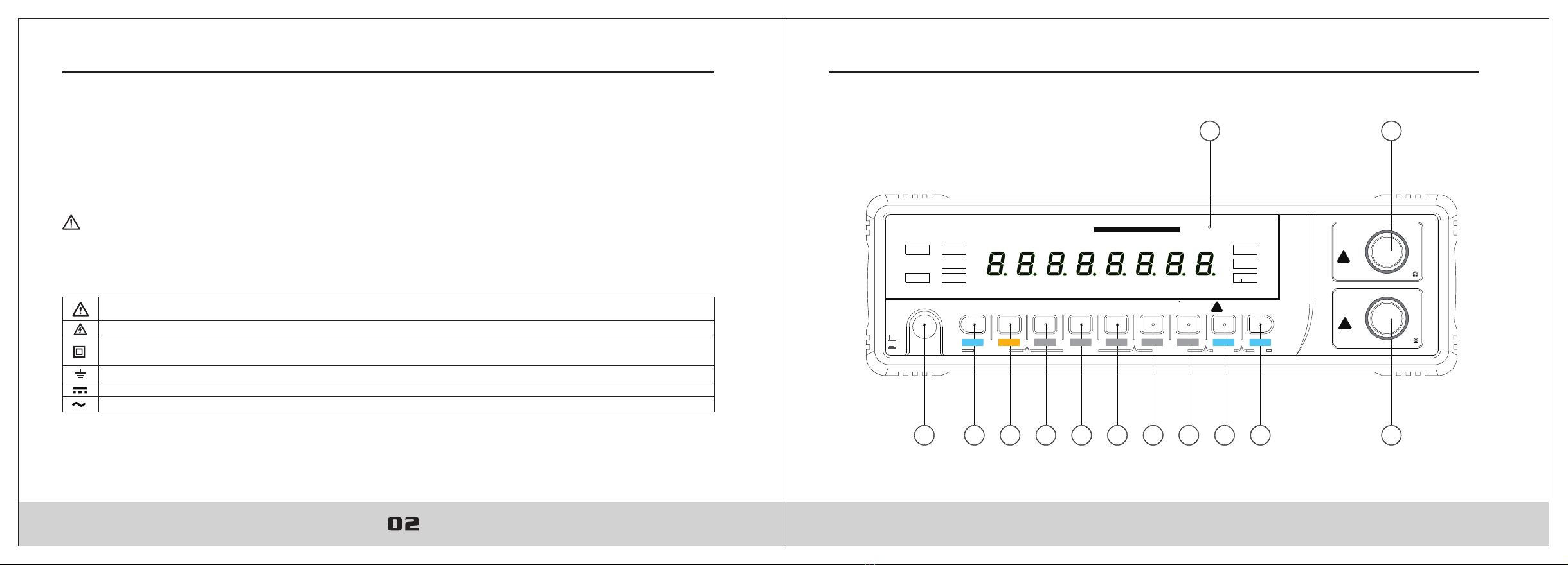
1. POWER INPUT WITH FUSE
To avoid user for injury and the instrument for damage, the voltage value of AC power must be examined
with same the power requirements of instrument before connect power cord to live power source and the
power select switch is turned on.
To avoid electrical shock, disconnect power cord from live power source and remove the test leads and any
input signals before replacing the power fuses. Replace only with the same type of fuses.
2. POWER SELECT
Two kinds of power 110VAC and 220VAC can be supplied to the instrument. According to the user’s needs, select it.
3. OSC.OUT
Output connector for reference oscillator. This connector provides a 10MHz signal. It may be used as used as a reference signal
for other frequency counter. When the output signal (10 MHz) is used, is always terminated by 50ohms.
4. GND TERMINAL
To avoid user for injury and the instrument for damage, the voltage value of AC power must be examined
with same the power requirements of instrument before connect power cord to live power source and the
switch is turned on.
Introduction
Before making any measurements always examine the instrument and accessories used with the instrument for damage,
contamination (excessive dirt, grease, ect.) and defects. Examine the test leads for cracked or frayed insulation and make sure the
lead plugs fit snugly into the instrument jacks. If any abnormal exist do not attempt to make any measurements.
Frequency Measurement
• Press the POWER button to the ON position.
• Press the FREQ. button to select the appropriate range that you are desirous to.
• Press the G. TIME button to select the desired gate time.
• Connect the input signal to the front –panel BNC connector.
• Set A.ATTN. to desired position. If input signal level is greater than 300mV, depress the A.ATTN. button to decrease the triggering
sensitivity of the input section by a 20 and reduce errors.
• Read the frequency on display, and observe the unit of measurement indication.
Period Measurement
• Press the POWER button to the ON position.
• Press the A.PERI. button to select the period mode.
• Press the G. TIME button to select the desired gate time.
• Connect the input signal to the A INPUT BNC connector.
• If input signal level is greater set A.ATTN. button to decrease the triggering sensitivity of the input section by a 20 and reduce errors.
• Read the period time on display, and observe the unit of measurement indication.
Total Measurement
• Press the POWER button to the ON position.
• Press the A.TOT. button to select the total mode.
• Connect the input signal to the A INPUT BNC connector.
• If input signal level is greater, set A. ATTN. button to decrease the triggering sensitivity of the input section by a 20 and reduce errors.
• Read the accumulated total on display after HOLD button in.
Check mode
• The self – check mode provides a means of verifying proper overall operation of counter, excluding input section, time base
accuracy, and time base dividers used in the period mode.
• Press the POWER button to the ON position.
• Press the CHECK button to select the self – check mode.
• Eight-digit LED and eight LED indicators are lit from 0 to 9 to eight LED indicators. So circle.
• Press RESET button to stop the check.
Multi-Function Digital Counter Multi-Function Digital Counter
09

10
General Specifications
Display: 8 digit, about 10mm high red LED display with decimal point.
Overrange indications: OFL indication is lit.
Power Requirement: AC198~264V 50/60Hz or 90~132V 50/60Hz
Temperature: Operating 0°C to 40°C
Storage -10°C to 50°C
Relative Humidity: 20% to 80% RH (0°C to 40°C)
Safety: Designed to IEC 1010-1 standard
Size: 300mm (L)x260mm (W)x74mm (H)
Weight: Approx. 1850g.
Frequency measurement: ±1 count ± time base error x frequency
Period measurement: ±1 count ± time base error x period
Time base error: Long term stability 1x10 (month)
Short term stability 5x10 (minute)
Accuracy is given as at 18°C to 28°C, with relative humidity up to 80%. All specifications assume less than 1 year since calibration.
-5
-6
Resolution and Accuracy
Frequency measurements
Channel Range Resolution
A10MHz 10Hz to 10MHz 1, 10, 100Hz selectable
B
100MHz 10MHz to 100MHz
1300MHz 100MHz to 1300MHz
10, 100, 1000Hz selectable
100, 1000Hz, 10kHz selectable
Accuracy
±1 count ± 1x10 x frequency (month)
±1 count ± 5x10 x frequency (minute)
-5
-6
Channel Range Resolution
A
(only)
0.1s to 0.1μs
(10Hz to 10MHz)
±1 count ± 1x10 period (month)
Accuracy
Period measurements
Multi-Function Digital Counter Multi-Function Digital Counter
-5
±1 count ± 5x10 period (minute)
-6
0.0μs, 0.00μs
0.000μs selectable
Channel Range Resolution
A (only) 10Hz to 10MHz
Total measurements
1 count input
Input Characteristics
Channel A
Input voltage sensitivity:
10MHz range: 10Hz to 8MHz 25mV rms. 8MHz to 10MHz 50mV rms.
100MHz range: 10MHz to 80MHz 25mV rms. 80MHz to 100MHz 50mV rms.
Attenuation: x1, x20 fixed
Impedance: approx. 1MΩ less than 35pF
Maximum voltage protection: 250V RMS
Channel B
Input voltage sensitivity: 20mV rms.
Impedance: approx. 50Ω
Maximum input voltage: 3V RMS
General Maintenance
Periodically wipe the case with a damp cloth and mild detergent. Do not use abrasives or solvents.
Dirt or moisture in the terminals can affect readings.
To clean the terminals:
1.Press the power button to OFF.
2.Remove the power Cord from live power source.
3.Remove the test leads from the input terminals.
4.Shake out any dirt that may be in the terminals.
To avoid electrical shock, disconnect power cord from live power source and remove the test leads and
any input signals before replacing the power fuses. Replace only with same type of fuses.
11

Replacing the Power Fuse
Use the following procedure to examine or replace the power fuses:
1.Press the power button to OFF.
2.Remove the power cord from live power source.
3. Remove the test leads from the input terminals.
4. Replace the power fuse from the supply power Inlet with fuse. Replace the blown fuse with same ratings.
5. The power fuse: Fast, F 200mA H 250V,Ø5×20mm.
Other Note
1. Do not use abrasives or solvents on the instrument, use a damp cloth and mild detergent only.
2. If any faults or abnormalities are observed, the instrument can not be used any more and it has to be checked out.
Multi-Function Digital Counter
R-00-05-0088
12
Table of contents
Popular Cash Counter manuals by other brands

Hickok
Hickok 380 Series instruction manual

Garland
Garland ED Series Installation & operation manual

Suzohapp
Suzohapp CUBE HOPPER MKII Instruction and service manual

ipf electronic
ipf electronic VY200120 quick start guide

Cashmaster
Cashmaster Omega 230 user manual

DEUTA Controls
DEUTA Controls enocean AL-436-00-921 manual

Kübler
Kübler CODIX 521 operating instructions

Simex
Simex SLE-73 user manual

Velleman
Velleman CDET1 user manual

Leader Electronics Corp.
Leader Electronics Corp. LDC-824 instruction manual

V-Count
V-Count Ultima AI Installation and configuration

Diamond Traffic Products
Diamond Traffic Products Phoenix instruction manual