Fluke 8024B User manual

NOTE
This manual documents the Model 8024B and its assemblies at the revision levels
shown in Appendix A. If your instrument contains assemblies with different revision
letters, it will be necessary for you to either update or backdate this manual. Refer to
the supplemental change/errata sheet for newer assemblies, or the backdating sheet
in Appendix Afor older assemblies.
Digital
Multimeter
Instruction Manua
P/N 616052
July 1981
Rev. 15/82
©1982, John Fluke Mfg. Co., all rights reserved. Litho in U.^.A.

Dear Customer:
Congratulations! We at Fluke are proud to presentyou with theModel8024B
Multimeter. This instrument represents the very latest in integrated circuit and
display technology. As aresult, the end product is arugged and reliable
instrument whose performance and design exhibit the qualities of afinely
engineered lab instrument. SECTION TITLE PAGE
To fully appreciate and protect your investment, we suggest you take afew
moments to read the manual. As always, Fluke stands behindyour 8024B with a
full 2-year warranty and aworldwide sendee organization. If the need arises,
please don ’t hesitate to call on us.
Thank you for your trust and confidence.
John Fluke Mfg. Co., Inc.
i
2
INTRODUCTION AND SPECIFICATIONS .. . 1-1
1-1. INTRODUCTION !-!
1-3. SPECIFICATIONS 1-1
OPERATING INSTRUCTIONS 2-1
2-1. INTRODUCTION 2-1
2-3. PREPARING FOR OPERATION 2-1
2-4. Unpacking 2-1
2-7. Battery or Fuse Installation/ Replacement 2-i
2-9. PHYSICAL FEATURES 2-3
2-1 1. OPERATING NOTES 2-6
2-13. Input Overload Protection 2-6
2-15. Input Connection to COMMON 2-6
2-17. Fuse Check 2-7
2-19. Fuse Replacement 2-7
2-21. The Display 2-8
2-26. OPERATION 2-9
2-28. AC/DC Volts (V) Operation 2-9
2-30. AC/ DC Current (mA) Operation 2-9
2-32. Resistance (£2) Operation 2-9
2-34. Continuity Testing 2-13
2-36. Diode Testing 2-13
2-38. Conductance (S) Operation 2-13
2-40. Temperature (°C) Operation 2-13
2-43. Level Detector Operation .i2-16
2-45. Peak Hold Operation 2-17
2-47. INITIAL CHECK-OUT PROCEDURE 2-19
2-49. MEASUREMENT TECHNIQUES 2-21
2-51. Temperature Conversion 2-21
2-53. Conductance-to-Resistance Conversion 2-24
2-55. AC Measurements 2-24
2-57. AC/ DC/ Voltage Measurements 2-24
2-60. AC/ DC Current Measurements ^2-24
i(continued on page ii)

8024
B
8024 B
TABLE OF CONTENTS, continued
SECTION TITLE PAGE
2-64. Resistance Measurements 2-27
2-67. APPLICATIONS 2-29
2-69. THERMOCOUPLES 2-29
2-70. Introduction 2-29
2-73. Monitoring More Than One Thermocouple 2-3!
2-
75. Leakage Tester 2-31
3THEORY OF OPERATION 4-1
3-
1. INTRODUCTION 3-1
3-3. OVERALL FUNCTIONAL DESCRIPTION 3-1
3-5. A/D Converter 3-1
3-14. Voltage Measurement Function 3-6
3-16. Current Measurement Function 3-6
3-18. Temperature (°C) Measurement Function 3-6
3-20. Resistance Measurement Function 3-6
3-23. Conductance Measurement Function 3-3 1
3-25. Peak Hold Circuit Level ;3-11
3-
27. Level Detector Circuit 3-11
4MAINTENANCE., 3-1
4-
1. INTRODUCTION.... .....' 4-1
4-3. SERVICE INFORMATION 4-1
4-7. GENERAL INFORMATION 4-3
4-8. Access Information 4-3
4-17. Cleaning 4-5
4-19. Battery/ Backup Fuse Replacement 4-6
4-21. PERFORMANCE TEST 4-6
4-23. Initial Procedure 4-6
4-25. Display Test 4-7
4-27. Voltage Test 4-8
4-29. Current Test 4-8
4-3 1.Resistance/ Conductance Test 4-8
4-33. Peak Hold Test 4-1
1
4-35. Continuity Test 4-11
4-37. Level Detector Test 4-12
4-39. BT Test 4-12
4-41, Temperature Test 4-14
4-43. CALIBRATION ADJUSTMENTS 4-14
4-
46. TROUBLESHOOTING 4-15
5LIST OF REPLACEABLE PARTS 5-1
5-
1. INTRODUCTION 5-1
5-4. HOW TO OBTAIN PARTS 5-2
TABLE OF CONTENTS, continued
SECTION TITLE PAGE
6ACCESSORIES INFORMATION 6-1
|6-1. INTRODUCTION 6-1
J; 6-3. DELUXE CARRYING CASE (C90) 6-1 '
l6-5. RUGGED CARRYING CASE (Y8I05) ....! \6-1.
|6-7. TYPE KSHEATHED THERMOCOUPLE (Y8102) ... 6-1
6-8. Introduction 6-i
6-10. Specifications 6-4
|6-11. TYPE KBEAD THERMOCOUPLE (Y8103) 6-4
6-12. Introduction 6-4
6-14. Specifications 6-4
6-15. THERMOCOUPLE TERMINATION (Y8I04) 6-4
l6-17. TEMPERATURE PROBES (80T-150C and 80T-150F) .6-5
f; 6-18. Introduction 6-5
i6-20. Specifications 6-5
6-21. HIGH VOLTAGE PROBE (80K-6) 6-5
f- 6-22, Introduction -6-5
6-24. Specifications _6-5
6-25. HIGH VOLTAGE PROBE (80K-40) 6-5
6-26. Introduction 6-5
6-28. Specifications 6-6
6-29. HIGH FREQUENCY PROBE (83RF) 6-6
6-30. Introduction -6-6
6-32. Specifications 6-6
6-33. HIGH FREQUENCY PROBE (85RF) 6-6
j6-34. Introduction 6-6
6-36. Specifications •6-7
6-37. CURRENT TRANSFORMER (801-600) 6-7
h: 6-38. Introduction 6-7
6-40. Specifications 6-7
6-41. CURRENT SHUNT (80J-IO) •6-7
6-42. Introduction 6-7
6-44. Specifications 6-7
6-45. BATTERY ELIMINATOR (A8I) 6-8
6-47. AC/ DC CURRENT PROBE (YRI0O) 6-8
i6-48. introduction 6-8
;6-50. Specifications 6-8
|6-51. AC CURRENT TRANSFORMER (Y8 101) 6-9
6-52. Introduction 6-9
|6-54. Specifications 6-9
j6-55. SAFETY DESIGNED TEST LEAD SET (Y8I32) 6-9
6-57. DELUXE TEST LEAD SET (Y8I34) 6-10
:6-59. SUM FLEX TEST LEAD SET <Y8 140) 6-10
7SCHEMATIC DIAGRAMS -7-1
AMANUAL CHANGE AND BACKDATING INFORMATION A-1
(continued on page Hi)

8024B
8024B
List of Tables
TABLE TITLE PAGE
1-2
1-3
2-1. 2-4
2-7
2-2.
2-3.
2-4.
4-1.
2-22
.2-29
Test Equipment Required 4-2
4-7
4-9
4-10
4-11
4-17
5-3
5-6
5-8
5-12
5-5. Federal Supply Codes for Manufacturers. -5-15
IV
List of Illustrations
FIGURE TITLE PAGE
2-1. Removing the Battery Cover 2-2
2-2. Battery Removal 2-3
2-3. Controls, Indicators, and Connectors 2-4
2-4. Display... -2-8
2-5. Abnormal Status Indicators 2-9
2-6. Volts Operation 2-10
2-7. Current Operation 2-11
2-8. Resistance Operation 2-12
2-9. Conductance Operation 2-14
2-10. Temperature Operation 2-15
2-11. Level Detector Operation •2-17
2-12. Peak Hold Operation 2-18
2-13. Temperature Correction Factor For K-Type
Thermocouples 2-21
2-14. Conductance-to-Rcsistancc Conversion 2-25
2-15. Waveform Conversion —2-26
2-16. Voltage Measurement Error Calculations 2-27
2-17. Current Measurement Calculations 2-28
2-18. Thermocouples. 2-30
2-19. Thermocouple Termination Unit 2-32
2-
20. Multipoint Selection 2-32
3-
1.8024BBlock Diagram -3-2
3-2. A/ DConverter Functional Diagram 3-4
3-3. Integrate Capacitor Waveform •3-5
3-4. Voltage Measurement 3-7
3-5. Current Measurement 3-8
3-6. Temperature Measurement 3-9
3-7. Resistance/ Conductance Measurement 3-10
3-8. Simplified Peak Hold Circuit 3-12
3-
9. Simplified Level Detector Circuit 3-13
4-
1. Calibration Adjustments Location 4-3
4-2. LCD Display Assembly 4-5
v-(continued on page viii)

8024B
LIST OF ILLUSTRATIONS, continued
FIGURE TITLE PAGE
4-3. General Equipment Connection 4-7
4-4. General Equipment Connection —Current 4-10
4-5. BT Test 4-13
4-
6. Lag Bath 4-16
5-
1. 8024B Final Assembly 5-4
5-2. A1 Case Assembly 5-7
5-3. A2 Main PCB Assembly ..5-1
1
5-
4. A3 Switch PCB Assembly 5-12
6-
1. 8024B Accessories 6-2
vt
8024B
Section 1
1-1. INTRODUCTION
ft 1-2. Your John Fluke Model 8024B is apocket-size digital multimeter that is ideally
|i suited for application in the field, laboratory, shop, or home. Some of the features of your
instrument are:
ft FUNCTIONS: All standard VOM measurement functions -- ac/dc voltage, ac/dc
/current, resistance —plus:
§•' Conductance: Anew multimeter function that allows fast, accurate, noise-free
M- resistance measurements up to 10.000 Mil.
HTemperature: Used with aK-type thermocouple, this function provides direct
|| display in degrees Celsius for K-type thermocouples.
|£ Peak-Hold: Provides short-term memory for capturing the peak value of
ft transient ac or dc signals such as motor starting current.
|| Continuity: Provides an immediate visual and audible indication when
§i continuity is detected (use for passive circuit testing).
Level Detector: Senses logic levels and other active signals less than 250V dc or ac
rms. Visual and audible indications of the results are provided.
it RANGE for each function has: )
fFull autopolarity
Overrange indication
fEffective protection from overloads
vDual slope integration measurement technique to ensure noise-free measurements
1-1

8024B 802.4B
OPERATOR CONVENIENCE:
3I/2-digit liquid crystal display: Ahigh contrast display that can be easily read
from across the room. No more worries about bent needles, parallax, etc.
Long term calibration stability: 2years. Easy calibration -few adjustments.
Lightweight: .482 kg(!7 ounces).
Safety Designed Test Leads: Finger guards on the probe and shrouded contacts on
connectors reduce the chance of accidental contact with circuit voltages.
POWER:
Up to 100 hours of continuous operation can be expected from asingle,
inexpensive, 9-volt, alkaline battery (transistor radio/calculator type).
Low battery voltage is automatically detected and displayed. The low battery-
indication, BT, appears in the display when about 10 hours of operation remain.
Line operation is possible using aModel A81 Battery Eliminator. (See Section 6.)
ACCESSORIES:
Afull line of accessories are available to extend the range and scope of your
instrument. They are listed in Table 1-1 and described in detail in Section 6.
1-3. SPECIFICATIONS
1-4. Table 1-2 lists the specifications of your 8024B.
Table 1-1. 8024B Accessories
MODEL NO. DESCRIPTION
C90 Deluxe Carrying Case (Soft Vinyl)
Y8105 Rugged Carrying Case (Molded Plastic)
Y8102 Type KSheathed Thermocouple
Y8103 Type K Beaded Wire Thermocouple
Y8104 Thermocouple Termination Kit
80T-150C Temperature Probe °C
80T-150F Temperature Probe °F
80K-6 High Voltage Probe
80K-40 High Voltage Probe
83RF High Frequency Probe
85RF High Frequency Probe
Table 1-1. 8024B Accessories (cont)
MODEL NO. DESCRIPTION
801-600 Current Transformer, 2" jaw opening
80J-10 Current Shunt
A81 Battery Eliminator
Y8100 AC/DC Current Probe
Y8101 Current Transformer 7/16” jaw opening
Y8132 Safety Designed Test Lead Set
Y8134 Deluxe Test Lead Set
Y8140 Slim Flex Test Lead Set
Table 1-2. 8024B Specifications
The following electrical specifications assume a2-year calibration cycle and
an operating temperature of 18° Cto 28° C(64° Fto 82° F) at relative humidity
up to 90% unless otherwise noted.
FUNCTIONS: DC Volts, AC Volts, DC Current, AC Current, Resistance, Diode
Test, Conductance, Temperature, Peak-Hold, Continuity, and Level Detection.
DC VOLTS
RANGE RESOLUTION ACCURACY FOR 2YEARS
+200 mV 100 MV
±2V 1mV
±20V 10 mV .. +(0.1% of reading +1digit)
±200V 100 mV
±1 ooov IV
Response Time Less than 1sec.
Overvoltage Protection 1000V dc or peak ac on all ranges, except
200 mv (15 sec max above 300V dc or rms)
Input impedance 10 MO, all ranges
Normal Mode Rejection Ratio >-60 dB at 50 Hz and 60 Hz
Common Mode Rejection
Ratio (1 kO unbalance) >100 dB at dc, 50Hz and 60 Hz
1-2 1-3

8024B
Table 1-2. 8024B Specifications (cont)
AC VOLTS {Average Sensing, RMS Calibrated Sinewave):
RANGE RESOLUTION
200 mV 100 MV
2V1mV
20V 10 mV
200V 0.1V
750V IV
ACCURACY
45 Hz to 1kHz 1kHz to 2kHz 2kHz to 5kHz
±(0.75%
of reading
+2 digits)
±{1.5% of
reading +3
digits)
+(5% of
reading
+5 digits)
Not
Specified
+{1%of '
reading +2
digits)
No?
Specified
Response Time Less than 2seconds
Overload Protection 750V rms or 1000V peak continuous, except
200 mV ac ranges {15 seconds maximum
above 300V rms).
Common Mode Rejection
Ratio {1 kSl unbalance) >60 dB at 50 Hz and 60 Hz
Volt-Hz Product 107max (200V at 50 kHz)
Input Impedance 10 M£2 in parallel with <100 pF
DC CURRENT
RANGE RESOLUTION ACCURACY
FOR 2YEARS BURDEN
VOLTAGE
2mA 1MA
+(0.75% of
reading +1
digit)
0.3V max
IIP 10 fi A
M100 /U A
2000 mA 1mA 0.9V max
Response Time Less than.-l second
Overload Protection 2A/250V fuse in series with 3A/600V fuse.
Response Time Less than.-l second
Overload Protection 2A/250V fuse in series with 3A/600V fuse.
1-4
8024B
Table 1-2. 8024B Specifications (cont)
AC CURRENT
RANGE RESOLUTION
ACCURACY for 2Years BURDEN
VOLTAGE
45 Hz to
450 Hz 450 Hz to
1kHz
2mA 1jXA ±(3% of
reading
±2 digits)
Not
Specified
0.3V rms
20 mA 10 JUA.
+(1.5% of reading +2 ,
digits)
200 mA 100 flA 0.9V rms
max
2000 mA 1mA
Response Time Less than 2seconds
Overload Protection 2A/250V fuse in series with 3A/600V fuse.
Response Time Less than 2seconds
Overload Protection 2A/250V fuse in series with 3A/600V fuse.
RESISTANCERESISTANCE
RANGE RESOLUTION ACCURACY
FOR 2YEARS FULL-SCALE
VOLTAGE
MAXIMUM
TEST
CURRENT
200£2 o.i£2 ±(0.2% Of
reading +3 digits) <0.25V .35 mA
2k!2-H- i£2 ±(0.1% of 1.1 mA
20 k£2 io£2 reading +1
digit) 13 jUA
200 k£2 ioo£2 13 /lA
2000 k£2 1k£2 0.13 /i A
20 M£2 io k£2 +(2% of
reading +1 digit) >.7V 0.13 ft A
Overload Protection 500V dc/ac rms on all ranges (15 sec max
above 300V dc or rms ac)
Overload Protection 500V dc/ac rms on all ranges (15 sec max
above 300V dc or rms ac)
Open Circuit Voltage Less than ,1.5V on ail ranges except 2k£2
range is less than 3.5V.
Diode Test The three ranges—2k£2, 200 k£2, 20 Mo-
have endugh open circuit voltage to turn on
silicon junctions allowing adiode test. The
2kO range is preferred and is marked with a
diode symbol. The three non-diode test
ranges —200 £2, 20 k£2, and 2000 k£2 ••-•-will
not turn on silicon junctions when making
in-circuit resistance measurements.
T-5

8024B
Table 1-2. 8024B Specifications (cont)
CONDUCTANCE*
Range 200 nS
Equivalent Resistance
Range 5MOto 10,000
Accuracy +(2.0% of reading +10 digits)
Resolution... 0.05% of range (1 0‘10 S)
Overload Protection 500V dc/rms ac (1 5sec max above 300V dc
or rms ac)
Diode Test Will forward bias a typical PN junction
'Conductance is the inverse of ohms (I/O) and is expressed in siemens (S).
Adecrease in conductance is equivalent to an increase in resistance.
PEAK HOLD Use for Measuring Transient Signals
FUNCTIONS, RANGES AC or DC, VOLTS or CURRENT
ALL RANGES
AC
Accuracy
(48 —450 Hz)
3% of reading +10 digits, all ranges
(except 2mA, 6% of reading +10 digits).
Average sensing, calibrated to read
highest rms value of sine wave.
Acquisition Time 150 ms"
DC
Accuracy 3% of reading +10 digits, positive pulses
Acquisition Time 10 ms** square pulse
(3 ms square or 8ms half sine typ.)
Display Decay Rate <1 digit/sec
"Acquisition Time is the minimum duration of peak or surge for rated
accuracy.
Accuracy improves for longer peak duration.
TEMPERATURE (Thermocouple accessory required)
Temperature Sensor K-Tvpe Thermocouple (Chromel-Alume!)
See accessories
Range -20° Cto +1265° C
Resolution
1-6
8024B
Table 1-2. 8024B Specifications (cont)
Accuracy
±3° C±1 digit, -20° to +300° C
3% of reading, +300° Cto +1265°C
(Accuracy includes NBS conformity,
calibration stability, zero, and reference
junction but not thermocouple errors.)
Connection
Dual banana isothermal termination pro-
vided with FLUKE thermocouple acces-
sories. Use Y8104 termination accessory
for any K-Type thermocouple.
Overload Protection 2A/250V fuse in series with 3A/600V fuse.
CONTINUITY Use for Passive Circuit Testing*
Ranges All Resistance and Conductance ranges
indication
Open Circuit: "A”Display
Continuity: “T”Display +2kHz audio
tone (selectable)
Response Time
(2 k£2 range)
50 fiS (Minimum duration of continuity
or open to toggle display or audio tone.
Pulse stretcher holds display and tone
for approx. 100 ms.)
Overload Protection 500V dc or rms ac all ranges (15 sec max
above 300V dc or rms ac)
'See section 2for additional information.
LEVEL DETECTOR Use for Active Circuit Testing
Reference Level
Display
+0.8V dc nominal on 200 kS2 range
•• A”for inputs greater than reference
“T”for inputs less than reference
“A•• for inputs toggling above and
below reference
Audio tone coincident with “W
(switch selectable)

8024B
Pulse Response
{200 k£2 range)
Input Impedance
Overload Protection
ENVIRONMENTAL
Table 1-2, 8024B Specifications (cont)
50 ftS {Minimum width of 0to +3V
pulse required to toggle display. Pulse
stretcher holds display for approx. 100
ms when short pulses are detected.)
>100 k£2 in parallel with <100 pF
500V dc or rms ac (15 sec max above 300V
dc or rms ac) ___
Temperature
OPERATING 0° Cto 50° C(32° Fto 122° F)
STORAGE -35 to +60° C
Relative Humidity 0to 90% from 0° Cto 35° Cexcept 0to 80%
from 0° Cto 35° Con 2MS2; 20M11, and
200 nS ranges; 0to 70% from 35° Cto
50° C
Temperature
Coefficient ’<0.1 times the applicable accuracy speci-
fication per °Cfor 0° Cto 18° Cand 28°Cto
50° C(32° Fto 64.4° Fand 82.4° Fto 122° F),
except temperature {<0.02 Xaccuracy,
per °C)
GENERAL:
Protection Class 2 (Relates solely to insulation or grounding
properties defined in IEC 348)
Maximum Common Mode
Voltage 500V dc or rms
Power Requirements Single 9V battery, NEDA 1604
BATTERY LIFE Alkaline: 100 hours typical
Zinc carbon: 50 hours typical
BATTERY INDICATOR ... “BT” in display illuminates when approxi-
mately 20% of life remains
Display 372 digit LCD (1 ,999 count), autozero, auto-
polarity
LxWxH: 18.0 cm x8.6 cm x4,5 cm
(7.1 in x3.4 in x1.8 in) !
Weight 48 Kg, (17 oz)
8024B
2-1. INTRODUCTION
2-2. Tofully utilize the measurement capabilities of your 8024B, abasic understanding of
its measurement techniques and limitations is required. This section of the manual
provides that information.
2-3. PREPARING FOR OPERATION
2-4. Unpacking
2-5,Your 8024B, this manual, one 9V battery, and two test leads (one red and one black)
were shipped to you in aspecially designed container. Check the shipment carefully and
contact the place of purchase immediately if anything is wrong. If the place of purchase
fails to satisfy you, contact the nearest John Fluke Service Center. Alist of these service
centers is located at the end of this manual.
2-6. If reshipment is necessary, please use the original shipping container. If the original
container is not available, anew one can be obtained from the John Fluke Mfg. Co., Inc.
Please state the instrument model number when requesting anew shipping container.
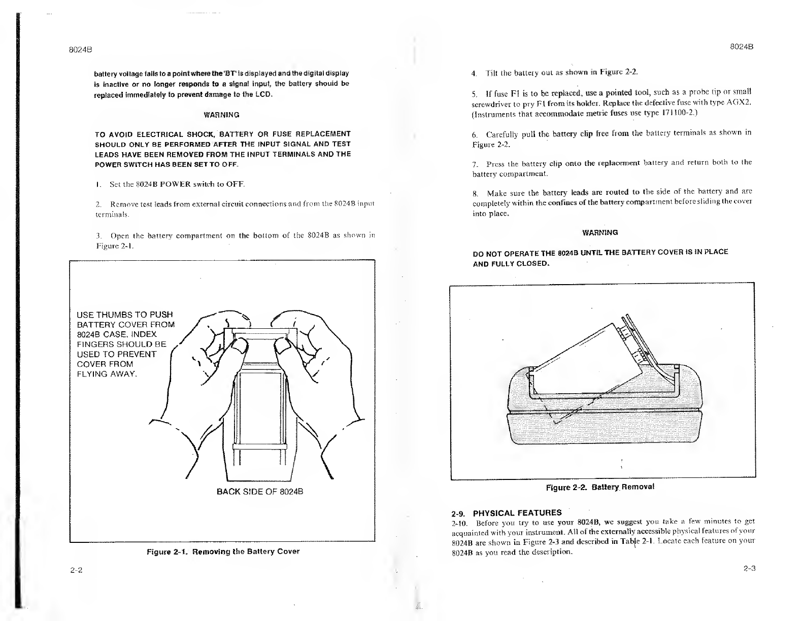
2-7. Battery or Fuse Installation/Replacement
2-8. Your 8024B is designed to operate on asingle, inexpensive, 9V battery of the
transistor radio/ calculator variety (NEDA 1604). When you receive your 8024B, the
battery will not be installed in the DMM. Once the battery is installed, you can expect a
typical operating life of up to 100 hours with an alkaline battery or 50 hours with acarbon-
zinc battery. Wrhen the battery has exhausted about 80% of its useful life the BT indicator
will appear in the upper left corner of the display. Your 8024B will operate properly for at
least 10 hours on an alkaline battery after BT appears in the display. Use the following
procedure to install or replace the battery or fuse:
CAUTION
To ensure operation within the accuracy specifications, the battery should be
replaced when the voltage measured at the center of the battery eliminator
connector falls below -3.00 volts (with respect to the COMMON input). If the
2-1

8024B 8024B
battery voltage falls to apoint where the ‘BT1is displayed and the digital display
is inactive or no longer responds to asignal input, the battery should be
replaced immediately to prevent damage to the LCD.
WARNING
TO AVOID ELECTRICAL SHOCK, BATTERY OR FUSE REPLACEMENT
SHOULD ONLY BE PERFORMED AFTER THE INPUT SIGNAL AND TEST
LEADS HAVE BEEN REMOVED FROM THE INPUT TERMINALS AND THE
POWER SWITCH HAS BEEN SET TO OFF.
1.Set the 8024 BPOWER switch to OFF.
2. Remove test leads from external circuit connections and from the 8024B input
terminals.
3. Open the batten' compartment on the bottom of the 8024B as shown in
Figure 2-1.
Figure 2-1. Removing the Battery Cover
4. Tilt the battery out as shown in Figure 2-2.
5. If fuse FI is to be replaced, use apointed tool, such as aprobe tip or small
screwdriver to pry FI from its holder. Replace the defective fuse with type AGX2.
(Instruments that accommodate metric fuses use type 171100-2.)
6. Carefully pull the battery clip free from the battery terminals as shown in
Figure 2-2.
7. Press the battery clip onto the replacement battery and return both to the
battery compartment.
8. Make sure the battery leads are routed to the side of the battery and are
completely within the confines of the battery compartment before sliding the cover
into place.
WARNING
DO NOT OPERATE THE 8024B UNTIL THE BATTERY COVER IS IN PLACE
AND FULLY CLOSED.
LI
Figure 2-2. Battery Removal
2-9. PHYSICAL FEATURES
2-10. Before you try to use your 8024B, we suggest you take afew minutes to get
acquainted with your instrument. All of the externally accessible physical features of your
8024B are shown in Figure 2-3 and described in Table 2-1. Locate each feature on your
8024B as you read the description.
2-2 2-3

8024B 8024B
Figure 2-3. Controls, Indicators and Connectors
Table 2-1. Controls, Indicators, and Connectors
ITEM
NO. NAME FUNCTION
1Display A3!/a digit display (1999 max) with
decimal point and minus polarity indi-
cation. Used to indicate measured input
values, overrange condition, low bat-
tery condition and level.
2Battery Eliminator
Connector
An external input power connector for
use with the Model A81 Battery Elimi-
nator accessory. (A81 is available in a
variety of voltage and plug configura-
tions. See Section 6.)
3Battery Compartment
and Cover
Cover for the 9V battery and current-
protection fuse FI .Refer to figure 2-1
for battery cover removal instructions.
Table 2-1. Controls, Indicators, and Connectors (cont)
ITEM
NO. NAME FUNCTION
4V/fl/S Input Protected test lead connector used as
Connector the high input for all voltage, conduc-
tance, continuity, level detector, and
resistance measurements. This con-
nector will accept standard banana
plugs.
fi
5COMMON Input
Connector
Protected test lead connector used as
the low or common input for all mea-
surements. Will accept banana plugs.
u6mA/° CInput Protected test lead connector used as
Connector the high input for all current and tem-
perature.
1•7Function Switch Apush-push switch (push on -push
&
%,
W-
j£:
mA/° C/V/fi/S off, do not pull to select afunction),
which works in conjunction with the
high input connectors and the TEMP
°Cswitch to select DMM measurement
function.
8Range Switches Interlocked push-button switches for
selecting ranges, i.e., pressing the
desired range switch selects that range
and cancels previous switch depres-
sions. Do not pull switches to select a
range.
Voitage: 200 mV, 2V, 20V, 200V, 1000V
dc/750V ac
Current: 2mA, 20 mA, 200 mA, 2000 mA
Resistance: 200R 2kR 20 kR 200
kR 2000 kR 20 MS2
Conductance: 200 nS (S =Siemens =
1/Rv= international unit of conduc-
tance). Requires simultaneous depres-
sion of two range switches.
Temperature: °C
9Tilt Bail Aremovable fold-out stand which
allows the instrument to be either tilted
for bench-top use or hung from ahook
in the absence of awork area.
2-4 2-5

8024B 8024B
Table 2-1. Controls, Indicators, and Connectors (cont)
ITEM
NO. NAME FUNCTION
10 DC/AC/Audible tone Apush-push switch (push on -push
Switch off, do not pull). When using Vor mA
functions, the in position selects AC
measurement functions and the out
position selects the DC measurement
function. When used with fZ or Sfunc-
tions, the in position enables the audi-
ble tone feature and the out position
disables the audible tone feature.
11 PEAK HOLD Switch Apush-push switch (push on -push
off, to the right only, do not push or pull
to the left), that enables or disables the
Peak-Hold function.
12 POWER Switch Aslide switch used to turn the instru-
ment off and on.
2-11. OPERATING NOTES
2-12. The following paragraphs will familiarize you with the capabilities and limitations
of your Model 8024B.
2-13. Input Overload Protection
CAUTION
Exceeding the maximum input overload limits can damage your instrument.
The transient overload protection circuit is intended to protect against short
duration high energy pulses. The components used limit the protection to
approximately five pulses per second for 6kV, lOmicrosecond pulses, and
about 0.6 watts average for lower pulses. Fast rep rate pulses as from aTV set
can damage the protection components; RV1 -RV4, R1 and R2*, it replaced,
use only Fluke replacement parts to maintain product safety. *R2 is afusable
resistor. Use exact replacement to insure safety.
2-14. Each measurement function and its associated ranges are equipped with input
overload protection. The overload limits for each function and range are given in Table 2-
2.
2-15. input Connection to COMMON
WARNING
Table 2-2. Input Overload Limits
SELECTED
FUNCTION INPUT
TERMINALS MAX. INPUT OVERLOAD
Voltage V/12/S and
COMMON 1000V dc or peak ac on all ranges
except 200 mV (15 sec max above
300V dc or rms).
Current and
Temperature mA -°C and
COMMON 2A maximum, fuse protected to 600V
dc/ac rms.
DO NOT USE ABOVE 600V.
Resistance,
Continuity,
Level Detector
and Conductance
V/S2/S and
COMMON 500V dc/ac rms.
Any COMMON 500V dc/ac rms with respect to earth
ground.
2-16. The 8024B may be operated with the COMMON input terminal at apotential of up
to 500V dc or 500V mis ac above earth ground. If this limit is exceeded, instrument
damage may occur. This, in turn, may result in asafety hazard for the operator.
2-17. Fuse Check
2-18. The current (m.A) function contains two fuses. Check them as follows:
1.Complete the setup steps for the RESISTANCE (ft) function and select the 2
kfl range.
2. Touch the red test probe to the rnA input jack so that the V-ft input and mA
input are connected together.
3. If the display reads approximately .100 kft, both fuses are good.
4. If the display reads overrange 1followed by blank digits, one or both fuses need
replacement. See the following paragraph for replacement instructions.
2-19. Fuse Replacement ,
2-20. All ac and dc current ranges are fuse protected. Two series fuses are used: (i) FI,
2A/ 250V, replaceable at the battery compartment (see Section 2"‘Battery or Fuse
Installation/ Replacement”) and (2) F2, 3A'600V battery fuse {see Section 4
“Battery/ Backup Fuse Replacement”).
WARNING
2-6
TO AVOID ELECTRICAL SHOCK AND/OR INSTRUMENT DAMAGE, DO
NOT CONNECT THE COMMON INPUT TERMINAL TO ANY SOURCE OF
MORE THAN 500 VOLTS DC OR 500V RMS AC ABOVE EARTH GROUND.
TO AVOID ELECTRICAL SHOCK DO NOT OPERATE THE 8024B UNTILTHE
BATTERY COVER IS IN PLACE AND FULLY CLOSED.
2-7

8024B 8024B
2-21. The Display
2.22 As Figure 2-4 shows, your 8024B has a3-1 /2digit liquid crystal display. Displayed
values can range from 000 through 1999(1999 is rounded to 2000 for ease of discussion).
The decimal point position is determined by the selected range and is independent of
selected function, except temperature. When the °Cfunction is selected, the decimal point
is not displayed. If the dc voltage or current measurement function is selected, the minus
sign indicates that the input signal is negative with respect to the COMMON input
terminal. If the °C measurement function is selected, the minus sign indicates that the input
temperature is below zero. The absence of aminus sign indicates apositive reading. The
minus sign is also used in conjuncton with the up and down ^arrows when analyzing the
input signal using the level detector function.
NOTE
The minus sign (-) may flash momentarily as the 8024B comes out ofan
overrange condition. This will most likely he seen in the ohms mode as the
open circuit test leads are applied to an in-range resistance value. If the
minus sign remains on for in-range ohms readings, the circuit is live (a
negative voltage is present at the input terminals due to chargedcapacitors,
etc.) and incorrect resistance readings will he displayed.
Figure 2-4. Display
2-23. The up and down ^arrows (above and below the minus sign) are enabled by
selecting the resistance or conductance functions. These arrows are visual indicators for
the continuity and level detector functions.
2-24. The display has two abnormal status indicators (Figure 2-5), low battery power
and instrument overrange. ABT is displayed when approximately 20% of battery life
remains (battery replacement is indicated). A1followed by three blanked digits is
displayed (decimal point may be present) as an overrange indication. It means that the
next higher range should be selected. It does not necessarily mean that the instrument is
being exposed to a damaging input condition. For example, when measuring resistance an
open-input will cause an overrange indication.
NOTE
When the 8024 Bis powered with the A-81 Battery Eliminator the '‘BT'
indicator may come on. However, instrument operation will he normal.
2-25. The liquid crystal display used in the 8024B is arugged and reliable unit which will
give years of satisfactory service. Display life can be extended by observing the following
practices:
1. Protect the display from extended exposure to bright sunlight.
2. Keep the multimeter out of high temperature, high humidity environments
(such as the dash of acar oh ahot, sunny day). Otherwise the display may
temporarily turn black. Recovery occurs at normal operating temperature.
3,
The display operation may be slowed in extremely low temperature
environments. No damage will occur to the LCD, but response time is greatly
increased. Recovery occurs at normal operating temperature.
2-26. OPERATION
2-27. The following paragraphs describe how to operate your 8024R in each of its nine
functions. Proceed to the description for the function you want to use.
2-28. AC/DC Volts (V) Operation
2-29. Figure 2-6 shows operation for the voltage measurement function. Perform each of
the steps listed in sequence and comply with the? warning.
2-30. AC/DC Current (mA) Operation
2-31. Figure 2-7 shows operation for the current measurement function. Perform each of
the steps listed in sequence and comply with the warning.
2-32. Resistance (Q) Operation
2-33. Figure 2-8 shows operation for the resistance measurement function. To make
resistance measurements, complete each of the steps listed in the figure sequentially, and
comply with the warning.
2-8 2-9

8024B 8024B
The PEAK-HOLD switch and Function switches are push-push
type. Operate these switches by pushing to the RIGHTSonly!
Do not push or pull these switches to the left (out or off) positions.
•Connect the test leads as shown above,
•Depress the grey switch beside the range desired (20V is
shown selected).
•Set the AC/DC switch out for DC or in For AC (DC is shown
selected). WARNING
TO AVOID ELECTRICAL SHOCK AND/OR INSTRUMENT DAMAGE,
DO NOT CONNECT THE 8024B TERMINALS TO SOURCES THAT
EXCEED THE FOLLOWING LIMITS WHEN MEASURING
VOLTAGES:
COMMON: 50GV DC OR AC RMS WITH RESPECT TO EARTH
GROUND.
V-£2-S: 1000V DC OR 750V AC RMS WITH RESPECT TO THE
COMMON TERMINAL (IN THE 200mV RANGE, SOURCES
GREATER THAN 300V DC OR AC RMS SHOULD NOT BE CON-
NECTED LONGER THAN 15 SECONDS).
•Connect the test leads to the circuit being measured.
•Read the measured value on the display. The minus sign will
appear if the V-fi- Sterminal is negative with respect to the
COMMON terminal.
Figure 2-6. Volts Operation
The PEAK-HOLD switch and Function switches are push-push
type. Operate these switches by pushing to the RIGHT only!
Do not push or pull these switches to the left (out or off) positions.
•Connect the test leads as shown.
•Depress the grey switch beside the range desired (20 mA range
shown selected).
•Set the AC/DC switch out for DC or in for AC.
•Insure that all other switches are at the out or OFF positions.
WARNING
TO AVOID ELECTRICAL SHOCK AND/OR INSTRUMENT DAMAGE,
DO NOT CONNECT THE 8024B TERMINALS TO SOURCES THAT
EXCEED THE FOLLOWING LIMITS WHEN MEASURING
CURRENT:
COMMON: 500V DC OR AC RMS WITH RESPECT TO EARTH
GROUND.
mA-°C: CURRENT OF 2AMPS OR bPEN CIRCUIT VOLTAGE OF
600V DC/AC RMS.
•Connect the test leads to the circuit being measured.
•Read the measured value on the display. In DC the minus sign
will appear if the mA-°C terminal is negative with respect to
the COMMON terminal.
Figure 2-7. Current Operation
2-10 2-11

8024 B8024
B
*NOTE:
The PEAK-HOLD switch and Function switches are push-push
type.Operate these switches by pushing to the RIGHT only!
Do not push or pull these switches to the left (out or off) positions.
•Connect the test leads as shown.
•Depress the mA-°C-V-£2-S switch.
•Depress the grey switch beside the range desired (20k is shown
selected.
•Insure that all other switches are at the out or OFF positions.
•Make sure that the device being measured contains no elect-
rical energy. WARNING
TO AVOID ELECTRICAL SHOCK AND/OR INSTRUMENT DAMAGE,
DO NOT CONNECT THE 8024B TERMINALS TO SOURCES THAT
EXCEED THE FOLLOWING LIMITS WHEN MEASURING
RESISTANCE OR CONTINUITY:
COMMON: 500V DC OR AC RMS WITH RESPECT TO EARTH
GROUND.
V-H-S: 500V DC OR AC RMS WITH RESPECT TO THE COMMON
TERMINAL.
•Connect the test leads across the device being measured.
•Read the measured value on the display.
Figure 2-8. Resistance Operation
2-34. Continuity Testing
2-35. The 2kfl range of your 8024B can be used to make fast continuity tests. Select the 2
kfl range, fl function, and depress the AC/DC switch (to enable the audible alarm). The A
up arrow will appear in the display. If continuity is measured between the test lead tips
(touch the tips together momentarily), the audible tone will sound, then the upAat row will
disappear from the display and the downYarrow will appear. Typically, 600ft or less will
activate the down arrow and audio tone. Comply with the kfl warning.
2-36. Diode Testing
2-37. The 2kfl, 200 kfl, and 20 Mfl ranges of the kfl function will turn on PNjunctions.
The 2kfl is preferred and is marked with adiode symbol on the front panel of your 8024B.
The open circuit voltage is less than 3.5V on the 2 kfl range and less than 1.5V on all other
ranges. When testing diodes in conjunction with the audio tone, use the 200 kfl range.
.NOTE
The 200fl, 20 kfl. ami 2000 kfl ranges can he usedfor in-circuit resistance
measurements.
2-38. Conductance (S) Operation
2-39. Figure 2-9 shows operation for the conductance measurement function. To make
conductance measurements, complete each of the steps listed in the figure sequentially,
and comply with the warning. Siemens, the displayed units, is equal to IMl. For the
resistance equivalent to the displayed value, refer to the conductance-to-resistance
conversion material presented later in this section under Measurement Techniques.
2-40. Temperature (°C) Operation
WARNING
TO AVOID ELECTRICAL SHOCK, DO NOT USE THE THERMOCOUPLE
ACCESSORIES WHEN VOLTAGES EXCEEDING 30V AC RMS OR 60V DC
ARE PRESENT. THE PROBE TIP MAY BE ELECTRICALLY CONNECTED TO
THE ACCESSORY OUTPUT TERMINALS.
2-41. Figure 2-10 describes operation for the temperature measurement function with
the thermocouple accessories and with the John Fluke Model 80T-I50 Temperature
Probe. To find the Fahrenheit equivalent oj[ the °C display, go to the Temperature
Conversion portion of the Measurement Techniques material presented later in this
section.
NOTE
Thermocouple connections must he made using approved isothermal
connectors (such as the Y8104) and thermocouple wire that is the same type
as the thermocouple. Failure to use these materials will result in erroneous
temperature measurement.
2-12 2-13

8024
B
CONDUCTANCE (S) {Use for measuring resistances above 20 MH)
//V7
////
•LOW(-)
-HIGH(+)
DEPRESS BOTH AT /X':CO ////
SAME TIME FOR S///
RANGE /
|N for s//
FUNCTION*" //
*NOTE:
The PEAK-HOLDswitch and Function switches are push-push
type. Operate these switches by pushing to the RIGHT only!
Do not push or pull these switches to the left (out or off) positions.
•Connect the test leads as shown.
•Depress the mA-C-V-fi-S function switch.
•AT THE SAME TIME, depress both of the grey Srange switches.
•Insure that all other switches are at the out or OFF positions.
•Insure that the device being measured contains no electrical energy.
WARNING
TO AVOID ELECTRICAL SHOCK AND/OR INSTRUMENT DAMAGE,
DO NOT CONNECT THE 8024B TERMINALS TO SOURCES THAT
EXCEED THE FOLLOWING LIMITS WHEN MEASURING
CONDUCTANCE:
COMMON: 500V DC OR AC RMS WITH RESPECT TO EARTH
GROUND.
V-O-S: 500V DC OR AC RMS WITH RESPECT TO THE COMMON
TERMINAL.
•Connect the test leads across the device being measured (connect the
red test lead to the +end of polarized capacitors for leakage measure-
ments.
•Read the measured value in the display.
•See Measurement Techniques section for Conductance-Resistance
Conversion chart.
Figure 2-9. Conductance Operation
2-14
8024
B
TEMPERATURE (°C)
THERMOCOUPLE
ACCESSORY
(FOR 80T-150
SEE TEXT)
IN FOR TEMP'
3CRANGE X'sxTV s.
OUT FOR C//
FUNCTI
O
N*XX .F' /
*(SEE NOTE ON CONDUCTANCE PAGE) //
WARNING
TO AVOID ELECTRICAL SHOCK AND/OR INSTRUMENT DAMAGE,
DO NOT EXCEED THE MAXIMUM VOLTAGE AND TEMPERATURE
LIMITS FOR THE ACCESSORY USED.
John Fluke Thermocouple ACCESSORIES
•Connect the thermocouple termination across the mA- Cand
Common terminals with the TEMP side plugged into the
mA-°C terminal,
•Depress the grey TEMP °C range switch.
•Insure that all other switches are at the out or OFF positions.
•Read the measured value in the display. See Measurement
Technique section for °F conversion.
•If unit fails to function properly, see FUSE CHECK para. 2-1 7.
John Fluke 80T-150 ACCESSORY
•Connect the 80T-150 termination across the V-O-S and COMMON
terminals with the HI side plugged into the V-ST-S terminal.
•Select the appropriate range {200 mV or 2V).
•Insure that all other switches are at the out or OFF positions.
•Set the 80T-1 50 POWER switch to the ON position and read the
display in units indicated on the accessory label.
Figure 2-10. Temperature Operation
2-15

8024B 8024B
2-42. Not all applications for temperature measurement use just one thermocouple. The
applications material at the end of this section describes how to use your 8024B to
sequentially measure different thermocouples of the same type. Your 8024B is intended for
use with K-ty.pe thermocouples, if you use another type of thermocouple, the
measurement will be in error. See the Temperature Measurement Techniques material
presented later in this section.
2-43. Level Detector Operation WARNING
TO AVOID ELECTRICAL SHOCK AND/OR INSTRUMENT DAMAGE, DO
NOT CONNECT THE 8024B TERMINALS TO SOURCES THAT EXCEED THE
FOLLOWING LIMITS WHEN USING THE LEVEL DETECTOR FUNCTION:
COMMON: 500V DC OR 500V AC RMS WITH RESPECTTO EARTH GROUND
V/O/S: 500V DC OR 500V AC RMS WITH RESPECT TO THE COMMON
TERMINAL.
2-44. Use the level detector function for sensing logic levels and other active signals less
than 250V dc or ac rms in amplitude. Select the 200 kfl range on the Ofunction. The 200
kfi range is marked with astep function symbol (_T) on the front panel of your 8024B to
indicate its use in the level detector function. The level detector compares the input signal
to a+0.8 V(nominal) reference. There is both audible and visual indication of the results of
the comparison. The audible indication is a 2 kHz tone that can be enabled by depressing
the AC/ DC switch or disabled by releasing the AC/ DCswitch. The visual indication is an
up and/or down arrow that appears on the display above and/or below the minus sign
position. Figure 2-1 1shows (he indications for some typical input signals. Starting from
left to right:
1.The level is above the +0.8Vreference so the Aup arrow appears in the display
and the audible tone does not sound.
2. The input level is below the +0.8V reference, but above OV. The audible tone
sounds and iheTdown arrow appears in the display but the minus sign is absent.
3. The input levgl is below both the +0.8V reference and OV, TheVdown arrow
appears, the tone is audible, ar.d the minus sign appears.
4. The input signal is very near 0V. TheYdown arrow appears, the audible tone
Sounds, and the minus sign flickers off and on.
5. The input is atrain of pulses that pass above +0.8V but whose average value is
positive. Each time apulse goes above +0.8V, the Aup arrow appears and the
audible tone is silent. Each time the pulse goes below +0.8V, the Vdown arrow
appears and the audible tone sounds. The minus sign does not appear. For afast
pulse train, both arrows will be on.
6. The input signal is asine wave whose positive peaks pass above +0.8V but
whose average value is negative. The audible tone and arrows behave as described
in step 5 and the minus sign appears in the display.
2-16
7.
For short pulses, your 8024B has apulse stretcher circuit that captures and
holds the pulses long enough for the display and tone to respond, typically for 100
ms. The input impedance of the level detector is >100 kfl so as not to load logic
circuits. The level detector is also usable on the 2 kfl range. On this range, the
reference level is +0.4V nominal. See Measurement Techniques for additional
information.
2-45. Peak Hold Operation
CAUTION
The PEAK HOLD switch is apush-push type. Operate this switch by pushing to
the right only. Do not push or pull the switch to the left (off).
2-46. The peak hold function provides short term memory of the most positive dc or ac
rms level (Figure 2-12). The peak hold function is intended to be used for voltage and
current measurements. Proceed with the steps of operation for the measurement function
being used with the peak hold function. When the test leads have been connected to the
circuit to be measured, set the PEAK HOLD switch to ON. For anew reading, set the
PEAK HOLD switch to OFF then back to ON. To read negative peak signals, reverse the
test connections. An example peak hold operation would be as follows:
1. Set the PEAK HOLD switch to OFF.
2. Select the DC, V(volts) functions.
3. Insert the red test lead into the V/fl/S input, and select the 20V range.
4. Locate the battery eliminator connector on the right side of the unit.
2-17

8024B 8024B
5. Measure the voltage on the side contact (bottom of hole) of the connector
(approximately +2.90V).
6. Set the PEAK HOLD switch to ON and momentarily touch the test lead to the
side contact.
7. The reading should be the same as step 5, within afew digits.
8. False readings may result if the range or function switches are changed while
the PEAK HOLD switch is set to ON. To avoid these errors, reset the PEAK
HOLD circuit after each range or function change.
9. Static electricity and noise pickup may cause errors when using the PEAK
HOLD function. While the PEAK HOLD switch is ON, avoid touching the probe
tips to fingers or other objects which may contain astatic charge. The potential for
noise pickup is worst whenever the test leads are open circuited. This is particularly
true on the 200 mV, 2V and 2mA ranges. Refer to AC/ DC current measurement
section of MEASUREMENT TECHNIQUES for additional information.
2-47. INITIAL CHECK-OUT PROCEDURE
2-48. Now that you have installed the battery, and know where everything is and how it
works, let’s make sure that the unit is working properly. We'll run through asimple check-
out procedure starting with turn-on. No equipment other than test leads will be required.
If aproblem is encountered, please check battery, fuse, switch setting, and test lead
connection before contacting your nearest John Fluke Service Center,
NOTE
This procedure is intended to verify overall instrument operation, and is not
meant as asubstitute for theformal Performance Tests given in Section 4.
Limits shown exceed the specifications because the procedure uses one
measurement to check another.
1. Set the POWER switch to OFF and all range and function switches to the
released (out) position.
2. Set the POWER switch to ON and observe the display. It should read between
-00.1 and 00. L
3. Connect the red test lead to the V/IT/ Sinput terminal. Depress fl function
switch to select fl function.
4. Touch the red probe tip to the COMMON input terminal, and sequentially
depress each of the six dark range switches starting at the top (20 Mfl). The display
should read zero ±1 digit and the decimal point should be positioned as follows:
a. 20 Mil -0.00
b. 2000 kfl -000
.c. 200 kfl -00.0
d. 20 kfi -0.00
e. 2kfl -.000
f. 200(1 -00.0
5. Press the 20V range switch and remove the probe from the COMMON input
terminal. Release function switch to select volts function.
NOTE
For DC voltages and currents, the peak holdfunction measures the “most
positive” value of the input waveform. If the "most positive’’ excursion of
the waveform is negative with respect to common, anegative sign will be
displayed, i.e., when anegative sign is display, the measuredvalue is not the
negative peak, but is, instead the least negative (or mostpositive)portion of
the applied waveform.
10.
PEAK HOLD accuracy may be affected by mechanical shock. If your 8024B
has suffered mechanical shock during apeak measurement, reset the PEAK
HOLD circuit and repeat the measurement.
6. Look inside the battery eliminator connector on the right side of the 8024B arid
locate the connector contacts.
7. Touch the red probe to the center post of the battery eliminator Connector. The
display should read approximately -6.1V dc. (Note: this voltage varies with
condition and type of battery.)
8. Touch the probe tip to the side contact of the battery eliminator connector
located at the bottom of the hole. The display should read approximately 2.9V dc.
Notice that the sum of the two readings is equal to the battery voltage (typically 8to
J.0V dc). Remove the probe from the battery eliminator connector.
2-18
2-19

8024B 8024B
9. Depress the f! function switch and the AC/ DC switch; The Aup arrow wilt
appear in the display. Sequentially depress each of the six range switches. The
display will indicate an overrange condition and the decimal point will change
position.
10. Touch the red probe tip to the COMMON input terminal, the audible tone
will sound and theVdown arrow will appear in the display. Sequentially depress
each of the grey range switches. The display should read zero at each range setting.
Lead resistance may be sufficient to cause aone or two tenths {0.1 or 0.2fl)
indication on the 20011 range. Release the AC/ DC switch to silence the audio tone.
11. Touch the red probe tip to the mA -°C input connector and press the 2000
switch. The display should read 99.0 to 101.0.
21. Connect the test leads to the line voltage receptacle. You will hear the audible
tone modulated by the line frequency and see both arrows displayed.
22. Remove the test leads from the line power receptacle.
23. If your 8024B has responded properly to this point, it is operational and ready
for use.
2-49. MEASUREMENT TECHNIQUES
2-50. The following paragraphs offer you techniques that can improve the accuracy of
measurements made with your 8024B. While most of these techniques are in general use
throughout the electronics industry, these paragraphs offer specific information for use
with your 8024B. (Figure 2-13 presents atemperature correction factor for K-type
thermocouples.) Use this chart for accuracy enhancement above 300°C.
12. Press the 2kfl switch. The display should read .099 to .101. Remove the probe
from the mA -°C input connector.
13. Simultaneously depress the two range switches to select the 200 nS range. The
display should read 00.0 to 01.0(minimum conductance, maximum resistance),
14. Touch the red probe tip to the COMMON input terminal. An overrange
indication should be displayed since conductance is the reciprocal of resistance.
15. Connect the black test lead to the COMMON input connector.
16. Depress both the AC/DC switch and the 750V ac range switch. Set the
function switch to the voltage (out) position. (Use 750V range for 230V line.)
WARNING
THE LOCAL LINE VOLTAGE IS MEASURED IN THE FOLLOWING STEP. BE
CAREFUL NOT TO TOUCH THE PROBE TIPS WITH FINGERS, OR TO
ALLOW THE PROBE TIPS TO CONTACT EACH OTHER.
17. Measure the local ac line voltage at aconvenient output receptacle.
18. Set the PEAK HOLD switch to the ON position. The value of the line voltage
will be locked on the display. The display value should decay no faster than 1digit
per second. Set the PEAK HOLD switch to the OFF position.
19. Remove the test leads from the Sine power receptacle and set PEAK HOLD to
OFF, function to DC, PEAK HOLD to ON, and reinsert probes; observe 1.4! Xac
voltage. (This is the instantaneous peak of asingle half wave of line voltage.) Set
PEAK HOLD to OFF.
20. Select the 200 kfl range of the fi function switch (level detector), and depress
the AC/ DC switch (to enable the audible tone).
2-51. Temperature Conversion
2-52. The temperature measurements made with your 8024B are displayed in °C. ToEnd
the equivalent temperature in °F, either use the conversion tables in fable 2-3 or the
formula: 1.8 (°C)+ 32° =°F.
.. o. , ..... _*. :
—t
J
+20 C
.o
TYPICAL
rHERMC K-TYP
COUPLEE
[E
OK
ANS
-TYPE LIMITS
THERMC FOR
DCOUPL a™ /
U0
<
u.
Z
oo*U
—'C
\
V\v\///
—-IOC
1—
CJ
UJ
cc
I
l/
o-20 c
O
O
\_
—30 C
-10
ADD THE
TO THE C
EXAMPLE
0°
AP
ISP
E:
/
O
3 If
3RO
LAY
)MM
RO
KCTK
ERR
)0° 3C
PR1ATE
ED VAL
READS
VI PLOT,
JALTEIV
*-£
0° 500° 700° 900° 1100° 1300°
CORRECTION FACTOR
UE 5
+8O0°C.
CORRECTION FACTOR =-19°C
1PERATURE =800 -19 =781°C
=2.4%
Figure 2-13. Temperature Correction Factor for K-Type Thermocouples
2-20 2-21

8024B
Table 2-3. Celsius-to-Fahrenheii Conversion Scale (cont)
8024B
Table 2-3. Celsius-to-Fahrenheit Conversion Scale
Other manuals for 8024B
2
Table of contents
Other Fluke Multimeter manuals

Fluke
Fluke CNX 3000 User manual

Fluke
Fluke 8845A User manual

Fluke
Fluke 8845A User manual

Fluke
Fluke 12E User manual

Fluke
Fluke 8060A User manual

Fluke
Fluke 8020A User manual

Fluke
Fluke 87 III Series Operating and installation instructions

Fluke
Fluke 187 User manual

Fluke
Fluke 83 User manual

Fluke
Fluke 77 User manual