Fluke 233 Use and care manual

October 2009 ©2009 Fluke Corporation. All rights reserved. Specifications are subject to change without notice. 1
233
True-rms Remote Display Digital Multimeter
Calibration Information
Introduction
XWWarning
To avoid electric shock or injury, do not perform the performance tests or
calibration adjustment procedures unless qualified to do so.
The information provided in this document is for the use of qualified personnel
only.
The 233 Calibration Information provides the information necessary to adjust and verify the performance of the
Fluke Model 233 True-rms Remote Display Digital Multimeter (hereafter known as the Meter).
The following information is included in this document:
•Safety Information and International Electrical Symbols (page 2)
•Specifications (page 3)
•Testing the Fuse (page 9)
•Replacing the Fuse and the Battery (page 10)
•Cleaning (page 10)
•Performance Tests (page 11)
•Calibration Adjustment (page 14)
•Replacement Parts and Accessories (page 19)
•Complete Warranty (page 21)
See the 233 Users Manual for complete operating instructions.
Contact Information
To contact Fluke, call one of the following telephone numbers:
USA: 1-888-99-FLUKE (1-888-993-5853)
Canada: 1-800-36-FLUKE (1-800-363-5853)
Europe: +31 402-675-200
Japan: +81-3-3434-0181
Singapore: +65-738-5655
Anywhere in the world: +1-425-446-5500
To register your product, visit register.fluke.com

233
Calibration Information
2
Safety Information
A Warning identifies hazardous conditions and actions that could cause bodily harm or death.
A Caution identifies conditions and actions that could damage the Meter, the equipment under test, or cause
permanent loss of data.
XWWarning
To prevent possible electrical shock or personal injury, follow these guidelines:
•Use this Meter only as specified in this manual or the protection can be compromised.
•Do not use the Meter if it is damaged. Before you use the Meter, examine the case. Look
for cracks or missing plastic. Carefully look at the insulation around the terminals.
•Make sure the battery door is closed and locked before you operate the Meter.
•Replace the batteries when the battery indicator () appears.
•Remove the test leads from the Meter before the battery door on the Meter base is
opened.
•Examine the test leads for damaged insulation or exposed metal. Measure the test leads
for continuity. Do not use if resistance is high or noisy. Replace damaged test leads
before you use the Meter.
•Do not apply more than the rated voltage, shown on the Meter, between the terminals or
between a terminal and earth ground.
•Do not operate the Meter with the battery door removed or the case open.
•Be careful around voltages >30 V ac rms, 42 V ac peak, or 60 V dc. These voltages pose
a shock hazard.
•Use only the replacement fuse specified by the manual.
•Use the correct terminals, function, and range for measurements.
•Do not work alone.
•For current measurements, connect the Meter to the circuit after you remove circuit
power. Always put the Meter in series with the circuit.
•Connect the common test lead before the live test lead and remove the live test lead
before the common test lead.
•Do not use the Meter if it operates incorrectly. Protection can be compromised. If you
are unsure, have the Meter examined.
•Do not use the Meter around explosive gas, vapor or in damp or wet environments.
•Use only specified 1.5-V AA batteries (three in the Meter base and two in the display),
correctly installed, for Meter power.
•Comply with local and national safety requirements when in hazardous locations.
•Only use test leads that have the same voltage, category, and amperage ratings as the
Meter and that are approved by a safety agency.
•Measure a known voltage first to make sure that the Meter operates correctly. If you are
unsure, have the Meter examined.
•Use protective equipment, as directed by local or national authorities when in
hazardous work areas.
•Use only specified replacement parts in the Meter.
•Keep fingers behind the finger guards on the probes.

True-rms Remote Display Digital Multimeter
International Electrical Symbols
3
WCaution
To prevent damage to the Meter or to the equipment under test, follow these
guidelines:
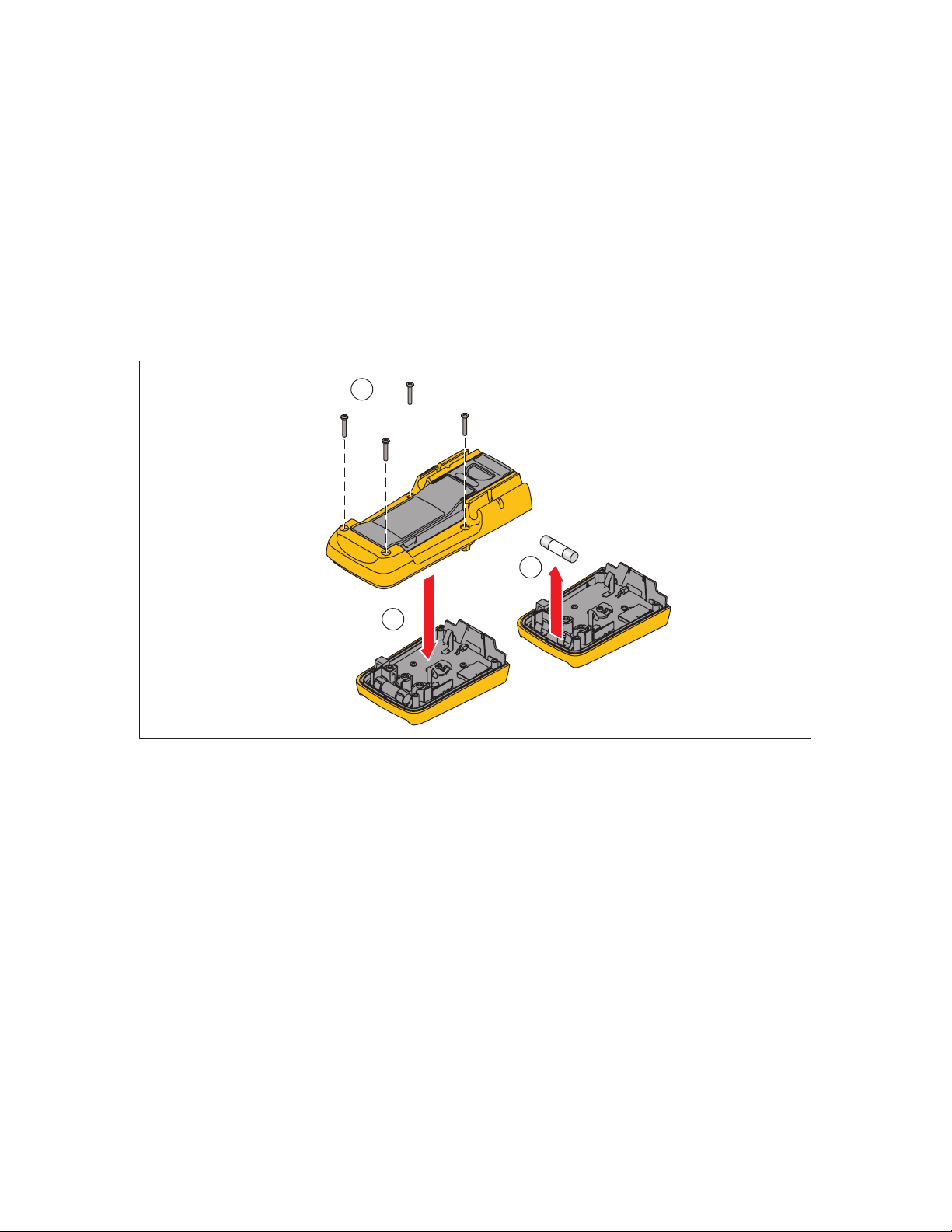
•Disconnect circuit power and discharge all high-voltage capacitors before you do diode
tests or measure resistance, continuity, or capacitance.
•Use the correct terminals, function, and range for all measurements.
•Before a current measurement, do the fuse test.
International Electrical Symbols
Table 1 lists the international symbols that appear in this document and on the Meter.
Table 1. Electrical Symbols
BAC (Alternating Current) JEarth ground
FDC (Direct Current) IFuse
XHazardous voltage PConforms to European Union directives.
WRisk of Danger. Important information.
See Manual. )Conforms to relevant Canadian Standards Association
directives.
Battery. Low battery when shown. TDouble insulated
RContinuity test or continuity beeper tone. ECapacitance
CAT
III
IEC Measurement Category III
CAT III equipment has protection against
transients in equipment in fixed-
equipment installations, such as
distribution panels, feeders and short
branch circuits, and lighting systems in
large buildings.
CAT
IV
IEC Measurement Category IV
CAT IV equipment has protection against transients
from the primary supply level, such as an electricity
meter or an overhead or underground utility service.
~Do not discard this product as unsorted
municipal waste. Go to the Fluke website
for recycling data.
ODiode
®Examined and licensed by TÜV Product
Services. ;Conforms to relevant Australian standards.
General Specifications
Maximum voltage between any
terminal and earth ground ........................................... 1000 V rms
WFuse for A inputs ..................................................... 11 A, 1000 V 17000A interrupt rating Fuse
Display ........................................................................... 6000 counts, updates 4/sec (Frequency: 9,999 counts, Capacitance: 1,000 counts)
Altitude
Operating.................................................................... 2,000 meters
Storage ....................................................................... 12,000 meters
Temperature
Operating.................................................................... -10 °C to +50 °C
Storage ....................................................................... -40 °C to +60 °C
Temperature coefficient ............................................... 0.1 X (specified accuracy) / °C (< 18 °C or > 28 °C)
Electromagnetic Compatibility (EN 61326-1:2006) .... In an RF field of 3 V/m, accuracy = specified accuracy except in temperature: specified
accuracy ±5 °C (9 °F)
Wireless Frequency...................................................... 2.4 GHz ISM Band 10 meter range

233
Calibration Information
4
Relative Humidity.......................................................... Maximum noncondensing
90 % at 35 °C
75 % at 40 °C
45 % at 50 °C
0 % to 70 % for 40 MΩrange
Battery Type
Meter base.................................................................. Three AA Alkaline batteries, NEDA 15A IEC LR6
Display module ........................................................... Two AA Alkaline batteries, NEDA 15A IEC LR6
Battery Life .................................................................... 400 hrs typical (Alkaline)
Shock ............................................................................. 1 Meter drop 6 sides per IEC 61010
Size (H x W x L) ............................................................. 5.3 cm x 9.3 cm x 19.3 cm
Weight ............................................................................ 604 g (1.3 lbs)
Safety Compliance........................................................ Complies with ANSI/ISA S82.01-2004, CSA 22.2 No. 61010-1-04 to 1000 V Measurement
Category III and 600 V Measurement Category IV.
Certifications ................................................................. CSA, TÜV (EN61010), P, ;(N10140),VDE, GOST
Detailed Specifications
For all detailed specifications:
Accuracy is specified for 1 yr after calibration, at operating temperatures of 18 °C to 28 °C, with relative humidity at 0 % to 90 %. Accuracy
specifications take the form of ±([ % of Reading ] + [ Number of least significant digits ]).
AC Voltage
AC conversions are ac-coupled and valid from 1 % to 100 % of range.
Accuracy
Range [1] Resolution 45 – 500 Hz 500 Hz – 1 kHz
600.0 mV 0.1 mV
6.000 V 0.001 V
60.00 V 0.01 V
600.0 V 0.1 V
1000 V 1 V
±(1.0 % + 3) ±(2.0 % + 3)
[1] Crest factor of ≤3 at 4000 counts, decreasing linearly to 1.5 at full scale.
DC Voltage, Conductance, and Resistance
Function Range Resolution Accuracy
mV dc 600.0 mV 0.1 mV
6.000 V 0.001 V
60.00 V 0.01 V
600.0 V 0.1 V
V dc
1000 V 1 V
±(0.25 % + 2)
600.0 Ω0.1 Ω±(0.9 % + 2)
6.000 kΩ0.001 kΩ
60.00 kΩ0.01 kΩ
600.0 kΩ0.1 kΩ
6.000 MΩ0.001 MΩ
±(0.9 % + 1)
Ω
40.00 MΩ0.01 MΩ±(1.5 % + 2)
Continuity
The beeper is guaranteed on <20 Ω, and guaranteed off >250 Ω, and detects opens or shorts of 500 μs or longer.

True-rms Remote Display Digital Multimeter
Detailed Specifications
5
Temperature
Range Resolution Accuracy
[1]
-40 °C to +400 °C
-40 °F to +752 °F
0.1 °C
0.1 °F
±(1.0 % + 10)
±(1.0 % + 18)
[1] Temperature uncertainty (accuracy) does not include error of the thermocouple probe.
AC Current
Function Range Resolution Accuracy
(45 – 500 Hz)
6.000 A 0.001 A
A ac [1,2,3]
10.00 A 0.01 A ±(1.5 % + 3)
[1] All ranges are specified from 5 % of range to 100 % of range.
[2] Crest factor of ≤3 at 4000 counts, decreasing linearly to 1.5 at full scale.
[3] AC current >10 A is unspecified. 20 A continuous overload for 30 seconds maximum.
DC Current
Function Range Resolution Accuracy
6.000 A 0.001 A
A dc [1]
10.00 A 0.01 A ±(1.0 % + 3)
[1] DC current >10 A is unspecified. 20 A continuous overload for 30 seconds maximum.
Capacitance
Range Resolution Accuracy
1000 nF 1 nF
10.00 μF 0.01 μF
100.0 μF 0.1 μF
9999 μF 1 μF
±(1.9 % + 2) [1]
[1] >1000 μF: 5 % + 20
Diode
Range Resolution Accuracy
2.000 V 0.001 V ±(0.9 % + 2)
Frequency
AC coupled, 5 Hz to 50 kHz, for V ac; dc coupled, 45 Hz to 5 kHz for A ac switch position.
Range Resolution Accuracy
99.99 Hz 0.01 Hz
999.9 Hz 0.1 Hz
9.999 kHz 0.001 kHz
50.00 kHz 0.01 kHz
±(0.1 % + 2)

233
Calibration Information
6
Input Characteristics
Function Overload
Protection
Input
Impedance
(nominal)
Common Mode
Rejection Ratio
(1 kΩunbalance)
Normal Mode Rejection
L1100 V
rms
>10 MΩ<100
pF
> 100 dB at dc, 50 Hz
or 60 Hz > 60 dB at 50 Hz or 60 Hz
K1100 V
rms
>5 MΩ< 100
pF > 60 dB, dc to 60 Hz
Full Scale Voltage
Open Circuit
Test Voltage To 6 MΩ40 MΩ
Typical Short Circuit Current
Ω1100 V
rms <2.7 V dc <0.7 V dc <0.9 V
dc <350 μA
R1100 V
rms <2.7 V dc <300 mV dc <350 μA
E1100 V
rms <2.7 V dc <700 mV dc <350 μA
G1100 V
rms <2.7 V dc Up to 2.000 V dc 1.2 mA
MIN MAX Recording
Nominal Response Accuracy
100 ms to 80 % Specified accuracy ±12 counts for changes >200 ms in duration (±40 counts in ac)

True-rms Remote Display Digital Multimeter
Battery Replacement
7
Battery Replacement
XWWarning
To prevent incorrect measurements, possible electrical shock, or personal injury, replace
the battery when the battery indicator () appears. If the display shows , the
Meter will not function until the display module batteries are replaced. If the display shows
, the Meter will not function until the Meter-base batteries are replaced.
There are two low-battery indicators in the display: one for the Meter base batteries and one for the display module
batteries. Replace the batteries when the low-battery indicator shows.
2
1
3
4
gcc112.eps
Figure 1. Meter-Base Battery Replacement
To replace the batteries in the Meter base:
1. Turn the Meter off and remove all test leads.
2. Lift the tilt stand up as shown in Figure 1.
3. Turn the battery-door latch with a standard screwdriver until the unlocked symbol () aligns with the arrow.
4. Lift off the battery door.
5. Remove the three AA batteries and replace them with new ones. Use the correct battery orientation.
6. Install the battery door.
Turn the battery-door latch until the locked symbol () aligns with the arrow. When the Meter does not power on,
the Meter-base batteries or display-module batteries can be dead. To find which of the batteries to replace:
1. Dock the display module with the Meter base.
2. Turn the function switch to off and then on.
If the red high-voltage LED on the Meter base flashes, the Meter base batteries are good. Replace the display-
module batteries and turn the Meter on.

233
Calibration Information
8
Remove the Display Module
To remove the display module (see Figure 2):
1. Push in on the latches on the sides of the display module.
2. Pull the display module off of the top end of the Meter base.
The Meter base and display module can be a maximum of 10 Meters (30 feet) from each other before the radio
connection is broken. This distance can change if obstacles are between the Meter base and the display module.
There is a radio connection between the display module and Meter base when shows in the display.
When the display module and Meter base lose the radio connection, the display shows dashes and blinks.
Possible causes for this loss are the distance is too far for the environment or the batteries in the Meter base are dead.
To reconnect, decrease the distance between the display module and Meter base.
2
1
gcc114.eps
Figure 2. Display Module Separation
To replace the batteries in the display module:
1. Remove the display module from the Meter base. See the “Remove the Display” section.
2. Remove the battery door of the display module as shown in Figure 3.
3. Remove the two AA batteries and replace them with new ones. Use the correct battery orientation.
4. Replace the battery door on the display module.
Dock the display module with the Meter base and turn the Meter on.

True-rms Remote Display Digital Multimeter
Fuse Test
9
2
3
gcc111.eps
Figure 3. Display-Module Battery Removal
Fuse Test
To test the fuse:
1. Set the rotary switch to Ω.
2. Plug a test lead into the vjack and touch the probe to the 10A jack, as shown in Figure 0-4.
If the display shows a resistance value in the range of that shown in Figure 0-4, the fuse is good.
If the display reads 0L, replace the fuse and test again.
If the display shows any other value, have the Meter serviced. See “Contact Information” earlier in this document.
Good fuse: 0.0 Ω to 0.5 Ω
Replace fuse: OL
erc010f.emf
Figure 4. Fuse Test

233
Calibration Information
10
Fuse Replacement
To replace the fuse:
1. Remove the test leads from the Meter.
2. Remove the display module from the Meter base. See the “Remove the Display Module” section.
3. As shown in Figure 5, remove four screws from the case bottom.
4. Pull the case bottom from the case top.
5. Remove the fuse from its holder and replace it with an 11 A, 1000 V, FAST fuse with a minimum interrupt
rating of 17,000 A. Use only Fluke PN 803293.
To re-assemble the Meter, do the steps above in the opposite sequence.
3
5
4
gcc113.eps
Figure 5. Fuse Replacement
Cleaning the Meter
Wipe the case with a damp cloth and mild detergent. Do not use abrasives or solvents. Dirt or moisture in the
terminals can affect readings.

True-rms Remote Display Digital Multimeter
Performance Tests
11
Performance Tests
XWWarning
To avoid electric shock, do not perform the performance test procedures unless
the Meter is fully assembled.
The following performance tests verify the complete operation of the Meter and check the accuracy of each Meter
function against its specifications. The recommended calibration interval is 12 months. If the Meter fails any part of
the test, calibration adjustment and/or repair is indicated.
In the performance tests, the Meter is referred to as the unit under test (UUT).
Required Equipment
Table 2 lists the equipment required to conduct a performance test on the Meter.
Table 2. Required Equipment
Recommended Equipment Measurement Function Accuracy
DC Volts 10 mV to 600 V
±0.0625 %
DC Current 600 μA to 10 A
±0.25 %
AC Volts 6 mV to 600 V
±0.25 % @ 45 Hz to 1 kHz
AC Current 600 μA to 10 A
±0.375 % @ 45 Hz to 1 kHz
Resistance 0 to 5 MΩ
±0.225 %
10 to 30 MΩ
±0.39 %
Capacitance 9 to 900 μF
±0.475 %
5500A Multi-product Calibrator (or
equivalent)
Temperature 0 °C to 400 °C ±0.25 %
5500A Multi-product Calibrator (or
equivalent)
Frequency 2 V, 50 kHz
±0.025 %
Fluke 80 AK
K-type Thermocouple Adapter Accessory
Temperature
K-type Thermocouple, mini-plug on both
ends
Temperature

233
Calibration Information
12
Testing the Display
Push Kand turn the rotary switch to the eposition. Compare the display with the example in Figure 6.
Check all segments for clarity and contrast.
erc022f.emf
Figure 6. Display Segments
Backlight Test
To Test the Backlight, press Qand verify that the backlight comes on.
Keypad Test
To test the keypad, turn the Meter to ACV and push each button separately. Each button push should cause the
Meter to beep and activate a display annunciator.
Reset the Meter by turning it Off and then back to an on position.
Preparing for the Performance Tests
XWWarning
To avoid possible electric shock or personal injury:
•Do not perform the following procedures unless qualified to do so. Some
procedures involve the use of high voltages.
•Before handling the test connections and in between tests, make sure
the calibrator is in standby mode (STBY).
To prepare for the performance test:
1. Make sure that you have the required equipment (refer to Table 2).
2. Warm up the calibrator as required by its specifications.
3. Allow the temperature of the UUT to stabilize at room temperature (23 °C ±5 °C [73 °F ±9 °F] ).
4. Check the fuses and Battery, and replace them if necessary. Refer to “Fuse Test”, and “Fuse
Replacement”.
To verify the accuracy of the Meter functions, do the following:
1. Connect the Calibrator to the VΩand COM input terminals on the Meter.
2. Turn the rotary switch to the function listed in each step of Table 3.

True-rms Remote Display Digital Multimeter
Performance Tests
13
3. Apply the input level for each step listed in Table 3.
4. Compare the reading on the Meter display with the Display Reading in Table 3.
5. If the display reading falls outside of the range shown in Table 3, the Meter requires calibration
adjustment or repair.
Temperature Tests
Connect the K-type thermocouple to the temperature input of the Meter and temperature calibrator. To ensure an
accurate measurement, the Meter and the thermocouple connector must be at the same temperature. After connecting
the thermocouple to the Meter, allow the junctions to stabilize before recording the displayed reading. This can take
several minutes, depending on temperature gradients.
Table 3. Performance Tests
Step Function Range Applied Display Reading
1 600.0 0.0 Ω0.0 to 0.2
2 600.0 500 Ω495.3 to 504.7
3 6.000 k 5 kΩ4.954 to 5.046
4 60.00 k 50 kΩ49.54 to 50.46
5 600.0 k 500 kΩ495.4 to 504.6
6 6.000 M 5 MΩ4.954 to 5.046
7 40.00 M 10 MΩ9.83 to 10.17
8
e
Ohms
40.00 M 30 MΩ29.53 to 30.47
9 600 Ω20 ΩBeeper On
10
R
Continuity 600 Ω250 ΩBeeper Off
11 6.000 V 5V, 45 Hz 4.947 to 5.053
12 6.000 V 5V, 1 kHz 4.897 to 5.103
13 60.00 V 50 V, 45 Hz 49.47 to 50.53
14 60.00 V 50V, 1 kHz 48.97 to 51.03
15 600.0 V 600V, 45 Hz 593.7 to 606.3
16 600.0 V 600V, 1kHz 587.7 to 612.3
17
K
AC Volts
1000 V 1000 V, 500 Hz 977 to 1013
18 e
AC Volts + Hz 6.000V 2 v, 50 kHz[1] NA

233
Calibration Information
14
Table 3. Performance Tests (cont)
Step Function Range Applied Display Reading
19 6.000V 0V -0.002 to 0.002
20 6.000V 5V 4.985 to 5.015
21 60.00V 50V 49.85 to 50.15
22 600.0V 600V 598.3 to 601.7
23 600.0V -600V -598.3 to -601.7
24
L
DC Volts
1000V 1000V 995 to 1000
25 600.0 mV 6 mV, 45 Hz 5.6 to 6.4
26
m
AC Millivolts 600.0 mV 600mV, 1 kHz 587.7 to 612.3
27 600.0 mV 20 mV 19.7 to 20.3
28
E
DC Millivolts 600.0 mV 600mV 598.3 to 601.7
29 GDiode 2.000 V 1.9V 1.881 to 1.919
31 1000 nF 30 27 to 33
32 9 μF 8.81 to 9.19
35 90 μF 88.1 to 91.9
36
E
Capacitance
9999 μF 900 μF 881 to 919
Set calibrator to standby, reconfigure leads, and program for amps output
37 A
DC Amps 10.00 A 9.5 A 9.37 to 9.63
38 ?
AC Amps 6.000 A 5.0 A, 45 Hz 4.922 to 5.078
39 Open input 0PEn
40 0.0 °C -1.0 to 1.0
41
y
Temperature
400 °C 395.0 to 405.0
[1] If using a Fluke 9100 calibrator, the Calibrator Frequency mode must be used to obtain accurate frequency.
Calibration Adjustment
The Meter features closed-case calibration adjustment using known reference sources. The Meter measures the
applied reference source, calculates correction factors, and stores the correction factors in nonvolatile memory.
The following sections present the features and Meter pushbutton functions available during the Calibration
Adjustment Procedure. Should the Meter fail any of the performance tests, perform the Calibration Adjustment
Procedure.
Use the following steps to view the Meter’s calibration counter.
1. While pressing K, turn the rotary switch from OFF to Ωfunction. The Meter should display
“CAL”.
2. Press gonce to view the calibration counter. For example, “n001”

True-rms Remote Display Digital Multimeter
Calibration Adjustment
15
3. Turn the rotary switch to OFF.
Calibration Adjustment Password
To start the Calibration Adjustment Procedure, the correct 4-digit password must be entered. The default password is
“1234”. The password can be changed or reset to the default as described in following paragraphs.
Changing the Password
Use the following steps to change the Meter’s password:
1. While pressing K, turn the rotary switch from OFF to Ωfunction. The Meter should display
“CAL”.
2. Press gonce to see the calibration counter.
3. Press gagain to start the password entry. The Meter displays “????”
4. The Meter buttons indicated below represent the numbers 1 through 5 when entering or changing the
password:
K= 1 M= 2 q= 3 g= 4 Q= 5
5. Press 4 buttons to enter the current password. If changing the password for the first time, enter
K(1), M(2), q(3), and g(4).
6. Press qto change the password. The Meter displays “????” if the entered password is correct. If the
password is not correct, the Meter emits a double beep, displays “????”, and the password must be
entered again. Repeat step 5.
7. Press the 4 buttons of the new password.
8. Press gto store the new password.
Restoring the Default Password
If the calibration password is forgotten, the default password (1234) can be manually restored using the following
steps:
XW Warning
To avoid electric shock or personal injury, remove the test leads and any input
signal before removing the Meter’s back case.
1. Remove the Meter’s back case. Leave the PCA in the top case.
2. Apply 4.5 V across the battery contacts (XBT1) + and (XBT2) – on the back of the PCA. See Figure 7.
3. Turn the rotary switch from OFF to any on position.
4. Short across the S103 CAL keypad on the back of the PCA. See Figure 7. The Meter should beep. The
default password is now restored.
5. Remove the 4.5 V supply and replace the Meter’s back case.

233
Calibration Information
16
XBT102
XBT101
S103
erc12f.emf
Figure 7. Calibration Password Reset
Meter Buttons Used in the Calibration Steps
When performing the Calibration Adjustment Procedure, the Meter buttons behave as follows. This may be of help
in determining why a calibration step is not accepted and for determining the input value without referring to
Table 4.
1. Press and hold Kto show the measured value. The measured value is not calibrated so it may not
match the input value. This is normal.
2. Press and hold Mto display the required input value.
3. Press gto store the calibration value and advance to the next step. This button is also used to exit
calibration mode after the calibration adjustment sequence is complete.
4. Press Qto toggle the backlight on and off.
Calibration Adjustment Procedure
To adjust the Meter’s calibration, use the following steps:
Note
If the Meter is turned off before completion of the adjustment procedure, the calibration
constants are not changed.
1. While holding down K, turn the rotary switch from OFF to Ωfunction. The Meter should display
“CAL”.
2. Press gonce to see the calibration counter.
3. Press gagain to start the password entry. The Meter displays “????”.
4. Press the 4 button password.
5. Press gto go to the first calibration step. The Meter displays “C-01” if the password is correct. If the
password is not correct, the Meter emits a double beep, displays “????” and the password must be
entered again. Repeat step 4.
6. Apply the input value listed for each calibration adjustment step. For each step, select the rotary switch
position and apply the input to the terminals as indicated in the Table 4.

True-rms Remote Display Digital Multimeter
Calibration Adjustment
17
Note
Some adjustment steps require additional wait time after the calibrator settles, as noted in
Table 4.
7. After each input value is applied, press gto accept the value and proceed to the next step (C-02 and
so forth).
Notes
After pressing g, wait until the step number advances before changing the calibrator
source or turning the Meter’s rotary knob. Some adjustment steps can take up to several
seconds to execute before moving to the next step.
If the knob is not in the correct position for a given step, the meter will flash the unit
annunciators until the knob is put in a valid position. The keys that show the reading and
required input values are not allowed until the knob is correct.
Likewise, if the rotary switch is not in the correct position or the measured value is not within
the anticipated range of the input value, the Meter will emit a double beep and will not
continue to the next step when gis pressed.
8. After the final step, the display shows “End” to indicate that the calibration adjustment is complete.
Press gto return to meter mode.
Notes
Set the calibrator to Standby prior to changing the function switch position and after
completing adjustment of each function.
If the calibration adjustment procedure is not properly completed, the Meter will not operate
correctly.

233
Calibration Information
18
Table 4. Calibration Adjustment Steps
Rotary
Switch
Position
Calibration Steps Input
Terminals
Calibrator
Source Value
C-01 VΩ/+ and COM 0 V, 0 Hz
C-02 VΩ/+ and COM 300 mV, 0 Hz
C-03 VΩ/+ and COM 100 mV, 0 Hz
C-04 VΩ/+ and COM -300 mV, 0 Hz
C-05 VΩ/+ and COM 60 mV, 0 Hz
C-06 VΩ/+ and COM 600 mV, 0 Hz
m
C-07 VΩ/+ and COM 600 mV, 60 Hz
C-08 VΩ/+ and COM 600 e, 2-wire comp
C-09 VΩ/+ and COM 6 ke
C-10 VΩ/+ and COM 60 ke
C-11 VΩ/+ and COM 600 ke
C-12 VΩ/+ and COM 6 Me[1]
C-13 VΩ/+ and COM Short [1]
e
Ohms
C-14 VΩ/+ and COM 40 Me[1]
C-15 VΩ/+ and COM 6 V, 60 Hz
C-16 VΩ/+ and COM 60 V, 60 Hz
C-17 VΩ/+ and COM 600 V, 60 Hz
C-18 VΩ/+ and COM 6 V, 0 Hz
C-19 VΩ/+ and COM 60 V, 0 Hz
K
C-20 VΩ/+ and COM 600 V, 0 Hz
Set calibrator to standby, reconfigure leads, and program for amps output.
?C-22 A and COM 6 A, 60 Hz [1]
AC-23 A and COM 6 A, 0 Hz
[1] Wait an additional 5 seconds after calibrator has settled before pressing g.

True-rms Remote Display Digital Multimeter
Replacement Parts
19
Replacement Parts
Table 5 lists the Meter’s replaceable parts identified in Figure 8.
Table 5. Replaceable Parts
Item Description
Part
Number Qty.
BT1 BT2 BT3
BT4 BT5
BATTERY,PRIMARY,ZN-
MNO2,1.5V,2.24AH,15A,LR6,ALKALINE,AA,14X50MM,BULK 376756 5
F1 WFUSE,11A,1000V,FAST.406INX1.5IN,BULK 803293 1
H1 H2 H3 H4 H5
H6
SCREW,5-14,.750,PAN,PHILLIPS,STEEL,BLACK (Case Screws)
CHROMATE,THD FORMING 832246 6
H7 H8 H9 H10 SCREW,4-14,.375,PAN,PHILLIPS,STEEL,ZINC-ROHS
CLEAR,THREAD FORM 448456 4
MP1 FLUKE-233-2003,CASE TOP, DISPLAY 3383743 1
MP2 LCD RDX 3385697 1
MP3 FLUKE-233-8004,BACKLIGHT DIFFUSER 3385715 1
MP4 FLUKE-233-8008,KEYPAD, DISPLAY 3383900 1
MP5 MP6 FLUKE-233-8003,SPRING LATCH 3383917 2
FLUKE-233-2501,MASK PAD XFER 3383820 1
MP7 FLUKE-233-2501-01,MASK PAD XFER SI (Japan) 3470114 1
MP8 FLUKE-233-2008,BUTTON, LATCH, RIGHT 3383796 1
MP9 FLUKE-233-2008-01,BUTTON, LATCH, LEFT 3383801 1
MP10 FLUKE-233-2006,BATTERY DOOR, DISPLAY 3383770 1
MP11 FLUKE-233-2004,CASE BOTTOM, DISPLAY 3383755 1
MP12
CONNECTOR,ELASTOMERIC,.010 IN CTR,.218 IN HIGH,.090 IN
THK,2.284 IN LONG,BULK 2534229 1
MP13 FLUKE 89-4-8012 ,BATTERY CONTACT, DUAL 666435 3
MP14 FLUKE-233-2503,CASE TOP, MAIN PAD XFER 3476126 1
MP15 FLUKE-15X7-8008,KNOB 2278007 1
MP16 FLUKE-15X7-8010,DETENT SPRING 2278029 1
MP17 FLUKE-233-8002,KEYPAD, MAIN 3383886 1
MP18 FLUKE-233-8001,SHIELD, RSOB 3383858 1
MP19 FLUKE-15X7-8009,HOUSING ASSY,RSOB 2278018 1
MP20 FLUKE 87-8004 ,CONTACT,PTF 822676 1
MP21 FLUKE-233-2002,CASE BOTTOM,MAIN 3383737 1
MP22 FLUKE-233-2005,BATTERY DOOR, MAIN 3383762 1
MP23
SCREW,M3-0.5X5MM,PHILLIPS PAN HEAD,DIN 7985,
STEEL,ZINC,METRIC MACHINE SCREW (Input terminal screws) 3498942 3
MP24 FLUKE-233-8009,SHIELD,LEO 3451924 1
TM3 MANUAL,MAUAL INFO PACK,FLUKE-233 3474766 1
WTo ensure safety, use exact replacement only.

233
Calibration Information
20
MP1
MP7
MP6
MP8
H7
MP11
MP13
MP10
MP17
MP16
H3
MP24
MP20
BT 3, 4, 5
MP22
MP13
MP21
MP12
MP9
MP5
MP4
MP2
MP3
MP15
MP14
F1
MP23
MP18
MP19
H5
BT 1, 2
H1
Figure 8. Replaceable Parts
Other manuals for 233
7
Table of contents
Other Fluke Multimeter manuals

Fluke
Fluke Biomedical MPS450 Operators User manual

Fluke
Fluke 8600A User manual

Fluke
Fluke 12E User manual

Fluke
Fluke 87 V/AN User manual

Fluke
Fluke 187 User manual

Fluke
Fluke 12B/18 User manual

Fluke
Fluke 8060A User manual

Fluke
Fluke Series II User manual

Fluke
Fluke 8012A User manual

Fluke
Fluke 8588A User manual

Fluke
Fluke 79 User manual

Fluke
Fluke 27-II User manual

Fluke
Fluke Ti30 User manual

Fluke
Fluke CNX 3000 User manual

Fluke
Fluke 867B User manual

Fluke
Fluke 8502A Service manual

Fluke
Fluke 11/12 User manual

Fluke
Fluke 8024B User manual

Fluke
Fluke 80 Series V User manual

Fluke
Fluke 87 TRUE RMS MULTIMETER User manual