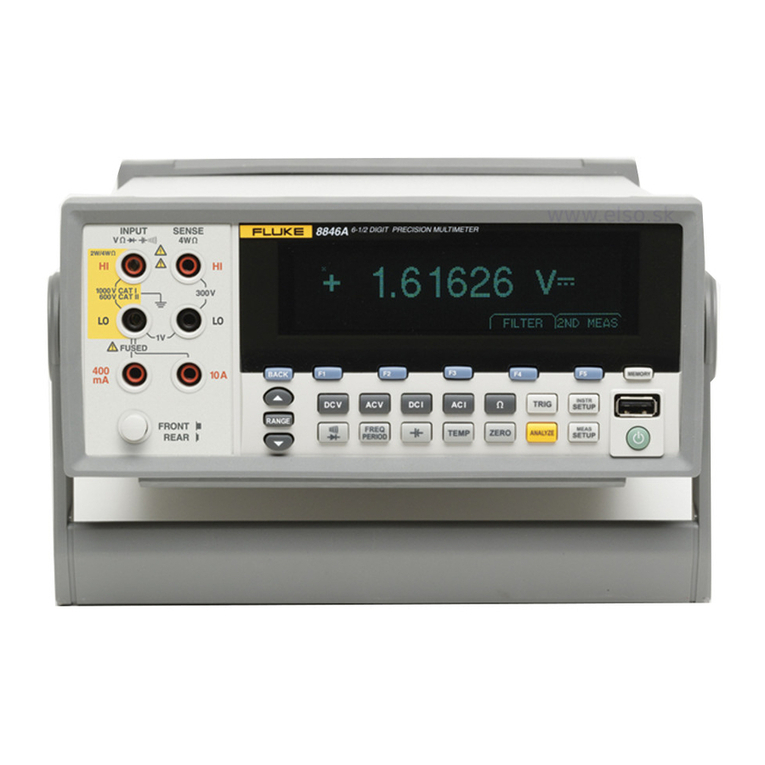
Fluke 8508A User manual

LIMITED WARRANTY AND LIMITATION OF LIABILITY
Each Fluke product is warranted to be free from defects in material and workmanship under normal use and
service. The warranty period is one year and begins on the date of shipment. Parts, product repairs, and
services are warranted for 90 days. This warranty extends only to the original buyer or end-user customer of
a Fluke authorized reseller, and does not apply to fuses, disposable batteries, or to any product which, in
Fluke's opinion, has been misused, altered, neglected, contaminated, or damaged by accident or abnormal
conditions of operation or handling. Fluke warrants that software will operate substantially in accordance
with its functional specifications for 90 days and that it has been properly recorded on non-defective media.
Fluke does not warrant that software will be error free or operate without interruption.
Fluke authorized resellers shall extend this warranty on new and unused products to end-user customers
only but have no authority to extend a greater or different warranty on behalf of Fluke. Warranty support is
available only if product is purchased through a Fluke authorized sales outlet or Buyer has paid the
applicable international price. Fluke reserves the right to invoice Buyer for importation costs of
repair/replacement parts when product purchased in one country is submitted for repair in another country.
Fluke's warranty obligation is limited, at Fluke's option, to refund of the purchase price, free of charge repair,
or replacement of a defective product which is returned to a Fluke authorized service center within the
warranty period.
To obtain warranty service, contact your nearest Fluke authorized service center to obtain return
authorization information, then send the product to that service center, with a description of the difficulty,
postage and insurance prepaid (FOB Destination). Fluke assumes no risk for damage in transit. Following
warranty repair, the product will be returned to Buyer, transportation prepaid (FOB Destination). If Fluke
determines that failure was caused by neglect, misuse, contamination, alteration, accident, or abnormal
condition of operation or handling, including overvoltage failures caused by use outside the product’s
specified rating, or normal wear and tear of mechanical components, Fluke will provide an estimate of repair
costs and obtain authorization before commencing the work. Following repair, the product will be returned to
the Buyer transportation prepaid and the Buyer will be billed for the repair and return transportation charges
(FOB Shipping Point).
THIS WARRANTY IS BUYER'S SOLE AND EXCLUSIVE REMEDY AND IS IN LIEU OF ALL OTHER
WARRANTIES, EXPRESS OR IMPLIED, INCLUDING BUT NOT LIMITED TO ANY IMPLIED WARRANTY
OF MERCHANTABILITY OR FITNESS FOR A PARTICULAR PURPOSE. FLUKE SHALL NOT BE LIABLE
FOR ANY SPECIAL, INDIRECT, INCIDENTAL, OR CONSEQUENTIAL DAMAGES OR LOSSES,
INCLUDING LOSS OF DATA, ARISING FROM ANY CAUSE OR THEORY.
Since some countries or states do not allow limitation of the term of an implied warranty, or exclusion or
limitation of incidental or consequential damages, the limitations and exclusions of this warranty may not
apply to every buyer. If any provision of this Warranty is held invalid or unenforceable by a court or other
decision-maker of competent jurisdiction, such holding will not affect the validity or enforceability of any other
provision.
Fluke Corporation
P.O. Box 9090
Everett, WA 98206-9090
U.S.A.
Fluke Europe B.V.
P.O. Box 1186
5602 BD Eindhoven
The Netherlands
11/99
To register your product online, visit register.fluke.com

Table of Contents
Chapter Title Page
1 Introduction and Safety Information.................................................. 1-1
Introduction........................................................................................................ 1-3
How to Contact Fluke ........................................................................................ 1-3
Unpacking and Inspection.................................................................................. 1-4
Standard Accessories..................................................................................... 1-4
Optional Accessories ..................................................................................... 1-5
Storing and Shipping the Multimeter................................................................. 1-6
Line Voltage ...................................................................................................... 1-6
Power Voltage Selector and Fuses ................................................................ 1-6
Changing Supply Voltage or Replacing Line Fuse ....................................... 1-6
Calibration Enable Switch ................................................................................. 1-7
System Use .................................................................................................... 1-7
Safety Considerations and Symbols................................................................... 1-7
General Safety Summary............................................................................... 1-7
Safety Information ............................................................................................. 1-8
Symbols ............................................................................................................. 1-10
Protection Class I........................................................................................... 1-11
Protective Earth/Ground............................................................................ 1-11
Do Not Operate Without Covers............................................................... 1-11
Safe Operating Conditions ........................................................................ 1-11
Fuse Requirements .................................................................................... 1-12
Rear Panel Detail....................................................................................... 1-12
The Power Cable and Power Supply Disconnection................................. 1-12
Terminal Connections ............................................................................... 1-13
Measurement Category I ............................................................................... 1-13
Maintenance and Repair ................................................................................ 1-13
Moving and Cleaning .................................................................................... 1-13
2 Getting Acquainted with the Basics .................................................. 2-1
Introduction........................................................................................................ 2-3
Input Terminals.................................................................................................. 2-3
The Front Panel Displays................................................................................... 2-4
Front Panel Keys................................................................................................ 2-4
Soft-Keys and Manual Conventions.............................................................. 2-4
Numeric Keyboard ........................................................................................ 2-5
i

8508A
Users Manual
Exiting a Menu .............................................................................................. 2-5
Major Function Keys..................................................................................... 2-5
Direct Action Keys ........................................................................................ 2-6
Mode Keys..................................................................................................... 2-6
Rear Panel .......................................................................................................... 2-7
Labels ............................................................................................................ 2-7
Fuses.............................................................................................................. 2-7
Voltage Selector ............................................................................................ 2-7
Power Input and Power Switch ..................................................................... 2-7
Calibration Switch ......................................................................................... 2-7
Rear Panel Connectors and Pin Designations.................................................... 2-8
Rear Inputs..................................................................................................... 2-8
External Trigger Input ................................................................................... 2-8
IEEE 488 Input/Output.................................................................................. 2-8
Power-On Configuration.................................................................................... 2-8
The 8508A-LEAD Measurement Lead Kit........................................................ 2-9
3 Making Measurements........................................................................ 3-1
Introduction........................................................................................................ 3-3
Making Connections to the Multimeter -- General Guidelines.......................... 3-4
Using the Measurement Functions..................................................................... 3-5
DC Voltage.................................................................................................... 3-5
Measuring DC Voltage.................................................................................. 3-7
Making Input Connections........................................................................ 3-7
AC Voltage.................................................................................................... 3-8
Measuring AC Voltage.................................................................................. 3-11
Induced Interference.................................................................................. 3-11
Common Mode Rejection ......................................................................... 3-11
Lead Considerations.................................................................................. 3-11
Resistance...................................................................................................... 3-11
High Voltage Ohms....................................................................................... 3-13
True Ohms..................................................................................................... 3-15
Measuring Resistance.................................................................................... 3-17
2-Wire Measurements ............................................................................... 3-17
4-wire Measurements ................................................................................ 3-17
4-wire High Resistance Measurements ..................................................... 3-18
4-wire Resistance Zero.............................................................................. 3-18
ΩGuard..................................................................................................... 3-19
DC Current .................................................................................................... 3-21
Measuring DC Current .................................................................................. 3-22
AC Current .................................................................................................... 3-23
Measuring AC Current .................................................................................. 3-24
Temperature................................................................................................... 3-25
Measuring Temperature................................................................................. 3-28
Multimeter Inputs .............................................................................................. 3-29
Input............................................................................................................... 3-29
Using the INPUT Key ................................................................................... 3-29
SCAN OPERATIONS................................................................................... 3-30
Tru Ohms Ratio......................................................................................... 3-31
Monitoring Modes ............................................................................................. 3-32
Monitor Key .................................................................................................. 3-32
Displaying Signal Frequency......................................................................... 3-32
Displaying Standard Deviation...................................................................... 3-32
Devn Menu................................................................................................ 3-32
ii

Contents (continued)
Displaying Maximum, Minimum, and Peak-to-Peak Readings .................... 3-33
MAX Menu ............................................................................................... 3-33
Limit-Checking ......................................................................................... 3-33
Monitor Menu Tree ....................................................................................... 3-34
Utility................................................................................................................. 3-34
Using the Selftest Functions .............................................................................. 3-37
Test Menu Tree.............................................................................................. 3-38
Test Key ........................................................................................................ 3-39
Using the Math Functions.................................................................................. 3-40
Math Functions and Menu Tree..................................................................... 3-40
Math Configuration ....................................................................................... 3-41
Clear Functions .................................................................................................. 3-42
4 Remote Operations Using the IEEE 488 Interface............................ 4-1
Introduction........................................................................................................ 4-3
Interface Capability: IEEE Standards 488.1 and 488.2 ..................................... 4-3
The Multimeter in IEEE 488.2 Terminology ................................................ 4-3
Programming Options ................................................................................... 4-3
Capability Codes ........................................................................................... 4-3
Interconnections................................................................................................. 4-4
Using the 8508A Reference Multimeter in a System ........................................ 4-5
Setting the Multimeter Address..................................................................... 4-5
Remote Operation General Considerations ................................................... 4-5
Syntax Diagrams in this Manual ................................................................... 4-5
The 8508A Status Reporting Structure.......................................................... 4-8
Types of Status Information Available.......................................................... 4-9
Syntax Diagrams of Major 8508A Functions .................................................... 4-10
DC Voltage.................................................................................................... 4-10
AC Voltage.................................................................................................... 4-11
Resistance: Normal OHMS ........................................................................... 4-13
Resistance: High Voltage OHMS.................................................................. 4-14
Resistance: True OHMS................................................................................ 4-15
DC Current .................................................................................................... 4-16
AC Current .................................................................................................... 4-17
Using Platinum Resistance Thermometers to obtain Temperature. .............. 4-18
Determine the PRT identity........................................................................... 4-18
Entering or Editing the Characteristics of a PRT to Non-volatile Store....... 4-19
Recalling the Characteristics of a Known PRT ............................................. 4-20
Deleting a Known PRT from the Non-volatile Store .................................... 4-20
Input............................................................................................................... 4-21
Guard ............................................................................................................. 4-21
Measurement Gate Width.............................................................................. 4-22
Maximum, Minimum and Peak-Peak............................................................ 4-22
Limits............................................................................................................. 4-24
Recall Limits ................................................................................................. 4-24
Enable Limits................................................................................................. 4-24
Standard Deviation ........................................................................................ 4-25
Syntax Diagrams of Math Functions ................................................................. 4-25
Averaging ...................................................................................................... 4-25
Multiplication ................................................................................................ 4-27
Subtraction..................................................................................................... 4-28
Division ......................................................................................................... 4-29
Decibel Calculations...................................................................................... 4-30
Syntax Diagram of Test ..................................................................................... 4-31
iii

8508A
Users Manual
Selftest ........................................................................................................... 4-31
Device Errors and Syntax Diagrams.................................................................. 4-31
Error Detection .............................................................................................. 4-31
Recall Device Errors...................................................................................... 4-32
Triggering and Reading Operations................................................................... 4-33
Trigger Source Selector................................................................................. 4-33
Execute Trigger ............................................................................................. 4-34
Execute Trigger and Take a Reading ............................................................ 4-34
Settling Delay ................................................................................................ 4-34
Input Zero ...................................................................................................... 4-36
Wait ............................................................................................................... 4-36
Reading Recall............................................................................................... 4-36
Access to the Internal Buffer Memory .......................................................... 4-37
Internal Operations Commands ......................................................................... 4-39
Reset .............................................................................................................. 4-39
Complete Operations ..................................................................................... 4-40
Status Reporting................................................................................................. 4-40
Instrument I/D and Setup................................................................................... 4-44
Calibration Commands and Messages ............................................................... 4-46
Calibration Sequences ................................................................................... 4-46
Protected User Data....................................................................................... 4-48
Special Calibrations....................................................................................... 4-49
5 Specifications ...................................................................................... 5-1
Specifications..................................................................................................... 5-3
General Specifications................................................................................... 5-3
Maximum Voltage and Current Inputs.......................................................... 5-4
DC and AC Voltage .................................................................................. 5-4
DC and AC Current................................................................................... 5-4
Resistance and Temperature ..................................................................... 5-4
Electrical Measurement Specifications.............................................................. 5-5
DC Current .................................................................................................... 5-6
AC Voltage.................................................................................................... 5-7
AC Current .................................................................................................... 5-9
Resistance...................................................................................................... 5-11
Temperature................................................................................................... 5-13
Read Rate and Additional Uncertainty.......................................................... 5-14
Applying the Specifications............................................................................... 5-15
Introduction ................................................................................................... 5-15
Absolute and Relative Specifications ............................................................ 5-15
Applying User’s Calibration Uncertainties ................................................... 5-16
Operating and Calibration Temperature Ranges ........................................... 5-16
Applying Temperature Coefficient Specifications ........................................ 5-16
Ratio Measurements ...................................................................................... 5-17
Additional Errors ........................................................................................... 5-17
6 Adjustment and Verification............................................................... 6-1
Introduction........................................................................................................ 6-3
Adjustment Overview ........................................................................................ 6-3
Adjustment Interval and Performance ............................................................... 6-3
Adjustment Points.............................................................................................. 6-3
Non-Nominal Values..................................................................................... 6-4
Enabling Access to Calibration Adjustment Mode............................................ 6-4
Calibration Menus.............................................................................................. 6-4
iv

Contents (continued)
Accessing the Calibration Menus and Calibration Mode .............................. 6-4
Calibration Menu........................................................................................... 6-5
SET VALUE Menu ....................................................................................... 6-5
SPOT CAL Menu .......................................................................................... 6-6
SPOT (1 to 6) RMS Menus ........................................................................... 6-6
SPOT FREQUENCY (1 to 6) Menu ............................................................. 6-7
Special Calibration ........................................................................................ 6-7
SPCL Menu ................................................................................................... 6-7
SER # Menu .................................................................................................. 6-8
Hvlin Menu.................................................................................................... 6-8
Non-volatile input offset compensation............................................................. 6-9
Routine Adjustment ........................................................................................... 6-9
Equipment Required for Adjustment............................................................. 6-10
Preparing for Adjustment .............................................................................. 6-11
Interconnections ............................................................................................ 6-12
ADC Adjustment ........................................................................................... 6-14
DC Voltage Adjustment ................................................................................ 6-14
AC Voltage Adjustment ................................................................................ 6-17
Resistance Adjustment .................................................................................. 6-19
AC Current Adjustment................................................................................. 6-30
Frequency Adjustment................................................................................... 6-32
Cal Due Date Entry ....................................................................................... 6-32
Non-Volatile Input Offset Adjustment.......................................................... 6-33
ACV Spot Frequency Adjustment ..................................................................... 6-34
Performance Verification................................................................................... 6-35
Equipment Requirements .............................................................................. 6-36
Interconnections ............................................................................................ 6-36
Applicable Verification Tolerance and Conditions ....................................... 6-36
Preparation..................................................................................................... 6-37
DC Voltage Checks ....................................................................................... 6-37
AC Voltage Checks ....................................................................................... 6-40
Resistance Checks ......................................................................................... 6-42
Normal ΩChecks .......................................................................................... 6-44
Normal LoI Ωchecks .................................................................................... 6-44
Tru Ω checks ................................................................................................. 6-44
Tru ΩLoI checks........................................................................................... 6-44
HiV Ωchecks ................................................................................................ 6-44
DC Current Checks........................................................................................ 6-46
AC Current Checks........................................................................................ 6-48
Frequency Checks ......................................................................................... 6-50
Appendices
A Error Codes and Message............................................................................ A-1
B Rack Mount Kit........................................................................................... B-1
C Rack Mount Slide Kit.................................................................................. C-1
v

8508A
Users Manual
vi

List of Tables
Table Title Page
1-1. Standard Accessories ............................................................................................. 1-4
1-2. Additional Accessories for the Multimeter ............................................................ 1-5
1-3. Power Input Fuse 1................................................................................................. 1-12
1-4. Current Function Rear Input Fuse 2....................................................................... 1-12
3-1. Identifying and Avoiding Errors ............................................................................ 3-4
3-1. Additional Accessories for the Multimeter ............................................................ 3-19
4-1. IEEE Interface Capability ...................................................................................... 4-4
4-2. Delay Defaults for DCV, DCI, ACV, and ACI...................................................... 4-35
4-3. Delay Defaults for Ohms, Tru Ohms, and Hi Ohms .............................................. 4-35
6-1. Required Equipment for Calibration and Performance Verification...................... 6-10
6-2. Calibration Sequence ............................................................................................. 6-12
6-3. DC Voltage Calibration Points and Sequence........................................................ 6-15
6-4. AC Voltage Calibration Points and Sequence........................................................ 6-18
6-5. Resistance Calibration Points and Sequence.......................................................... 6-20
6-6. DC Current Calibration Points and Sequence ........................................................ 6-29
6-7. AC Current Calibration Points and Sequence ........................................................ 6-31
6-8. DC Voltage Verification Points and Sequence ...................................................... 6-39
6-9. AC Voltage Verification Points and Sequence ...................................................... 6-41
6-10. Resistance Verification Points and Sequence ........................................................ 6-45
6-11. DC Current Verification Points and Sequence....................................................... 6-47
6-12. AC Current Verification Points and Sequence....................................................... 6-49
vii

8508A
Users Manual
viii

List of Figures
Figure Title Page
1-1. Rear Panel - Power Input Fuse and line Power Locations ..................................... 1-12
2-1. Front Panel Displays .............................................................................................. 2-3
2-2. Front and Rear Input Terminals ............................................................................. 2-3
2-3. Sample of the Main Display................................................................................... 2-4
2-4. 8508A Rear Panel Detail........................................................................................ 2-7
2-5. The 8508A-LEAD Measurement Lead Kit............................................................ 2-10
3-1. Simple Lead Connections ...................................................................................... 3-7
3-2. Twisted-Pair Cable Connections............................................................................ 3-7
3-3. External Guard Connections .................................................................................. 3-7
3-4. Internal Guard Connections ................................................................................... 3-8
3-5. 2-Wire Measurements ............................................................................................ 3-17
3-6. 4-Wire Measurements ............................................................................................ 3-18
3-7. 4-Wire High Resistance Measurements ................................................................. 3-18
3-8. Resistance Zero Measurements.............................................................................. 3-19
3-9. ΩGuard Measurements ......................................................................................... 3-20
3-10. Internal Guard Connections ................................................................................... 3-20
3-11. PRT Connections ................................................................................................... 3-28
3-12. TruΩRatio Measurements ..................................................................................... 3-31
4-1. IEEE 488 Input/Output Connector......................................................................... 4-4
4-2. 8508A Status Report Structure............................................................................... 4-8
6-1. Equipment Connections Required for Calibration ................................................. 6-13
ix

8508A
Users Manual
x

Chapter 1
Introduction and Safety Information
Title Page
Introduction........................................................................................................ 1-3
How to Contact Fluke ........................................................................................ 1-3
Unpacking and Inspection.................................................................................. 1-4
Standard Accessories..................................................................................... 1-4
Optional Accessories ..................................................................................... 1-5
Storing and Shipping the Multimeter................................................................. 1-6
Line Voltage ...................................................................................................... 1-6
Power Voltage Selector and Fuses ................................................................ 1-6
Changing Supply Voltage or Replacing Line Fuse ....................................... 1-6
Calibration Enable Switch ................................................................................. 1-7
System Use .................................................................................................... 1-7
Safety Considerations and Symbols................................................................... 1-7
General Safety Summary............................................................................... 1-7
Safety Information ............................................................................................. 1-8
Symbols ............................................................................................................. 1-10
Protection Class I........................................................................................... 1-11
Protective Earth/Ground............................................................................ 1-11
Do Not Operate Without Covers............................................................... 1-11
Safe Operating Conditions ........................................................................ 1-11
Fuse Requirements .................................................................................... 1-12
Rear Panel Detail....................................................................................... 1-12
The Power Cable and Power Supply Disconnection................................. 1-12
Terminal Connections ............................................................................... 1-13
Measurement Category I ............................................................................... 1-13
Maintenance and Repair ................................................................................ 1-13
Moving and Cleaning .................................................................................... 1-13
1-1

1
Introduction and Safety Information
Introduction
Introduction
The Fluke 8508A Reference Multimeter (hereafter "the Multimeter") is designed for the
most demanding measurement applications and provides extremely high measurement
precision in both stand-alone and systems applications.
Chapter 1 ‘Introduction and Safety Information’ provides unpacking, storage and
shipping instructions, line voltage, and safety information.
Chapter 2 ‘Getting Acquainted with the Basic” provides an introduction to the front panel
keys operation and rear panel connector details.
Chapter 3 provides detailed access information to the full range of multimeter facilities,
with suggestions for measurement techniques.
Chapter 4 provides detailed information for remote control access via the IEEE 488
interface.
Chapter 5 provides specification details for the multimeter.
Chapter 6 provides detailed information for access to calibration menus, suggested
calibration methods and verification of the multimeter.
Warning
To avoid electric shock, personal injury, or death, carefully read the
information under Safety Considerations before attempting to install,
use, or service the Multimeter.
How to Contact Fluke
To contact Fluke, call one of the following telephone numbers:
• Technical Support USA: 1-877-355-3225
• Calibration/Repair USA: 1-877-355-3225
• Canada: 1-800-36-FLUKE (1-800-363-5853)
• Europe: +31-40-2675-200
• Japan: +81-3-6714-3114
• Singapore: +65-6799-5566
• China: +86-400-810-3435
• Brazil: +55-11-3759-7600
• Anywhere in the world: +1-425-446-6110
To see product information and download the latest manual supplements, visit Fluke
Calibration’ s website at www.flukecal.com.
To register your product, visit http://flukecal.com/register-product.
1-3

8508A
Users Manual
Unpacking and Inspection
Every care is taken in the choice of packing material to ensure that your equipment will
reach you in perfect condition.
If the equipment has been subject to excessive handling in transit, the fact will probably
be visible as external damage to the shipping carton.
In the event of damage, the shipping container and cushioning material should be kept for
the carrier’s inspection.
Carefully unpack the equipment and check for external damage to the case, sockets etc. If
the shipping container and packing material are undamaged, they should be retained for
use in subsequent shipments. If damage is found notify the carrier and your sales
representative immediately.
For orders of the model 8508A/01 check that the instrument has the six terminals on the
rear panel for connection of signals.
Standard Accessories
The standard accessories supplied with the instrument are shown in Table 1-1. The type
of power cable supplied is determined at the time of ordering.
Table 1-2 lists additional accessories available for use with the Multimeter.
Table 1-1. Standard Accessories
Description Location Order Number
Power Cable
USA LC1 284174
UK LC4 769455
Europe LC3 769422
Swiss LC5 769448
India LC7 782771
China / Fiji / New Zealand LC6 658641
Brazil LC42 3841347
General Purpose Probe Kit and Wallet comprising:
2x Test Leads with 4mm Safety shroud plugs (Red and Black)
2x Test Probe (Red and Black)
2x Crocodile clips (Red and Black)
2x 4w Zero PCB
1903307
1907075
1908153
2463103
Users Manual 1673798
1-4

Introduction and Safety Information
Unpacking and Inspection 1
Optional Accessories
Table 1-2. Additional Accessories for the Multimeter
Description Order Number
Rack Mount Kit Y8508 1886215
Rack Mount Slide Kit Y8508S 1886232
Platinum Resistance Probe, Case and certificate.
R0 100 Ohms
Hart 5626-15-S
8508A – PRT 1886194
Standard Platinum Resistance Probe, Case and
certificate. R0 25.5 Ohms. Calibration by comparison
Hart 5699 1920-4-7
8508A – SPRT 1886182
Accredited UKAS calibration 1883673
Accredited NVLAP calibration 4022363
Calibration Kit comprising 1G Ohm standard, 2x 4 wire
Zero PCB and connecting lead for 5720A/5725
8508A-7000K 1886226
Mesurement Lead Kit and Wallet comprising:
4x Shielded leads with gold spades
1x High-current lead with gold spades
1x General Purpose Probe Kit (as above)
8508A – LEAD 1886203
Please note that accessories (except for Accredited Calibration) are generally shipped
separately, please refer to the Packing List supplied with your 8508A.
1-5

8508A
Users Manual
Storing and Shipping the Multimeter
The Multimeter should be stored under cover. The shipping container provides the most
suitable receptacle for storage, as it provides the necessary shock isolation for normal
handling operations.
Place the Multimeter inside a sealed bag. Place the bag into the cushioning material
inside the shipping container, and put the whole package in a location that complies with
the storage environment specification described in Chapter 5.
If the Multimeter is shipped, use the original shipping container if possible. It provides
shock isolation for normal handling operations. Any other container should provide
similar shock isolation to the following approximate internal packing dimensions (the
front terminals should be free):
Container Length Width Depth
Box 630 mm (25 in) 550 mm (22 in) 230 mm (9 in)
Cushioned 480 mm (19 in) 440 mm (17.3 in) 100 mm (4 in)
Place the instrument inside a sealed bag. Fit the bag into the cushioning material inside
the shipping container, and secure the whole package.
Line Voltage
Power Voltage Selector and Fuses
The instrument is packed ready for use with a line voltage determined at the time of
ordering.
8508A 115 or 8508A/01 115 For 100V to 120V supplies
8508A 240 or 8508A/01 240 For 200V to 240V supplies
Changing Supply Voltage or Replacing Line Fuse
The integrated POWER SWITCH, POWER INPUT plug contain the fuse drawer which
gives access to the line fuse and the line voltage selector.
Insert a small screwdriver blade in the narrow recess above the catch over the fuse drawer
to gain access to the fuse and the voltage selector.
To change from one voltage to the other, remove the voltage selector block and rotate
until the desired voltage faces outward. Refit the selector block and fit the corresponding
fuse. Check that the desired voltage is visible in the cutout of the fuse drawer.
For 200 V to 240 V supplies 230 is shown in the voltage selector window on the rear
panel.
For 100 V to 120 V supplies 115 is shown in the window.
Refer to Table 1-3 for full details of replacement Power Input fuse types.
1-6

1
Introduction and Safety Information
Calibration Enable Switch
This two-position switch on the rear panel protects the instrument calibration
memory.
The instrument was initially calibrated at the factory and the switch covered
with a calibration sticker, so the sticker and the switch should remain as
delivered, until immediate recalibration is intended.
If the calibration menu is selected while the calibration switch is not in the
enabled position, the menu is replaced by the warning message:
CALIBRATION DISABLED
System Use
The Multimeter is designed as standard to form part of a system, conforming to IEEE
488.2 Standard Digital Interface. The Device Documentation Requirements of this
standard are provided in Chapter 4.
Safety Considerations and Symbols
This sections addresses safety considerations and describes symbols that appear on the
Multimeter.
A Warning statement identifies conditions or practices that could result in injury or
death.
A Caution statement identifies conditions or practices that could result in damage to
the Multimeter or equipment to which it is connected.
Warning
This instrument can deliver a lethal electric shock.
To avoid electric shock, personal injury, or death, carefully read the
information under Safety Considerations before attempting to install,
use, or service the Multimeter.
General Safety Summary
This instrument has been designed and tested in accordance with the European standard
publication EN61010-1 : 2001 and U.S. / Canadian standard publications
UL 61010-1:2004 and CAN/CSA-C22.2 No.61010.1-04. The instrument has been
supplied in a safe condition.
This manual contains information and warnings that must be observed to keep the
instrument in a safe condition and ensure safe operation.
Using or servicing this Multimeter in conditions other than as specified in the Users
Manual could compromise your safety.
To use the use the Multimeter correctly and safely, read and adhere to the precautions on
the "Safety Page" and follow all the safety instructions or warnings given throughout this
manual that relate to specific measurement functions. In addition, follow all generally
accepted safety practices and procedures required when working with and around
electricity.
1-7

8508A
Users Manual
Safety Information
A Warning identifies conditions and procedures that are dangerous to the user.
Warning
To prevent possible electrical shock, fire, or personal injury:
• Read all safety information before you use the Product.
• Carefully read all instructions.
• Use the Product only as specified, or the protection supplied by
the Product can be compromised.
• Use extreme caution when the Product is in use. The Product can
supply a lethal electric shock.
• Do not use the Product if it operates incorrectly.
• Examine the Product before use. Do not use the Product if it
shows signs of damage. Carefully examine the insulation around
the connectors.
• Do not use the Product around explosive gas, vapor, or in damp
or wet environments.
• Do not use and disable the Product if it is damaged.
• Do not apply more than the rated voltage, between the terminals
or between each terminal and earth ground.
• Do not touch voltages >30 V ac rms, 42 V ac peak, or 60 V dc.
• Measure a known voltage first to make sure that the Product
operates correctly.
• Do not use test leads if they are damaged. Examine the test leads
for damaged insulation, exposed metal, or if the wear indicator
shows. Check test lead continuity.
• Use conductors of adequate gauge to make current
measurements. High current can cause excessive heating of
underrated conductors and can cause a fire.
• Use this Product indoors only.
• Use only the mains power cord and connector approved for the
voltage and plug configuration in your country and rated for the
Product.
• Make sure the ground conductor in the mains power cord is
connected to a protective earth ground. Disruption of the
protective earth could put voltage on the chassis that could cause
death.
• Replace the mains power cord if the insulation is damaged or if
the insulation shows signs of wear.
• If the mains power cord is to be the accessible disconnect device,
the mains power cord must not be longer than 3 meters
(118.1 inches).
• Remove all probes, test leads, and accessories that are not
necessary for the measurement.
• Do not remove the cover until the test leads are removed.
• Turn the Product off and remove the mains power cord. Stop for
two minutes to let the power assemblies discharge before you
open the fuse door.
• Do not operate the Product with covers removed or the case open.
Hazardous voltage exposure is possible.
1-8
Other manuals for 8508A
3
Table of contents
Other Fluke Multimeter manuals

Fluke
Fluke 805 User manual

Fluke
Fluke 21 User manual

Fluke
Fluke 112 User manual

Fluke
Fluke J 39200 User manual

Fluke
Fluke III Series User manual

Fluke
Fluke 287 Installation and operating instructions

Fluke
Fluke 83V User manual

Fluke
Fluke Series II User manual

Fluke
Fluke 113 Instruction manual

Fluke
Fluke 175 User manual

Fluke
Fluke LinkRunner Pro User manual

Fluke
Fluke 114 User manual

Fluke
Fluke 8060A User manual

Fluke
Fluke 77 Series IV User manual

Fluke
Fluke 279 FC User manual

Fluke
Fluke 175 Use and care manual

Fluke
Fluke 373 Use and care manual

Fluke
Fluke 91 Series II User manual

Fluke
Fluke 106 User manual

Fluke
Fluke 79 User manual