Hioki DT4252 User manual

EN
DIGITAL MULTIMETER
Instruction Manual
May 2015 Revised edition 2
DT4251A981-02 15-05H
DT4252
DT4253
DT4254
DT4255
DT4256
www.GlobalTestSupply.com
Find Quality Products Online at: sales@GlobalTestSupply.com

i
Contents
Introduction.........................................................................1
Verifying Package Contents ..............................................1
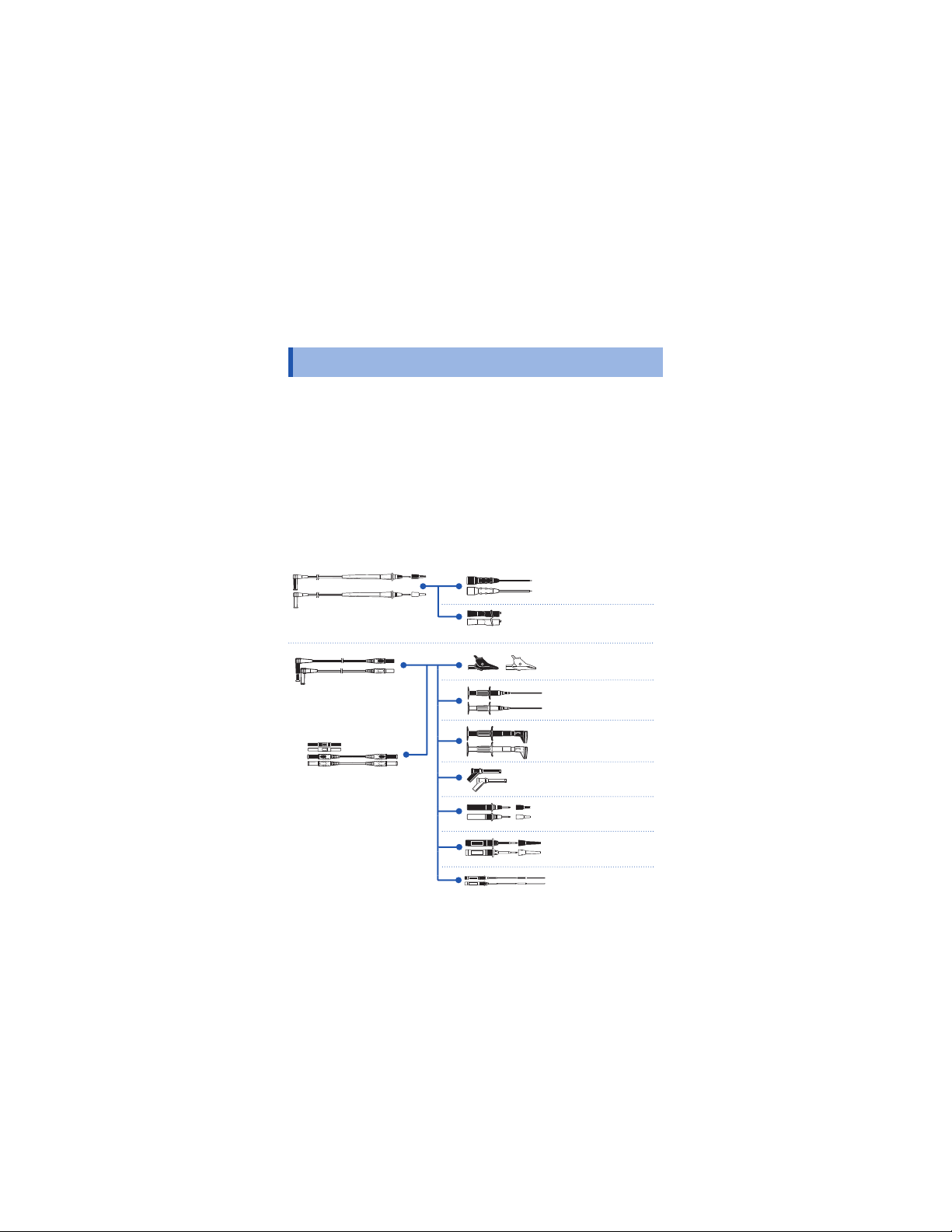
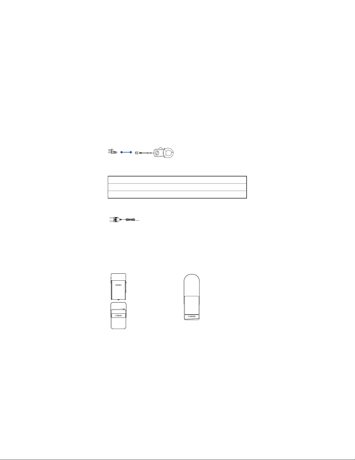
Options (sold separately) ..................................................2
Safety Notes........................................................................5
Usage Notes......................................................................10
1 Overview 15
1.1 Overview and Features.................................15
1.2 Parts Names and Functions.........................16
1.3 Display ...........................................................22
1.4 Alarm Display and Battery Indicator ...........23
2 Preparation for Measurements 25
2.1 Measurement Workflow................................25
2.2 Inserting/Replacing Batteries ...................... 26
2.3 Using Test Leads...........................................29
2.4 Installation in Measurement Location.........32
Using the instrument with the stand.......................... 32
Attaching the magnetic strap ....................................32
2.5 Using the Carrying Case ..............................34
3 Performing Measurements 37
3.1 Inspection Before Use ..................................37
3.2 Measuring Voltage.........................................43
Measuring AC voltage...............................................43
Measuring DC voltage ..............................................44
Measurement using the AC and DC automatic
judgment (DT4253DT4254DT4255DT4256).......45
3.3 Measuring Frequencies ................................46
DT4251A981-02
Ind.Appx.
7
6
5
4
3
2
1
www.GlobalTestSupply.com
Find Quality Products Online at: sales@GlobalTestSupply.com

ii
3.4 Checking Continuity
(DT4252DT4253DT4255DT4256).............47
3.5 Measuring Diode
(DT4252DT4253DT4255DT4256).............48
3.6 Measuring Resistance
(DT4252DT4253DT4255DT4256).............49
3.7 Measuring Temperatures (DT4253)..............50
3.8 Measuring Electrostatic Capacities
(DT4252DT4253DT4255DT4256).............52
3.9 Measuring Current
(DT4252DT4253DT4256)............................53
Measuring DC/AC Current........................................ 53
3.10 Measuring AC Current Using Clamp-on
Probe
(DT4253DT4255DT4256).................56
3.11 Checking the Electric Charge
(DT4254DT4255DT4256)............................58
4 Using Instrument Conveniently 59
4.1 Selecting the Measurement Range..............59
Measuring with the auto range .................................59
Measuring with the manual range............................. 59
4.2 Retaining the Measured Value .....................60
Retaining the measured value manually (HOLD) .....60
Automatically retaining the measured value
when the value stabilizes (AUTO HOLD)..................61
4.3 Reducing the Effect of the Noise (FILTER) . 64
4.4 Checking the Maximum/Minimum/Average 66
4.5 Checking the Relative Value/Performing
Zero Adjustment............................................ 67
Checking the relative value (REL) ............................67
Performing zero adjustment...................................... 69
www.GlobalTestSupply.com
Find Quality Products Online at: sales@GlobalTestSupply.com

iii
4.6 Turning On the Backlight..............................70
4.7 Using the Auto Power Save (APS)...............70
4.8 Using Plus/Minus Judgment Function
for Measurement Value
(DT4254DT4255DT4256)............................71
4.9 Communicating with PC...............................72
4.10 Power-on Option Table .................................74
Changing the temperature display unit ..................... 77
5 Specifications 79
5.1 General Specifications .................................79
5.2 Electrical Characteristics .............................81
5.3 Accuracy Table..............................................83
6 Maintenance and Service 95
6.1 RepairInspectionand Cleaning.................95
6.2 Troubleshooting ............................................ 96
6.3 Error Display..................................................99
6.4 Replacing Fuses..........................................100
Appendix Appx.1
Appx. 1 RMS and Average .............................Appx.1
Ind.Appx.
7
6
5
4
3
2
1
www.GlobalTestSupply.com
Find Quality Products Online at: sales@GlobalTestSupply.com

1
Introduction
Introduction
Thank you for purchasing the HIOKI DT4252, DT4253, DT4254,
DT4255, DT4256 Digital Multimeter. To obtain maximum
performance from the product, please read this manual first, and
keep it handy for future reference.
Verifying Package Contents
When you receive the instrument, inspect it carefully to ensure that
no damage occurred during shipping.
In particular, check the accessories, panel switches, and connectors.
If damage is evident, or if it fails to operate according to the
specifications, contact your authorized Hioki distributor or reseller.
Check the package contents as follows.
Instrument (The holster has been attached.)
DT4252
DT4253
DT4255
DT4254
DT4256
L9207-10 Test Lead
(p. 29)
LR03 Alkaline battery × 4
Instruction Manual
(English)
Instruction manuals
may also be available
in other languages.
1
Ind.Appx.
7
6
5
4
3
2
www.GlobalTestSupply.com
Find Quality Products Online at: sales@GlobalTestSupply.com

2
Options (sold separately)
The following options are available for the instrument. Contact your
authorized Hioki distributor or reseller when ordering.
Connecting cables
*6: AC33 V/DC70 V
*1: CATIV 600 V/CATIII 1000 V/CATII 1000 V
*2: CATIV 600 V/CATIII 1000 V
*3: CATIII 1000 V
*4: CATIII 600 V
*5: CATIII 300 V/CATII 600 V
*7: CATIII 600V/CATII 600V
L4938*7
Test Pin Set
L4939*4
Breaker Pin Set
L4933*6
Contact Pin Set
L4934*5
Small Alligator Clip Set
L4935*2
Alligator Clip Set
9243*3
Grabber Clip
L4936*4
Bus Bar Clip Set
L4937*3
Magnetic Adapter Set
L4932*1
Test Pin Set
L9207-10*1
Test Lead
L4930*2
Connection Cable Set
(Length: 1.2 m)
L4931*2
Extension Cable Set
(Length: 1.5 m, with the
coupling connector)
www.GlobalTestSupply.com
Find Quality Products Online at: sales@GlobalTestSupply.com

3
Options (sold separately)
For the clamp current measurement (Compatible only with the
DT4253, DT4255, and DT4256)
9010-50, 9018-50, 9132-50*4
Clamp-on Probe
9704
Conversion Adapter
Clamp-on probe Rated current Diameter of the measurable conductor
9010-50, 9018-50 500 Arms
46 mm or less
9132-50 1000 Arms
55 mm or less, 80×20 mm bus-bar
Temperature measurement (Only the DT4253)
DT4910 Thermocouples (K) (p. 50)
• Temperature measuring junction: Exposed type (welding)
• Sensor length: Approx. 800 mm
• Operating temperature: -40°C to 260°C (temperature
measuring part), -15°C to 55°C (connector)
• Allowable tolerance: ±2.5°C
Carrying Case
The instrument, test leads, instruction manual, and others can be stored in the
case.
C0201 Carrying Case
(p. 34)
3853 Carrying Case
C0202 Carrying Case
1
Ind.Appx.
7
6
5
4
3
2
www.GlobalTestSupply.com
Find Quality Products Online at: sales@GlobalTestSupply.com

4
Options (sold separately)
Z5004 Magnetic Strap (p. 32)
Attach this strap to the instrument and secure it on the
wall surface such as a metal plate for use.
DT4900-01 Communication Package (USB) (p. 72)
A communication adapter, USB cable, PC software,
and communication specifications are included.
The instrument data can be stored on the PC.
www.GlobalTestSupply.com
Find Quality Products Online at: sales@GlobalTestSupply.com

5
Safety Notes
Safety Notes
This instrument is designed to conform to IEC 61010 Safety
Standards, and has been thoroughly tested for safety prior to
shipment. However, using the instrument in a way not described in
this manual may negate the provided safety features.
Before using the instrument, be certain to carefully read the
following safety notes.
DANGER
Mishandling during use could result in injury or death,
as well as damage to the instrument. Be certain that
you understand the instructions and precautions in
the manual before use.
WARNING
With regard to the electricity supply, there are risks
of electric shock, heat generation, fire, and arc
discharge due to short circuits. If persons unfamiliar
with electricity measuring instruments are to use
the instrument, another person familiar with such
instruments must supervise operations.
Protective gear
WARNING
To avoid electric shock when measuring live lines,
wear appropriate protective gear, such as insulated
rubber gloves, boots and a safety helmet.
1
Ind.Appx.
7
6
5
4
3
2
www.GlobalTestSupply.com
Find Quality Products Online at: sales@GlobalTestSupply.com

6
Safety Notes
Notation
In this manual, the risk seriousness and the hazard levels are
classified as follows.
DANGER Indicates an imminently hazardous situation that will
result in death or serious injury to the operator.
WARNING Indicates a potentially hazardous situation that may
result in death or serious injury to the operator.
CAUTION
Indicates a potentially hazardous situation that may
result in minor or moderate injury to the operator or
damage to the instrument or malfunction.
IMPORTANT
Indicates information related to the operation of the
instrument or maintenance tasks with which the
operators must be fully familiar.
Indicates a high voltage hazard.
If a particular safety check is not performed or the
instrument is mishandled, this may give rise to a
hazardous situation; the operator may receive an
electric shock, may get burnt or may even be fatally
injured.
Indicates a strong magnetic-field hazard.
The effects of the magnetic force can cause
abnormal operation of heart pacemakers and/or
medical electronics.
Indicates prohibited actions.
Indicates the action which must be performed.
*Additional information is presented below.
www.GlobalTestSupply.com
Find Quality Products Online at: sales@GlobalTestSupply.com

7
Safety Notes
Symbols affixed to the instrument
Indicates cautions and hazards. When the symbol is printed on
the instrument, refer to a corresponding topic in the Instruction
Manual.
Indicates that dangerous voltage may be present at this terminal.
Indicates a double-insulated device.
Indicates a fuse.
Indicates a grounding terminal.
Indicates DC (Direct Current).
Indicates AC (Alternating Current).
Indicates DC (Direct Current) or AC (Alternating Current).
Symbols for various standards
Indicates the Waste Electrical and Electronic Equipment
Directive (WEEE Directive) in EU member states.
Indicates that the instrument conforms to regulations set out by
the EC Directive.
1
Ind.Appx.
7
6
5
4
3
2
www.GlobalTestSupply.com
Find Quality Products Online at: sales@GlobalTestSupply.com

8
Safety Notes
Screen display
This instrument uses the following screen displays.
1234567890
A BCDE FGH I J K LMNOPQR S TUVWX Y Z
A different display is used in the case below.
Appears when a broken Thermocouple (K) is detected. (p. 50)
Accuracy
We define measurement tolerances in terms of rdg. (reading) and
dgt. (digit) values, with the following meanings:
rdg.
(Reading or displayed value)
The value currently being measured and indicated on the
measuring instrument.
dgt.
(Resolution)
The smallest displayable unit on a digital measuring instrument,
i.e., the input value that causes the digital display to show a “1”
as the least significant digit.
www.GlobalTestSupply.com
Find Quality Products Online at: sales@GlobalTestSupply.com

9
Safety Notes
Measurement categories
To ensure safe operation of measuring instruments, IEC 61010
establishes safety standards for various electrical environments,
categorized as CAT II to CAT IV, and called measurement categories.
DANGER
•Using a measuring instrument in an environment
designated with a higher-numbered category than
that for which the instrument is rated could result in
a severe accident, and must be carefully avoided.
•Using a measuring instrument without categories in
an environment designated with the CAT II to CAT
IV category could result in a severe accident, and
must be carefully avoided.
This instrument conforms to the safety requirements for CAT III 1000 V, CAT
IV 600 V measuring instruments.
CAT II: When directly measuring the electrical outlet receptacles of
the primary electrical circuits in equipment connected to an
AC electrical outlet by a power cord (portable tools, household
appliances, etc.)
CAT III: When measuring the primary electrical circuits of heavy equipment
(fixed installations) connected directly to the distribution panel,
and feeders from the distribution panel to outlets
CAT IV: When measuring the circuit from the service drop to the service
entrance, and to the power meter and primary overcurrent
protection device (distribution panel)
T Outlet
CAT II
Internal wiring
Distribution panel
Service entrance
Service drop
CAT IV
Power meter
CAT III
Fixed installation
See: “2.3 Using Test Leads” (p. 29)
1
Ind.Appx.
7
6
5
4
3
2
www.GlobalTestSupply.com
Find Quality Products Online at: sales@GlobalTestSupply.com

10
Usage Notes
Usage Notes
Follow these precautions to ensure safe operation and to obtain the
full benefits of the various functions.
DANGER
If the test lead or the instrument is damaged, there is
a risk of electric shock. Before using the instrument,
perform the following inspection.
•Before using the instrument, check that the coating of
the test leads are neither ripped nor torn and that no
metal parts are exposed. Using the instrument under
such conditions could result in electrocution. Replace
the test leads with those specified by our company.
•Before using the instrument for the first time, verify that
it operates normally to ensure that no damage occurred
during storage or shipping. If you find any damage,
contact your authorized Hioki distributor or reseller.
Installation
Installing the instrument in inappropriate locations may cause a
malfunction of instrument or may give rise to an accident. Avoid the
following locations.
For details on the operating temperature and humidity, see the
specifications. (p. 79)
CAUTION
• Exposed to direct sunlight or high temperature
• Exposed to corrosive or combustible gases
• Exposed to water, oil, chemicals, or solvents
• Exposed to high humidity or condensation
• Exposed to a strong electromagnetic field or electrostatic
charge
• Exposed to high quantities of dust particles
• Near induction heating systems (such as high-frequency
induction heating systems and IH cooking equipment)
• Susceptible to vibration
www.GlobalTestSupply.com
Find Quality Products Online at: sales@GlobalTestSupply.com

11
Usage Notes
Handling the cables
WARNING
To prevent electric shock, when measuring the
voltage of a power line use a test lead that satisfies
the following criteria:
•Conforms to safety standards IEC61010 or EN61010
•Of measurement category III or IV
•Its rated voltage is higher than the voltage to be
measured
All of the optional test leads for this instrument
conform to the safety standard EN61010. Use a test
lead in accordance with its defined measurement
category and rated voltage.
CAUTION
• Avoid stepping on or pinching the cable, which could
damage the cable insulation.
• To avoid damaging the cables, do not bend or pull the
leads and the probe bases.
The ends of the test leads are sharp. Be careful to avoid injury.
For the test leads supplied with the instrument or the options to be connected
to the instrument, see the following information.
Accessories and options
Reference
Test lead “2.3 Using Test Leads” (p. 29)
Thermocouples (K) “3.7 Measuring Temperatures (DT4253)” (p. 50)
Clamp-on probe See the Instruction Manual which accompanies
the optional clamp.
USB cable “4.8 Communicating with PC” (p. 72)
Magnetic strap “2.4 Installation in Measurement Location”
(p. 32)
1
Ind.Appx.
7
6
5
4
3
2
www.GlobalTestSupply.com
Find Quality Products Online at: sales@GlobalTestSupply.com

12
Usage Notes
Precautions during measurement
WARNING
If the instrument is used in locations where the rating
indicated on the instrument or probes is exceeded,
the instrument may be damaged resulting in personal
injury. Do not use the instrument in such locations.
See “Measurement categories” (p. 9).
•With regard to the 10 A range, the maximum input
current is 10 A DC/10 Arms AC. Supplying a current
in excess of the maximum input may damage the
instrument and result in personal injury. Do not
supply current in excess of the specified limit. (Only
the DT4252 and DT4256)
Observe the following to avoid electric shock and/or
short circuits.
•Hazardous voltage may be generated in a free
measurement terminal. Do not touch the free
terminal.
•Use only test leads and optional equipment
specified by our company.
•Do not allow the metal part of the test lead to touch
any exposed metal, or to short between 2 lines.
Never touch the metal end.
•When connecting the clip-type test lead to the
active terminal, do not allow the lead to touch any
exposed metal, or to short between 2 lines.
•When the clamp-on probe is opened, do not allow
the metal part of the clamp to touch any exposed
metal, or to short between 2 lines, and do not
use over bare conductors. (For the clamp current
measurement, only the DT4253, DT4255, and
DT4256)
www.GlobalTestSupply.com
Find Quality Products Online at: sales@GlobalTestSupply.com

13
Usage Notes
CAUTION
• Do not input voltage or supply current exceeding the
specified measurement range. Doing so may damage
the instrument.
• During the continuity check, diode test, or measurement
of resistance or electrostatic capacity, measurement
signals are generated in the terminals of the instrument.
Depending on the target for measurement, the
measurement signal may cause damage.
See “Measurement current” and “Open circuit voltage”
in the “5.3 Accuracy Table” (p.83) in advance, that
there are no adverse effects of the measurement
current and the open circuit voltage.
Precautions during shipment
Observe the following during shipment. Hioki cannot be responsible
for damage that occurs during shipment.
CAUTION
• During shipment of the instrument, handle it carefully so
that it is not damaged due to a vibration or shock.
• To avoid damage to the instrument, remove the
accessories and optional equipment from the instrument
before shipment.
If the instrument is not to be used for an extended
period of time
IMPORTANT
To avoid corrosion and/or damage to the instrument due to battery
leakage, remove the batteries from the instrument if it is to be
kept in storage for an extended period.
1
Ind.Appx.
7
6
5
4
3
2
www.GlobalTestSupply.com
Find Quality Products Online at: sales@GlobalTestSupply.com

15
1Overview
1.1 Overview and Features
This measuring instrument is a multi-function digital multimeter that
ensures both safety and durability.
Main features and functions
• Speedy display of the RMS
measured value
• Environmental performance
(can be used anywhere)
• High noise-proof performance
• Filter function that controls the
influence of noise
• Display hold (HOLD)
For various purposes
The measurement test leads
and end pins can be selected.
Data transmission to
PC, control
The optional
DT4900-01
Communication
Package is required.
Large, easily-viewable
display
Backlighting to allow
users to read the
measurement values
in dark environments
Dual display
Two types of measured
values are displayed at the
same time.
Problem finding a suitable
installation location?
The strap with magnet allows the
instrument to be hung conveniently.
• Solid body which can be used for an
extended period of time (drop-proof)
• Maximum/minimum/average display
• Speedy measurement via a fast
response (0 V 100 V response
approx. 0.6 seconds*)
* Until the value falls within the
accuracy specification range.
If there is an excessive
input, a hazard is indicated
by the red LED.
www.GlobalTestSupply.com
Find Quality Products Online at: sales@GlobalTestSupply.com

16
Parts Names and Functions
1.2 Parts Names and Functions
Front
DT4252
DT4255 DT4256
DT4253
DT4254
Some indications are
different among the
models.
Display
(p. 22)
Operation
keys (p. 17)
Rotary
switch
(p. 18)
Measurement
terminals
(p. 20)
www.GlobalTestSupply.com
Find Quality Products Online at: sales@GlobalTestSupply.com

17
Parts Names and Functions
Operation keys
1
1
2
2
3
3
4
4
5
5
Normal Pressed down for
at least 1 second
Power-on
option (p. 74)
1
1
Manually sets/
cancels the hold
function for the
displayed value.
Sets/cancels the auto
hold function for the
displayed value.
Cancels the
auto power save
function (APS).
lights up/
goes off.
blinks/lights
up.
APS goes off.
2
2
Specifies/switches
the display of the
maximum, minimum,
and average values.
Cancels the display
of the maximum,
minimum, and average
values.
Sets/cancels
the plus/minus
judgment function.
/ / lights up/goes off.
3
3
Switches/cancels the
low pass filter and
passband settings.
Sets/cancels the
display of the relative
value (REL, T).
Turns off the
buzzer.
lights up/
goes off.
(T) lights up/
goes off.
4
4
Sets the manual
range/switches the
range, and sets the
clamp current range,
sets the sensitivity of
the electric charge
detection.
Cancels the manual
range.
All LCD’s light up
and the software
version and the
adjustment source
(factory or user)
are displayed.
RANGE: AUTO / RANGE: MANUAL
5
5
Turns on/off the
backlight.
- Turns off the
automatic backlight
deactivation.
www.GlobalTestSupply.com
Find Quality Products Online at: sales@GlobalTestSupply.com
Other manuals for DT4252
1
This manual suits for next models
4
Table of contents
Other Hioki Multimeter manuals

Hioki
Hioki DT4222 User manual

Hioki
Hioki DT4251 User manual

Hioki
Hioki 3801-50 User manual

Hioki
Hioki DT4221 User manual

Hioki
Hioki DT4252 User manual

Hioki
Hioki DT4281 User manual

Hioki
Hioki DT4280 Series User manual

Hioki
Hioki 3256-50 User manual

Hioki
Hioki 3255-50 HiTESTER User manual

Hioki
Hioki DT4221 User manual