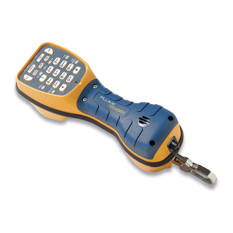
Fluke TS 1200 User manual

TS1200
ADSL/POTS Test Set
Users Guide
PN 2448927
October 2005
©2005 Fluke Corporation. All rights reserved. Printed in USA.
All product names are trademarks of their respective companies.
99 Washington Street
Melrose, MA 02176
Phone 781-665-1400
Toll Free 1-800-517-8431
Visit us at www.TestEquipmentDepot.com

LIMITED WARRANTY AND LIMITATION OF LIABILITY
Each Fluke Networks product is warranted to be free from defects in material and workmanship under
normal use and service. The warranty period for the mainframe is 18 months and begins on the date of
purchase. Parts, accessories, product repairs and services are warranted for 90 days, unless otherwise stated.
Ni-Cad, Ni-MH and Li-Ion batteries, cables or other peripherals are all considered parts or accessories. The
warranty extends only to the original buyer or end user customer of a Fluke Networks authorized reseller,
and does not apply to any product which, in Fluke Networks’ opinion, has been misused, abused, altered,
neglected, contaminated, or damaged by accident or abnormal conditions of operation or handling. Fluke
Networks warrants that software will operate substantially in accordance with its functional specifications
for 90 days and that it has been properly recorded on non-defective media. Fluke Networks does not warrant
that software will be error free or operate without interruption.
Fluke Networks authorized resellers shall extend this warranty on new and unused products to end-user
customers only but have no authority to extend a greater or different warranty on behalf of Fluke Networks.
Warranty support is available only if product is purchased through a Fluke Networks authorized sales outlet
or Buyer has paid the applicable international price. Fluke Networks reserves the right to invoice Buyer for
importation costs of repair/replacement parts when product purchased in one country is submitted for repair
in another country.
Fluke Networks warranty obligation is limited, at Fluke Networks option, to refund of the purchase price,
free of charge repair, or replacement of a defective product which is returned to a Fluke Networks
authorized service center within the warranty period.
To obtain warranty service, contact your nearest Fluke Networks authorized service center to obtain return
authorization information, then send the product to that service center, with a description of the difficulty,
postage and insurance prepaid (FOB destination). Fluke Networks assumes no risk for damage in transit.
Following warranty repair, the product will be returned to Buyer, transportation prepaid (FOB destination).
If Fluke Networks determines that failure was caused by neglect, misuse, contamination, alteration, accident
or abnormal condition of operation or handling, or normal wear and tear of mechanical components, Fluke
Networks will provide an estimate of repair costs and obtain authorization before commencing the work.
Following repair, the product will be returned to the Buyer transportation prepaid and the Buyer will be
billed for the repair and return transportation charges (FOB Shipping point).
THIS WARRANTY IS BUYER’S SOLE AND EXCLUSIVE REMEDY AND IS IN LIEU OF ALL OTHER WARRANTIES,
EXPRESS OR IMPLIED, INCLUDING BUT NOT LIMITED TO ANY IMPLIED WARRANTY OR MERCHANTABILITY OR
FITNESS FOR A PARTICULAR PURPOSE. FLUKE NETWORKS SHALL NOT BE LIABLE FOR ANY SPECIAL, INDIRECT,
INCIDENTAL OR CONSEQUENTIAL DAMAGES OR LOSSES, INCLUDING LOSS OF DATA, ARISING FROM ANY
CAUSE OR THEORY.
Since some countries or states do not allow limitation of the term of an implied warranty, or exclusion or
limitation of incidental or consequential damages, the limitations and exclusions of this warranty may not
apply to every buyer. If any provision of this Warranty is held invalid or unenforceable by a court or other
decision-maker of competent jurisdiction, such holding will not affect the validity or enforceability of any
other provision.
4/04-18
Fluke Networks
PO Box 777
Everett, WA 98206-0777
USA
i
Table of Contents
Chapter Title Page
1 Introduction
Description .............................................................................................................1-1
Unpacking ..............................................................................................................1-1
General Safety Information ..................................................................................1-2
Registration ............................................................................................................1-2
Contacting Fluke Networks ...................................................................................1-3
2 Operation
Keys .........................................................................................................................2-1
Icons ........................................................................................................................2-3
Connecting the TS1200 to an ADSL Line ..............................................................2-4
Using ADSL Mode ..................................................................................................2-5
Using POTS Mode ..................................................................................................2-8
POTS Mode Features ......................................................................................2-8
POTS Mode Operations ..................................................................................2-10
Configuring Your Test Set .....................................................................................2-13
POTS Configuration ........................................................................................2-13
System Configuration .....................................................................................2-15
ADSL Configuration ........................................................................................2-16
Downloading Stored Results to a PC ....................................................................2-17
Connecting to a PC .........................................................................................2-17
Setting Up the PC Port ...................................................................................2-17
Downloading Results ......................................................................................2-18
3 Maintenance and Specifications
Safety Information for Maintenance ....................................................................3-1
Cleaning .................................................................................................................3-1
Safety with Batteries .............................................................................................3-2
Charging the Batteries ..........................................................................................3-3
Replacing the Batteries .........................................................................................3-3
Replacing the Belt Clip ..........................................................................................3-5
Replacing the Line Cord ........................................................................................3-6
Accessories ..............................................................................................................3-8
Specifications .........................................................................................................3-8
4 Troubleshooting
Information Gathering ..........................................................................................4-1
Potential Failures at the Customer Premises ........................................................4-1

ii
TS1200 Test Set
Users Guide
Potential Failures in the Copper Loop ..................................................................4-3
Poor POTS Performance on an ADSL Line ............................................................4-3
Data Safe Practices .................................................................................................4-5

1-1
Chapter 1
Introduction
Description
The TS1200 ADSL/POTS Test Set is an analog test telephone used by installers, repair technicians,
and other authorized personnel for the testing of copper wire, voice subscriber, and ADSL lines.
The TS1200 can test ADSL lines for throughput, noise margin, and other parameters. It can
monitor ADSL and POTS lines simultaneously and can test ADSL service in either a snapshot or a
continuous mode.
The same circuitry that allows the TS1200 to test POTS services without downing ADSL also
prevents the test set from disrupting other types of digital data services (xDSL, ISDN) to which
the test set may have been unintentionally connected.
Unpacking
Provided in the TS1200 Test Set shipping box are the following items:
•
AC Adapter/Charger, 12 VDC, 10%, 600 mA
•
Batteries, NiMH, 1.2V (4)
•
Line Cord, RJ-45 to ABN
•
Modular Adapter, DB9/RJ11
•
Cable, RJ-11 to RJ-11, 7.0 ft
•
Vehicle Adapter
•
Users Guide

1-2
TS1200 Test Set
Users Guide
General Safety Information
Table 1-1 describes the international electrical symbols used on the Test Set and in this manual.
WXWarning
Good safety practices prohibit the connection of the TS1200 and
similar test sets to 117 VAC commercial electrical power. Should the
TS1200 Test Set be connected to commercial power, all warranties are
immediately voided.
When connecting to metallic network wires, handle alligator clips by
insulated boots.
Do not use the test set if it is damaged. Before you use the test set,
inspect the case. Look for cracks or missing plastic. Pay particular
attention to the insulation surrounding the connectors.
If this product is used in a manner not specified by the manufacturer,
the protection provided by the product may be impaired.
Registration
Registering your product with Fluke Networks gives you access to valuable information on
product updates, troubleshooting tips, and other support services. To register, fill out the online
registration form on the Fluke Networks website
Table 1-1. International Electrical Symbols
WWarning: Risk of personal injury. See the manual for details.
Caution: Risk of damage or destruction to equipment or software. See the manual for details.
XWarning: Risk of electric shock.
.Earth ground
)CAN/CSA-C22.2 No. 60950-1-03
CAN/CSA-C22.2 No. 1010.1-92 + CSA-C22.2 No. 1010.1B-97
UL/ANSI 3111-1
~Do not put products containing circuit boards into the garbage. Dispose of circuits boards in
accordance with local regulations.

1-4
TS1200 Test Set
Users Guide

2-1
Chapter 2
Operation
WXWarning
When connecting to metallic network wires, handle alligator clips by
insulated boots.
Keys
Table 2-1 describes the TS1200 Test Set keys. Figure 2-1 shows icons associated with some of the
keys.
Table 2-1. TS1200 Keys
Key Description
Power Allows the user to apply power to and remove power from the test set. The Power
key is recessed to avoid accidental power down. To turn the test set off, press and
hold the Power key. The test set automatically powers down after the user-selected
timeout period without activity.
Home The Home key offers the user a quick return to the Home menu. This allows the
user to select POTS or ADSL mode, and to set or check the system’s configuration.
Light Press the Light key to backlight the menu display (LCD) and the keypad for easier
viewing in dark areas. Press the Light key again to turn the backlight off. The
backlight turns off automatically if the keypad isn’t used for the user-selected
period.
POTS/ADSL The POTS/ADSL key allows the user to toggle between POTS and ADSL modes.
SPD Dial The TS1200 allows the storage of 10 speed dialing numbers in ten memory
locations (1 through 9 and zero). Each location will store up to 23 digits. If an
attempt is made to store more than 23 digits, only the first 23 are stored. The
number field is capable of displaying 19 digits. When more than 19 digits are
stored, the digits shift to the next row with each digit entered.
-continued-

2-2
TS1200 Test Set
Users Guide
Up/Down Arrow
Keys
The Up/Down arrow keys have two functions: to move the user through options
and to control the speaker volume.
In Speed Dial, Saving Reports, or Bits per Bin screens, the Up/Down arrow keys are
used to move the cursor through a list of options depending on the context on the
display.
In all other displays, pressing the Up/Down arrow keys toggles the sound level of
the test set’s active receiver between Normal and High volume. Changing volume
only affects the volume of received signals. It does not affect the volume of
transmitted signals.
Soft Function
Keys
The three soft function keys are located below the LCD and their function changes
depending on the context on the display. The three soft keys are labeled F1, F2,
and F3.
Speaker The Speaker key is labeled SPKR. Pressing the Speaker Key allows the user to turn
the speakerphone on or off.
Note
The transmitter is muted when the speaker is on.
Pause/Mute The Pause/Mute key is a dual function key which can be used to mute the
microphone or insert a pause (comma) into speed dialing numbers.
The Pause feature allows the user to insert a pause (comma) into speed dialing
numbers. This is required when dialing out through a system that provides a
second dial tone (e.g., PBX). To obtain a pause (comma), press and release the
Pause/Mute key.
To mute the microphone (handset or speaker), press and hold the Pause/Mute key
for one second or more.
Numeric Keypad The numeric keypad is used to dial telephone numbers and make menu selections.
The numeric keypad includes 12 standard dialing keys including the asterisk (∗)
and pound (#) keys.
Table 2-1. TS1200 Keys (continued)
Key Description
Test Equipment Depot - 800.517.8431 - 99 Washington Street Melrose, MA 02176
FAX 781.665.0780 - TestEquipmentDepot.com

2-3
Icons
Icons
Figure 2-1 shows the icons used on the TS1200 Test Set screens, and Table 2-2 describes the icons.
bdx01.eps
Figure 2-1. TS1200 Test Set Icons
Table 2-2. Icon Descriptions
Icon Description
Polarity When the test set is connected to a line with DC voltage, one of the two Polarity icons
indicates the DC polarity of the line. The plus (+) icon indicates the red test lead is
connected to the Ring (negative) side of the line and the black test lead is connected
to the Tip (positive) side of the line. The minus (-) icon indicates the test leads are
reversed; that is, with the red test lead connected to the Tip (positive) side and with
the black test lead connected to the Ring (negative) side. Nothing is shown when the
leads are disconnected or the line is not powered.
Battery Battery icons indicate the battery status. The lowest battery level icon is accompanied
by a short beeping sound. When this battery icon appears, you have approximately
15-20 seconds of operating time left before the test set automatically powers off.
Refer to Chapter 3 for more information on the low battery condition.
Battery full The charging screen is displayed when batteries are being charged (4 to 5 hours to
charge when batteries are completely dead). When charging is complete, the full
charge icon (F) is displayed in the upper right-hand corner of the LCD display.
-continued-

2-4
TS1200 Test Set
Users Guide
Connecting the TS1200 to an ADSL Line
Figure 2-2 shows a typical ADSL over POTS connection from a Central Office (CO) to the
customer’s premises. A TS1200 in Monitor mode may be connected to the Tip and Ring pair, at
any point in the connection, without interfering with the services on the line while ADSL tests
are not running.
The TS1200 may be used in Talk mode at locations on the line carrying only voice or voice and
data. Attempting to put the TS1200 in Talk mode on the portion of the line carrying voice and
data will result in a data lockout. The test set will not go off hook until the data lockout is
overridden (See POTS Mode Features).
The ADSL test functions in the TS1200 may be used at locations on the line carrying only data or
voice and data. However, the TS1200 ADSL tests will not run properly if the ATU-R is active.
Running the ADSL tests while the ATU-R is active may cause it to loose synchronization.
Notes
Running the ADSL tests in the middle of a line may result in low data rates or
no showtime, depending upon the length and condition of the line
between the TS1200 and the customer’s premises. Open the line between
the TS1200 and the customer’s premises to improve the ADSL connection.
Data rates obtained in the middle of a line will not be the same as data rates
obtained at the customer’s premises.
Achieving showtime in the middle of a line does not guarantee that
showtime can be achieved at the customer’s premises.
Speaker A speaker icon appears when the Speaker is on.
On/Off Hook The test set displays a telephone in the upper left-hand corner of the LCD screen that
indicates when the test set is on or off hook.
Volume Normal volume is represented by two parallel lines on the LCD screen. High volume is
represented by three parallel lines.
Mute Mute is represented by an M in the upper left-hand corner of the LCD screen.
Tone/Pulse Tone is represented by a musical note at the top of the LCD screen. Pulse is
represented by a square wave at the top of the LCD screen.
Table 2-2. Icon Descriptions (continued)
Icon Description

2-5
Using ADSL Mode
bdx02.eps
Figure 2-2. Line with Both ADSL and POTS
Using ADSL Mode
The TS1200 performs either Auto or Manual ADSL tests.
In ADSL mode, the user can maintain an active POTS call.
To enter ADLS mode, press 2on the Home Screen (the first screen displayed upon powering up
the unit) or press the POTS/ADSL key.
Note
Pressing the Home key at any screen will return you to the Home screen.
Change ADSL Mode 1 Press F2 - MODE.
2Press either 1 - Multi-Mode or 2 - G.LITE.
Auto Test Auto test allows the user to take a snapshot of the ADSL line status at a
particular time. Once data is collected, the test is terminated and results are
displayed.
To start Auto test, press F1 - Auto. The screen indicates that test set is
attempting a connection.
To stop Auto test, press F2 - Discon.
-continued-

2-6
TS1200 Test Set
Users Guide
Auto Test Showtime Once a connection is made and the test is complete, the ADSL test results are
shown on the screen. The user can scroll through the test data using the Up/
Down arrow keys. The user may also transition to screens displaying either
Bits Per Bin Graphs or Alarm Status.
Manual Test Manual test allows the user to test the ADSL service until manually
terminated. The results are continuously updated and displayed until the user
terminates the test.
To start Manual test, press F3 - Manual. The screen indicates that the test set is
attempting a connection.
To stop Manual test, press F2 - Discon.
Manual Test
Showtime
Once a connection is made and the results have been collected, the data is
shown on the screen. There is an activity counter that is an elapsed time
counter. The maximum time allowed for the elapsed counter is 99:59. The user
can:
1Scroll through the test data using the Up/Down arrow keys.
2Make a selection from the Showtime Display screen to transition to
screens displaying Bits Per Bin Graphs or Alarm Status.
Auto and Manual
ADSL Test Results
The following obtained upstream and downstream results are shown on both
the Showtime Display screens for Manual Test and Auto Test:
MaxB/R (Maximum Bit Rate): Displays the maximum attainable bit rate.
Results are presented in kbits/s. The measured values for upstream and
downstream should be greater than or equal to the minimum bit rate set in
the ATU-C.
B/Rate (Bit Rate): Displays the achieved Fast bit rate data path. Results are
presented in kbits/s. The measured values for upstream and downstream
should be greater than or equal to the minimum bit rate set in the ATU-C. The
result may be 0 if the Interleaved data path has been enabled by the ATU-C
Capac: Displays the capacity of the line as a ratio of achieved bit rate (B/Rate
or IntB/R) over the maximum attainable bit rate. Results are presented as a
percentage (%). A lower capacity reading generally implies greater noise
immunity.
IntB/R (Interleaved Bit Rate): Displays the achieved interleaved bit rate. Results
are presented in kbits/s. The measured values for upstream and downstream
should be greater than the minimum bit rate set in the ATU-C. The result may
be 0 if the Fast data path is turned on in the ATU-C.
NseMar (Noise Margin): Displays the realized noise margin. This is the amount
of increased noise relative to the measured noise power that the system
would be able to tolerate to maintain a bit error rate less than 10-7. Results are
presented in dB. The industry standard is for a minimum value of 6 dB.
-continued-

2-7
Using ADSL Mode
Auto and Manual
ADSL Test Results
(continued)
Out Pwr (Output Power): Displays the aggregate power which is a measure of
total output power. Results are presented in dBm. Typically the power output
is the minimum required to achieve the noise margin that the ATU-C had
been configured for.
Atten (Attenuation): Displays the total attenuation. The attenuation is the
measured difference in dB between the power transmitted at the near end
and received at the far end. Any value reported by the TS1200 that is greater
than 31 dB should be interpreted as 31 dB or higher.
Alarm Status The Alarm Display provides information on loss of signal (LOS), loss of frame
(LOF), loss of power (LOP), and loss of margin (LOM). Information is provided
for both Near and Far end of the line, if available. Alarm status can be viewed
from either Auto or Manual Test. The user can also clear all alarms.
To access the Alarm Status display press F1 - Alarm.
To clear an active alarm, press the F1 - Clear.
To return to the previous screen, press F3 - Prev.
Bits Per Bin Graph A Bits Per Bin Plot is displayed. The user can scroll through the plot using the
Up/Down arrow keys. A bin cursor is provided at the bottom of the display
screen. The Bits Per Bin Graph can be selected from either Auto or Manual
Showtime screens.
Each bin represents a 4.1 KHz frequency range and may be used to transfer up
to 15 bits in a single direction. Bins 0 through 6 separate ADSL from the POTS
band and carry no data. Bins 7 through 31 carry upstream data. Bins 32
through 37 separate the upstream and down-stream data. Bins 38 through
255 may carry downstream data.
To display a data graph from the Showtime Test Results screen, press F2 -
Graph. The graph is displayed.
To indicate the desired Bin, press F1 - < and move the screen to the left or
press F3 - > and move the screen to the right. The cursor will move below the
graph.
To pan to the right, press the Up arrow key for full page. To pan to the left,
press the Down arrow key for full page.
To return to the previous screen, press F2 - Prev.
-continued-

2-8
TS1200 Test Set
Users Guide
Using POTS Mode
Note
Pressing the Home key at any screen returns you to the Home screen.
POTS mode can be entered by selecting 1on the Home Screen (the first screen displayed upon
powering up the unit) or by pressing the POTS/ADSL key.
POTS Mode Features
Monitor Mode
Monitor mode is for audio monitoring of the Tip and Ring pair while on hook. In Monitor mode,
the test set has a high input impedance, which allows monitoring of the line without disrupting
conversations or data signaling if present. The test set draws no direct current from the line and
it transmits no signals to the line.
In the Monitor mode, the test set is typically used to perform one or more of the following
procedures:
•
Verification that a line is idle when looking for a line to borrow
•
Listening for noise on the line
•
Hunting for tracer tones
•
Performing a test for the presence of high frequency data on the line
Saving Test Results The user can save the test results or print out the results. Save Results can be
selected from either Auto or Manual Test.
To save or print the results:
1From the Showtime Test Results screen, press F3 - Exit.
2Press F1 - Yes.
3Press F2 - Edit.
4Move cursor to either Name or Number using Up/Down arrow keys.
5Make entry and press F1 - Save. The results are automatically saved.
See “Downloading Stored Results to a PC” for instructions on sending stored
results to a PC.

2-9
Using POTS Mode
WCaution
When testing circuits that are close to a battery source, the pops in the
handset receiver that result from clipping onto a line may be quite
loud. Although there is protection against acoustic shock built into the
test set, if the receiver is held tightly against the ear, acoustical shock
may occur. The TS1200 Test Set is designed to rest comfortably on the
shoulder with the receiver away from the ear. It should be used in this
position when working close to a battery source.
Talk Mode
When switched to Talk mode, the TS1200 goes off hook and draws dial tone. When off hook,
the test set operates like a standard telephone; it is typically used to verify the proper operation
of a voice telephone line or to establish temporary communications on a “borrowed pair”.
Data Lockout
During the transition between Monitor and Talk modes, a sub-mode may be entered if data is
present on the line. This sub-mode is referred to as Data Lockout mode. In the Data Lockout
mode, the unit is kept on hook, or locked out, despite having been switched to Talk mode. Data
Lockout mode is provided to help prevent accidental corruption of a data transmission while
working on the lines. The lockout may be overridden and the test set taken off hook, despite
the presence of data, if the user desires to.
Note
When the TS1200 ADSL modem is active, data lockout will not occur.
Data Lockout Override
The following are scenarios where the operator may wish to override a data lockout:
•
When there is false data detection due to RF pickup on a line that is near an AM radio
broadcast antenna. The RF induced in the line may appear to be data.
•
When accessing POTS on a subscriber line that carries both ADSL and POTS.
Telephone lines near AM radio broadcast facilities, pick up the RF signals from the broadcast
antennas. Normally this isn’t a problem for the TS1200. If the line is well balanced, the TS1200
will not see the RF signal because it is a common mode (longitudinal) signal. But if the line isn’t
well balanced, a portion of the RF signal will be converted to a differential (metallic) signal. If
the signal amplitude is high enough, it may be detected as high-speed data by the TS1200. If you
know for sure you are on such a line, use the unit’s override capability to go off hook.
Note
Lockout override can be activated only when the test set is locked out.

2-10
TS1200 Test Set
Users Guide
To activate data lockout override, press F1 - Ovride from the Data Lockout screen. If DC voltage is
present on the line, the test set stops alarming and goes off hook, allowing the user to perform
normal Talk mode functions.
To go back on hook, select F2 - Hangup. This puts the test set back in Monitor mode. The override
must be manually reactivated each time the user wants to take a locked-out test set off hook.
WCaution
Shorting the Tip and Ring leads together while connected to a data
line causes disruption to the data.
POTS Mode Operations
Making a call on the
POTS portion of the line
You can make calls on lines that have ADSL as well as those that do not. You
can also make calls while simultaneously testing the ADSL portion of a line.
Use the POTS/ADSL key to toggle between POTS and ADSL.
Originating a Call To originate a call:
1Clip the test set to Tip and Ring of a powered subscriber loop.
2Monitor (listen to) the line to verify it is idle.
3If not idle, disconnect the test set from the line.
4If idle, go to the POTS screen.
5Press F2 - Talk. The test set automatically tests for high-speed data and
talk battery on the line.
6If data is detected, the test set will not go off hook (will lockout) and will
beep indicating the presence of data. Try another line, or if you are sure
the data detection is false, you can override the data lockout (see Data
Lockout Override).
7If no data is detected, the test set will go off hook.
8The numeric keypad, LNR (F3), or SPD Dial may be used to dial a number
for originating a call.
To disconnect a call, press F2 - Hangup.
-continued-

2-11
Using POTS Mode
Answering a Call To answer an incoming call:
1If a ringing signal is received, go to the POTS screen and press
F2 - Talk. The test set automatically tests for high-speed data on the line.
2If no data is detected, the test set will go off hook.
3If data is detected, the test set will lock out and alarm.
4To go off hook with data present (this would most likely be an ADSL
line), press F1 - Ovride.
To disconnect a call, press F2 - Hangup.
Speed Dial To use speed dial:
1Press SPD Dial key.
2Highlight desired location with Up/Down arrow keys or number keys.
3Press F1 - Dial. The test set will go off hook and dial the selected number.
Note
Pressing and holding F3 - ERASE will erase the speed dial
entry.
To edit an existing stored number:
1Select number to be edited with Up/Down arrow keys or number keys.
2Press F2 - Edit.
3Move cursor to either Name or Number using Up/Down arrow keys.
4Press F2 - Bkspce. Cursor moves backward to delete existing information.
Note
For alphanumeric entry, use the standard phone keypad.
Q and Z are assigned to the 0 key, and a SPACE key
assigned to the asterisk (∗) key. To select between the 3
letters of a key, the user presses the key multiple times
(e.g., to obtain a C, the 2 key is pressed three times).
5After the entry is complete, press F1 - Save.
Note
Speed Dial numbers DO NOT automatically go into LNR
memory. For example, you call someone who is not in
speed dial, hang up, and call someone using speed dial.
When you hang up again and press LNR you will dial the
first person who was not in speed dial.
-continued-

2-12
TS1200 Test Set
Users Guide
Speed Dial (continued) To store a new speed dial number:
1Select an empty number using Up/Down arrow keys or number keys.
2Press F2 - Edit.
3Enter the name in the NAME field and the telephone number in the
NUMBER field.
Note
For alphanumeric entry, use the standard phone keypad.
Q and Z are assigned to the 0 key, and a SPACE key
assigned to the asterisk (∗) key. To select between the 3
letters of a key, the user presses the key multiple times
(e.g., to obtain a C, the 2 key is pressed three times).
After the entry is complete, press F1 - Save.
Hook/Flash When the test set is in Talk mode, press F1 - Flash. A timed interruption of the
loop current occurs. Hook flashing is commonly used for call waiting
functions on residential lines. Some PBX setups or telephone office switches
may use this signal to put a call on hold or to activate some special function.
One flash is indicated for each press of F1. The default hook flash duration is
600 ms. Holding F1 does not repeatedly flash the switch hook.
Last Number Redial Press F3 - LNR (Last Number Redialed), while in Talk mode. The last number
dialed is displayed on the screen as it is dialed. The last number dialed may be
recalled even after powering down the unit. The redial memory has a 23-
digit capacity. LNR is not available once off hook dialing has begun.
Note
Speed Dial numbers DO NOT automatically go into LNR
memory. For example, you call someone who is not in
speed dial, hang up, and call someone using speed dial.
When you hang up again and press LNR you will dial the
first person who was not in speed dial.
Load Coil (Optional) Allows the user to detect unwanted or misplaced loads. To activate load coil
detection:
1At the Home screen, press 1 - POTS.
2Press F3 - LdCoil. One of the following messages is displayed:
•
Load Coil Not Found
•
Load Coil Found
•
Noise/Data on Line
3If the Load Coil detecting line cord is not installed, the following
message is displayed: Detector Not Found.
Test Equipment Depot - 800.517.8431 - 99 Washington Street Melrose, MA 02176
FAX 781.665.0780 - TestEquipmentDepot.com
Table of contents
Other Fluke Test Equipment manuals

Fluke
Fluke ScopeMeter 190-104 Instruction manual

Fluke
Fluke 714 User manual

Fluke
Fluke 6109A User manual

Fluke
Fluke ScopeMeter 196 User manual

Fluke
Fluke P5515-V User manual

Fluke
Fluke 6135A/PMU User manual

Fluke
Fluke 712B Use and care manual

Fluke
Fluke 719PRO User manual

Fluke
Fluke 5320A User manual

Fluke
Fluke 719PRO User manual

Fluke
Fluke P3100 Series User manual

Fluke
Fluke 990DSL User manual

Fluke
Fluke 700PA3 User manual

Fluke
Fluke T50 User manual

Fluke
Fluke T5-600 User manual

Fluke
Fluke 717-1000G Instruction manual

Fluke
Fluke 5730A User manual

Fluke
Fluke i400s User manual

Fluke
Fluke 190-502/AM User manual

Fluke
Fluke ScopeMeter 190-502 User manual