7
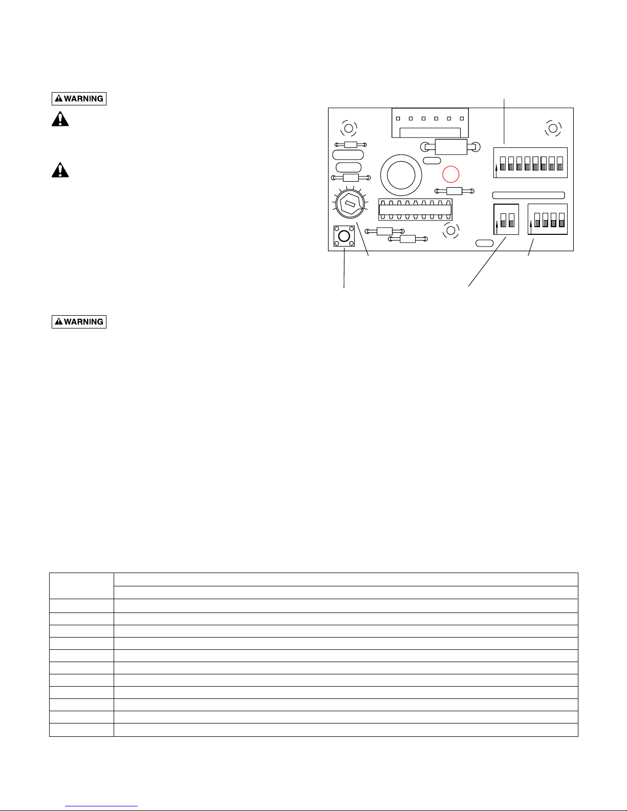
Pump Speed Adjustment
The pump speed potentiometer allows for speed adjust-
ment. The pump is factory set with the knob turned as far
as it will go clockwise ( ) for maximum speed (60
RPM). Adjust the interval and duration settings, rather than
the pump speed setting, to meet daily requirements. If you
need a slower pump speed after setting the interval and du-
ration switches, then turn the Pump Speed Adjustment
knob counter-clockwise as necessary to slow the pump.
NOTE: The rate of 6 fluid ounces per minute is based on 60
RPM. Any other speed setting will alter flow calculations.
MAINTENANCE
1. If flow decreases noticeably, check pump tubes for de-
terioration. Check the pump calibration whenever you
replace a pump tube.
2. Replace all pump tubes every six months. Check the
pump calibration whenever you replace a pump tube.
See “Calibration”, Page 6, for calibration instructions.
3. The pump is shipped from the factory with the pump
tubes pre-lubricated with silicone base grease.
Replacement pump tubes come with a packet of lubri-
cant and instructions for replacement and lubrication.
•No additional lubrication should be necessary if
tubes are replaced at 6-month intervals.
•If lubrication should become necessary, use a good
grade of silicone-based grease. DO NOT lubricate
the pump tube with any petroleum-based lubricants -
they will attack the pump tubes.
•Use only original equipment replacement parts for
these pumps. Use of pump tubes other than factory
authorized replacements may cause leakage, chemi-
cal burns, and property damage.
Replacing Pump Tube
Periodic replacement of the pump tube should be made to
avoid unscheduled service calls. To replace or inspect a
pump tube, follow the procedure below.
1. Turn off input power to the dispenser.
2. Remove chemical supply and injection tubing from the
pump.
3. Remove the lower left and upper right 1-5/8” screws
from pump cover to remove the pump from the
dispenser.
4. Remove the remaining two screws from the pump
cover and snap cover off pump housing by grasping
the extended lip of cover on lower edge.
5. Remove pump rotor assembly. DO NOT grasp the
springs.
6. Remove pump tube from pump housing by working
the tube stems out of the pump housing.
7. Install the new tube, making sure to lock tube stems
into pump housing tube stem collars. DO NOT twist
the tube when installing.
8. Lubricate the housing hole and the cover hole for the
rotor assembly shaft, and wherever rollers touch the
pump tube, using silicone-based grease.
9. Install rotor assembly by pressing roller against tubing
at the top of the pump housing.
10. Seat rotor shaft in pump housing hole.
11. Snap pump cover onto rotor and housing and install
upper left and lower right 1-1/4” cover screws. (DO
NOT overtighten.)
12. Using a large blade screwdriver, turn rotor assembly to
see that pump is assembled correctly and operating
properly.
13. Place pump on dispenser motor shaft so that motor
shaft mates with pump rotor. Rotate pump (NOT
motor shaft) so that upper right and lower left pump
cover holes align with holes in dispenser.
14. Install pump mounting screws to attach pump to dis-
penser (DO NOT overtighten pump mounting screws.)
15. Reinstall chemical supply and injection tubing to the
pump.