FMS FMS-cradleGUARD Specification sheet

FMS-cradleGUARDTM
Operating Manual and Installation Instructions
Wireless Signal Transmission
from Cradle to Control Station
Document Version 2.10
Published / Author 07/2019 / NS
Diese Bedienungsanleitung ist auch in Deutsch erhältlich.
Bitte nehmen Sie mit der nächstgelegenen FMS Niederlassung Kontakt auf.
© by FMS Force Measuring Systems AG, CH-8154 Oberglatt – All rights reserved.

FMS-cradleGUARD Operating Manual and Installation Instructions
24.07.2019 2
1 Content
1 CONTENT ............................................................................................................................................................. 2
2 SAFETY INFORMATION ...................................................................................................................................... 3
2.1 Presentation of Safety Information ............................................................................................................... 3
2.1.1 Danger that Could Result in Minor or Moderate Injuries .......................................................................... 3
2.1.2 Note Regarding Proper Function ............................................................................................................. 3
2.2 General Safety Information .......................................................................................................................... 3
3 PRODUCT INFORMATION .................................................................................................................................. 5
3.1 Functional Description .................................................................................................................................. 5
3.2 System Requirements .................................................................................................................................. 5
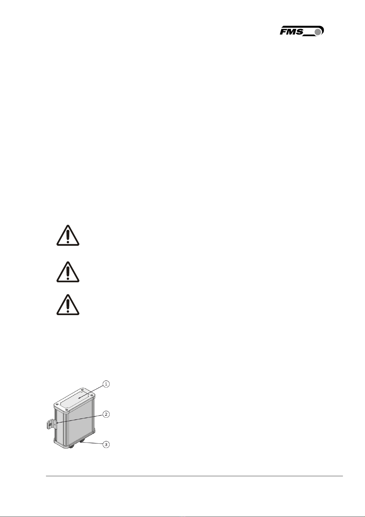
3.3 Main Components ........................................................................................................................................ 5
3.4 Scope of Supply ........................................................................................................................................... 6
4 INSTALLATION .................................................................................................................................................... 7
4.1 As-delivered Condition ................................................................................................................................. 7
4.2 Preparation ................................................................................................................................................... 7
4.3 Installation of the FMS-cradleGUARD.T Transmission Module ................................................................... 7
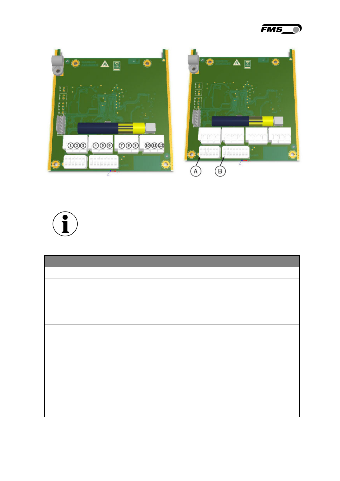
4.4 Electrical Connection of the FMS-cradleGUARD.T Transmission Module .................................................. 8
4.4.1 Connection of Sensors and Switches .................................................................................................... 10
4.5 Electrical Connection of the FMS-cradleGUARD.R Receiver Module ....................................................... 12
5 DISPLAY AND OPERATION ............................................................................................................................. 13
5.1 Configuration on the Device ....................................................................................................................... 14
5.2 Display ........................................................................................................................................................ 16
5.3 Configuration via Web Interface ................................................................................................................. 16
6 TECHNICAL DATA ............................................................................................................................................ 23
6.1 FMS-cradleGUARD.R Receiver Module .................................................................................................... 23
6.2 FMS-cradleGUARD.T Transmission Module ............................................................................................. 23
6.2.1 Lifetime of Batteries ............................................................................................................................... 24
6.3 Certifications ............................................................................................................................................... 24
7 DIMENSIONS ..................................................................................................................................................... 25
7.1 FMS-cradleGUARD.R Receiver Module .................................................................................................... 25
7.2 FMS-cradleGUARD.T Transmission Module ............................................................................................. 26
8 TROUBLESHOOTING, FAQ .............................................................................................................................. 27

FMS-cradleGUARD Operating Manual and Installation Instructions
24.07.2019
3
2 Safety Information
All safety information, operating and installation regulations listed here ensure proper
function of the device. Safe operation of the systems requires compliance at all times.
Noncompliance with the safety information or using the device outside of the specified
performance data can endanger the safety and health of persons.
Work with respect to operation, maintenance, retrofit, repair, or setting of the device
described here must only be performed by expert personnel.
2.1 Presentation of Safety Information
2.1.1 Danger that Could Result in Minor or Moderate Injuries
Danger, warning, caution
Type of danger and its source
Possible consequences of nonobservance
Measure for danger prevention
2.1.2 Note Regarding Proper Function
Note
Note regarding proper operation
Simplification of operation
Ensuring function
2.2 General Safety Information
Flying parts
If the battery cover is not secured correctly, it can be ejected in the
case of rotating machines.
Tighten the screws of the cover sufficiently.
Changes or modification to this device that have not been expressly
approved by FMS AG, will result in the approval for operation of this
device being voided.

FMS-cradleGUARD Operating Manual and Installation Instructions
24.07.2019 4
The function of this system is only ensured with the components in
the specified layout to one another. Otherwise, severe malfunctions
may occur. Thus, the installation information on the following pages
must be followed.
The local installation regulations ensure the safety of electrical
systems. They are not considered in these operating instructions.
However, they must be met.
Electrical connections must be implemented by an expert.
All system components are sensitive components that can be
damaged in the case of improper installation! Installation must be
performed by trained service personnel!

FMS-cradleGUARD Operating Manual and Installation Instructions
24.07.2019 5
3 Product Information
3.1 Functional Description
The FMS-cradleGUARD consists of two different system components. A transmission module
(FMS-cradleGUARD.T) per cradle contains terminal blocks for up to 3 sensors and the radio
module. The radio frequencies can be clearly separated and ensure operational safety. The
receiver module (FMS-cradleGUARD.R) outside of the machine receives the signals of the
individual transmission modules and indicates their status in plain text on the display. The
integrated relay outputs can be connected directly to the PLC and a warning indicator. The
system can be conveniently configured via the web interface using a browser.
3.2 System Requirements
The FMS-cradleGUARD is an independent system. Respective sensors must be present on the
machine.
3.3 Main Components
Figure 1: FMS-cradleGUARD Main Components
FMS_cradleGUARD_BA_Manual.ai

FMS-cradleGUARD Operating Manual and Installation Instructions
24.07.2019 6
Main component designations
Item Description
Item 1 FMS
-
cradleGUARD system components
1a Receiver module FMS
-
cradleGUARD.R, status display for up to 42
transmission modules
1b Transmission module FMS
-
cradleGUARD.T with inputs for sensors,
incl. batteries
1c Alternative status indicator and configuration via web interface
Item 2 Connection to main control
2a Connection to PLC, relay outputs
Item 3 Sensors on spool cradle
3a Up to 3 per FMS
-
cradleGUARD.T transmission module or per cradle
not shown 24 VDC connection for FMS
-
cradleGUARD.R receiver module, Ethernet
cable, etc.
Table 1: Main Components
3.4 Scope of Supply
Scope of supply:
Receiver module FMS-cradleGUARD.R, transmission module(s) FMS-cradleGUARD.T with
batteries and fastening brackets, installation instructions, and operating manual
The following is not included in the scope of supply:
Sensors (including cables), installation material; installation and start-up: our experts will
assist you upon request
Accessories:
24 VDC power supply for FMS-cradleGUARD.R receiver module, patch cable for the
connection of receiver module and (e.g.) laptop for configuration via web interface.

FMS-cradleGUARD Operating Manual and Installation Instructions
24.07.2019 7
4 Installation
4.1 As-delivered Condition
FMS-cradleGUARD.R Receiver Module
- IP address 192.168.000.090
- Radio channel preset
FMS-cradleGUARD.T Transmission Module(s)
- Radio channel preset
- To keep them apart, the individual transmission modules are labeled with individual ID.
The ID can be found on a label on the housing.
- The batteries are enclosed and must be inserted.
4.2 Preparation
When installing the system components, the following conditions must be met to ensure
proper function.
The components may not be subjected to loads outside of the
specified values during installation and operation later.
The fastening points for supporting the components must be
designed correctly. Pay attention to proper installation of the FMS-
cradleGUARD.T transmission modules on the machine.
The sensors must be connected electrically correctly.
4.3 Installation of the FMS-cradleGUARD.T Transmission Module
The receiver modules must be installed on the cradle on a flat surface. The contact surfaces
must be as even as possible.
Use the enclosed fastening brackets for installation.
Figure 2: FMS-cradleGUARD.T
FMS_cradleGUARD_BA_Manual.ai

FMS-cradleGUARD Operating Manual and Installation Instructions
24.07.2019
8
FMS
-
cradleGUARD.R
Item Description
1 Cover in front of battery compartment
2 Mounting bracket (2 pcs)
3 Cover with PG gland for electrical connections
Table 2: FMS-cradleGUARD.R
Battery access
Ensure easy access to the battery when selecting the installation
location.
Installation direction
During alignment of the housing, make sure that the side with the
electrical connections points downward if possible.
In the case of small machines and light
-
weight cradles, make sure
that the additional weight of the transmission module may have to
be compensated to avoid any imbalance.
We recommend a centered installation of the receiver modules on
the cradle to avoid this effect.
4.4 Electrical Connection of the FMS-cradleGUARD.T Transmission Module
We recommend a cable with 3 x 0.5 mm
2
for the sensor connection. The cables must be
routed separately from power cables.
If you choose to use the 24 VDC power supply, please make sure to use a cable 3 x 0.5 mm
2
.
First, remove the cover on the connection side. Next, the board with the terminal blocks can
be pulled as far as it goes.

FMS-cradleGUARD Operating Manual and Installation Instructions
24.07.2019
9
Figure 3: FMS-cradleGUARD.T Terminal Designation and Connection
FMS_cradleGUARD_BA_Manual.ai
Designation of sensors
You can modify the below stated names (Pintle,…) of the sensors via
the web browser.
FMS
-
cradleGUARD.R
Item Description
1 to 3 Sensor 1 – PINTLE LEFT (pintle lock left)
Terminal 1: +12 VDC power supply (can be measured using an
oscilloscope only)
Terminal 2: Signal / switch
Terminal 3: GND / reference
4 to 6 Sensor 2 – PINTLE RIGHT (pintle lock right)
Terminal 4: +12 VDC power supply (can be measured using an
oscilloscope only)
Terminal 5: Signal / switch
Terminal 6: GND / reference
7 to 9 Sensor 3 – WIRE BREAK
Terminal 7: +12 VDC power supply (can be measured using an
oscilloscope only)
Terminal 8: Signal / switch
Terminal 9: GND / reference

FMS-cradleGUARD Operating Manual and Installation Instructions
24.07.2019 10
FMS
-
cradleGUARD.R
Item Description
10 to 12 24 VDC (18 to 36 VDC) power supply, sustitutes batteries
Terminal 10: +12 VDC
Terminal 11: GND
Terminal 12: PE
not shown Battery compartment
A Dip switch for channel assignment (do not change!)
B Dip switch for setting the ID (do not change!)
Table 3: Terminal Block for FMS-cradleGUARD.T Sensors
Do not change the Dip switches!
Changing the Dip switches will result in the loss of the radio
connection.
4.4.1 Connection of Sensors and Switches
Proximity switch
When proximity switches are used, the time delay before availability)
must be ≤50 ms.
The power supply to the switch is 12 VDC. Switches with a typical
power supply (e.g. 10 to 30 VDC) can be used.

FMS-cradleGUARD Operating Manual and Installation Instructions
24.07.2019 11
Figure 4: Sensors and Switches FMS_cradleGUARD_BA_Manual.ai

FMS-cradleGUARD Operating Manual and Installation Instructions
24.07.2019 12
4.5 Electrical Connection of the FMS-cradleGUARD.R Receiver Module
First, remove the cover from the front side of the component for the connection. The cover is
secured with 4 countersunk-head screws.
We recommend a 3 x 0.5 mm2cable for the power supply. The cable must be routed
separately from the power cable.
Figure 5: Electrical Connection of the FMS-cradleGUARD.R FMS_cradleGUARD_BA_Manual.ai
Electrical connection of the FMS
-
cradleGUARD.R
Item Description
1 24 VDC (18 to 36 VDC)
2 GND
3 PE
16, 26 Relay 1/1 – 1/2
17, 27 Relay 2/1 – 2/2
18, 28 Relay 3/1 – 3/2
19, 29 Relay 4/1 – 4/2
A RJ45 socket for Ethernet
Table 4: Electrical Connection of the FMS-cradleGUARD.R

FMS-cradleGUARD Operating Manual and Installation Instructions
24.07.2019 13
5 Display and Operation
Figure 6: Control Panel and Display FMS_cradleGUARD_BA_Manual.ai
FMS
-
cradleGUARD.R
Item Description
1 Antenna
2 Upper fastening lug
3 Display

FMS-cradleGUARD Operating Manual and Installation Instructions
24.07.2019 14
FMS
-
cradleGUARD.R
Item Description
4 Navigation keys
Left – Scroll parameter list to the left
Right – Scroll parameter list to the right
Up – Increase parameter value
Down – Decrease parameter value
5 Enter key
Select parameter, confirmation
6; 7 Menu key, status LED
By pressing and holding the menu key (> 3 seconds), you can enter the
configuration menu of the system parameters. The status LED lights up
until you exit the menu by pressing and holding the menu key again (> 3
seconds).
8 Cover with 4 fastening screws
9 PG gland for cable feed
-
through (24 VDC)
10 Lower fastening lug
Table 5: FMS-cradleGUARD.R
5.1 Configuration on the Device
Only a basic parameter can be set on the device. The configuration itself has to be done via
the web interface.
By pressing and holding the menu key (> 3 seconds), you can enter the menu of the system
parameters.
- By pressing on the “left” and “right” keys, you can navigate through the parameter list.
- By pressing the enter key, you select the system parameter to be changed.
- Now, the name of the parameter to be changes is flashing
- By pressing the “up” and “down” keys, the parameter value can be changed.
- By pressing the enter key, you confirm your input and the changed value is saved.
- Press and hold the menu key again (>3 seconds) to exit the menu. If nothing is entered on
the device, the menu is automatically exited after 60 seconds.

FMS-cradleGUARD Operating Manual and Installation Instructions
24.07.2019 15
System Parameters
Parameter Description
IP address The IP address must be entered in 4 blocks.
Min. 0
Max. 255
Default value 192.168.000.090
Subnet The address must be entered in 4 blocks.
Min. 0
Max. 255
Default value 255.255.255.0
Gateway The address of the gateway must be entered in 4 blocks.
Min. 0
Max. 255
Default value 255.255.255.0
Language Display language on the device display
Min. German
Max. English
Default value English
CustomNa Customized designation of sensors
Min. disabled
Max. enabled
Default value disabled
T cycle Cycle time for communication between transmitter and
receiving modules
Min. 840 ms (only recommended when
24 VDC is connected)
Max. 8400 ms
Default value 8400 ms
Table 6: System Parameters

FMS-cradleGUARD Operating Manual and Installation Instructions
24.07.2019
16
5.2 Display
If configured sensors or switches are activated this will be shown on the display.
Figure 7: Display during start-up and without error FMS_cradleGUARD_BA_Manual.ai
Figure 8: various error messages FMS_cradleGUARD_BA_Manual.ai
Line 1 – individual ID of the transmission module FMS-cradleGUARD.T
Line 2 – specific error message
If multiple errors occur at the same time, the display will switch and indicate all errors in
sequence.
5.3 Configuration via Web Interface
The system can be integrated in an Ethernet network and configured via a browser (e.g.,
Internet Explorer 8 or higher). The FMS-cradleGUARD.R receiver module has a static IP
address, which can be set via the control panel. The IP address is not automatically obtained
via DHCP.
Alternatively, the system can be configured using a desktop or laptop computer via a peer-to-
peer connection. However, the computer must be disconnected from the network and have a
static IP address for this purpose. The static IP address must not be identical with the IP
address of the receiver module.
Follow the instructions as soon as the connection is established:
- Open a browser (e.g., Microsoft Internet Explorer, Mozilla Firefox, etc.)
- The default address of the receiver module is 192.168.000.090. If you have not change it,
enter this IP address into the input field (e.g., http://192.168.000.090) and confirm with
“Enter.”
User interface language
The user interface of the browser is only available in English

FMS-cradleGUARD Operating Manual and Installation Instructions
24.07.2019 17
Figure 9: Home FMS_cradleGUARD_BA_Manual.ai
Web Interface – Home
Item Description
1 Page navigation
Table 7: Home
Figure 10: Current Reading FMS_cradleGUARD_BA_Manual.ai

FMS-cradleGUARD Operating Manual and Installation Instructions
24.07.2019 18
This a purely informative page only. You cannot edit anything.
Web Interface – Current Reading
Item Description
1 Information on the display
2 Status indicator for relay outputs
3 List of sensors 1 to 21
4 List of sensors 22 to 42 (not illustrated)
Depending on the zoom factor of the browser window, the tables can also
be arranged among each other.
5 Column “ID” (IDentification)
Every FMS-cradleGUARD.T transmission module has its own ID number for
easy assignment.
The ID can be found on a sticker on the housing.
6 Column with sensor names
Preset names Pintle left/right, wire break
Names can be modified individually.
7 Sensor status
Green - OK
Red - Fault
Table 11: Current Reading
The table always contains all available 42 transmission modules. Status messages are only
displayed for the active transmission modules.

FMS-cradleGUARD Operating Manual and Installation Instructions
24.07.2019
19
Figure 8: Sensor Settings FMS_cradleGUARD_BA_Manual.ai
Web Interface – Sensor Settings
Column Description
ID ACTIVE Using this checkbox, the transmission module with the
respective ID is activated.
As soon as it is activated, it appears in the “Current
Reading” window.
Terminal Block
1 to 3
Pintle left
The individual columns stand for the 3 sensors that can be
connected per transmission module.
3 different connection possibilities can be selected
Deactivated
No sensor is connected. The sensor status is not shown on
the display.
Active = 0 (NPN)
NPN: Sensor switches ground (GND)
Active = 1 (PNP)
PNP: Sensor switches the positive signal (+12 V)
Terminal Block
4 to 6
Pintle right
Terminal Block
7 to 9
Wire break / Tilt
switch
Table 9: Sensor Settings
Save changes
If you made changes, you must confirm them using “Save changes.”
Otherwise, your entries will be discarded once you leave the page!
You may have to scroll down on the page to see the save key.

FMS-cradleGUARD Operating Manual and Installation Instructions
24.07.2019 20
Figure 12: Relay Settings FMS_cradleGUARD_BA_Manual.ai
You can define individual trigger conditions for the 4 relay outputs in the receiver module.
Web Interface – Relay Settings
Function Description
Disabled Without function
Pintle left If 2 pintles exist on the cradle, they can be differentiated
here.
Pintle right
Wire Break Detection of a wire break using the respective sensor.
The response time until relay triggering can be up to 8.4
seconds.
Tilt Is mainly used for tubular type stranders and to detect
cradle swinging.
Radio lost The quality of the radio connection of the individual
transmission modules is checked continuously. A relay can
be switched in the case of a poor connection.
Battery low Is activated if the charging status of the battery drops below
20%. A runtime of a few days is left prior to battery
replacement. This alarm does not affect the Master alarm.
Master alarm Is activated as soon as any fault state occurs, regardless of
the configuration of other relay outputs.
Table 10: Relay Settings
Table of contents
Other FMS Industrial Equipment manuals
Popular Industrial Equipment manuals by other brands

BWT
BWT ET-NU25 Installation and operating instructions

Mennekes
Mennekes AMAXX Installation and operating manual

WEISS
WEISS ST Series Assembly and instruction manual

KTR-Group
KTR-Group KTR-STOP S-A-F B Series Operating & assembly instructions

TGW
TGW NBS 90 SP Installation, operation & maintenance manual

Showa Denki
Showa Denki CRN Series Operation manual

CMCO
CMCO TIGRIP THM 120 operating instructions

Thermal Edge
Thermal Edge A2W30120 User's & technical manual

schmalenberger
schmalenberger fluvo CG700 rondo operating instructions

Siemens
Siemens SIMATIC NET RUGGEDCOM RX1500 installation manual

ABB
ABB 80307300R Operation manual

ABB
ABB HT842921 Operation manual