Foley Belsaw 200 User manual

Foley-Belsaw
Model 200 Key Machine
Adjustment & Operation
Instructions
Order No. R001128

Notes
Order No. Description Figure No.
5726003 Base K-350
5726005 Slide Casting K-351
5726006 Clamp K-353
5726007 Spring K-354
5726008 Tracer Guide (Steel) K-355
5726009 Tracer Guide (Duplicating) K-356
5726013 Tracer Guide (Code) K-357
5726014 Guide Arm Casting K-358
5726015 Retainer Washer K-361
5726903 Stud K-362
5726017 Shaft K-363
5726018 Slide Shaft K-364
5726019 Pulley (Motor) K-365
5726001 Motor 110V K-366
5726029 Bearing K-367
5726028 Chip Guard K-368
5726021 Wing Nut K-369
5726022 Micrometer K-370
5726023 Pulley (Cutter Shaft) K-371
5726020 Bearing K-372
5726002 Belt K-374
Order No. Description Figure No.
5726025 Spring K-378
5726010 Slotting Cutter K-385
5726012 Duplicating Cutter K-386
5726011 Code Cutter K-387
5726026 Gauge K-388
5726027 Motor Mount K-389
5726653 Adjustment Key (each) K-390
Optional Equipment
5729727 Direct Read Digital
Micrometer Depth Kit
5729728 Direct Read Digital
Micrometer Spacing Kit
5729726 Both Direct Read
Micrometer Kits
5787427 Nylon Deburring Wheel K-391
5786696 Steel Wire Wheel (Coarse)
5786697 Steel Wire Wheel (Fine)
5749790 Work Station with Lamp,
Board, Box, & Feet
5749784 Flex Shaft Lamp
5749829 Board w/ Box & Feet
5727190 12V DC Motor
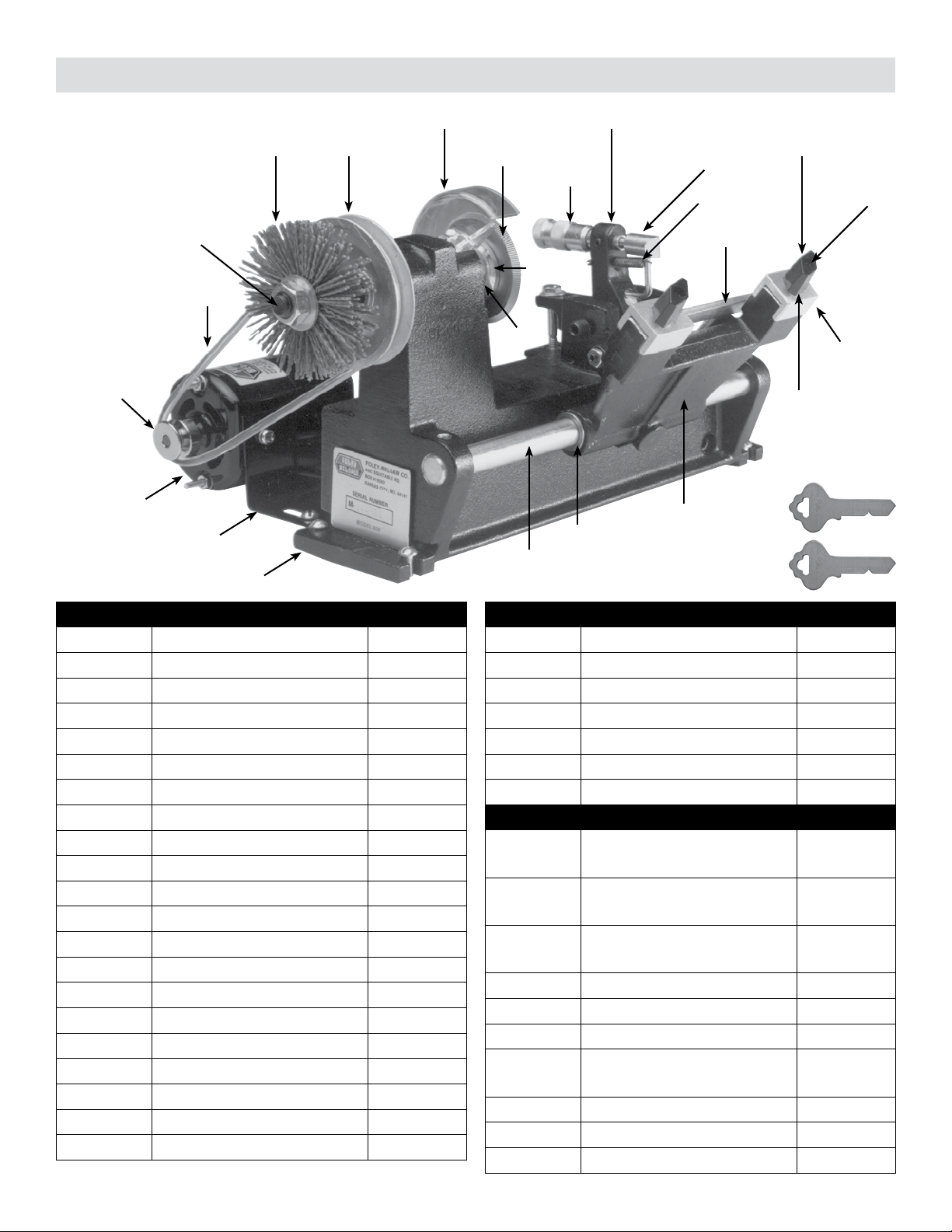
200 KEY MACHINE PARTS LIST
K-371
K-361
K-368
K-370
K-355
K-356
K-357
K-354
K-363
K-374
K-351
K-369
K-364
K-389
K-385
K-386
K-387
K-391
K-353
K-362
K-350
K-365
K-388
K-366
K-367
K-372
K-378
K-358
K-390
Upgrade turns your Model 200 Key Machine into a code cutter worth hundreds of dollars, allowing you to
control both the depth and the spacing on your Model 200 machine with the accuracy of a direct read digital
micrometer. These two direct read digital micrometers are only found on key machines that cost hundreds, if
not thousands, of dollars more.
If you already have the digital spacing micrometer, then you know how much easier these micrometers are
to use and read. The reading is direct so you always know the setting. You no longer have to remember how
many revolutions you made or go back to 0 every time. Just dial the number in and make your cut. The depth
micrometer comes with a new casting drilled to t the larger shaft on the micrometer and new tracer guides to
t the barrel of the micrometer.
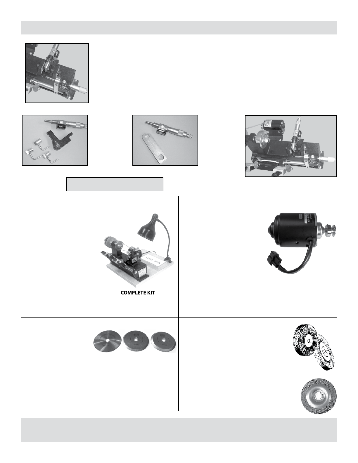
UPGRADE YOUR MODEL 200 KEY MACHINE
COMPLETE MODEL 200 KEY MACHINEDirect Read Digital Micrometer Depth Kit
Kit includes:
digital mic.,
one each
tracer guide,
guide arm
casting and
instructions.
Direct Read Digital Micrometer Spacing Kit
Kit includes:
digital mic.,
mounting
bracket, &
instructions.
Order No. 5729727 Order No. 5729728
SAVE WHEN YOU BUY BOTH TOGETHER!
Order No. 5729726 Model 200 Key with both micrometers
Order No. 5729729
Everything you need to make your Model 200 Key
Machine portable. This 3/4” hardwood board is just the
right size and light enough to carry to the job. Your
board comes with pre-drilled holes, mounting
screws and rubber feet. The work
station comes complete with a
heavy duty storage box— to store
your extra cutters, tools and
parts -- and a gooseneck lamp.
COMPLETE KIT
Order No. 5749790
FLEX SHAFT LAMP (ONLY)
Order No. 5749784
BOARD WITH RUBBER FEET AND BOX
Order No. 5749829
12 VOLT D.C. MOTOR FOR MODEL 200
Many students and customers
use their Model 200 Key Machines
in their cars, trucks or vans. This
12V motor allows you to use the
Model 200 in any mobile applica-
tion where 12V power is available.
Includes:
zA Pulley
zA template to mark new
holes in the old motor mount
bracket from the 110 volt mo-
tor (Reuse the same bracket
and mounting screws from
the 110V motor).
Order No. 5727190
FOLEY-BELSAW KEY MACHINE WORK STATION
KEY CUTTERS
Worn cutters grind slowly and
can cause slips that spoil blanks
and prevent accurate duplica-
tion. These cutters will t any
Foley-Belsaw Model 200 Key
Machine.
Steel Cutter
Order No. 5726010
Code Cutter
Order No. 5726011
Duplicating Cutter
Order No. 5726012
NYLON REPLACEMENT BRUSH
This carbide impregnated brush deburrs faster
and smoother than wire and lasts 6 times longer.
Non- aring design prevents ying wire strands.
Fits the Foley-Belsaw Model 200 Key Machine.
Order No. 5787427
STEEL WIRE BRUSHES
Made to t your Foley-Belsaw Machine, these
brushes are excellent for removing burrs and
tarnish and polishing brass key blanks. Made
in coarse or ne steel for all types of work.
We recommend the coarse for regular key
deburring. Brushes are 4”diameter with a 1/2”
hole.
Order No. 5786696…Coarse
Order No. 5786697…Fine
6010 6011 6012
200 KEY MACHINE OPTIONAL ACCESSORIES
Place your order M-F 8am to 4:30pm (CST) call toll free:
1-800-821-3452 fax: 816-483-5010 online: www.Foley-Belsaw.com
1
The key machine is the locksmith’s primary tool and one your best sources of income. The basic function of a
key machine is to duplicate keys accurately. It is a delicate piece of equipment and requires the maintenance
and care of any precision machine. It should be used for the purpose it is designed for and not for general
shop use. Once your key machine is set up and properly adjusted it will remain that way if you do not abuse it
through misuse. A good key machine, properly set up and adjusted, will accurately duplicate a key within one
or two thousandths of an inch. This accuracy is necessary to properly duplicate keys that will actually work.
A locksmith takes great pride in keeping his key machine set up for accurate duplication. Many key machines
in use today do not duplicate properly because they are not adjusted or operated properly. You have no doubt
heard the complaint of people who had keys duplicated in service stations, dime stores, and hardware stores,
only to nd out that they didn’t work when they tried to use the new key. The reason for this is not usually the
key machine, but the lack of experience on the part of the operator and improper set-up of the machine.
Your Foley-Belsaw Model 200 Key Machine has been designed with precision, accuracy, and versatility in
mind. Special features have been incorporated into the design to make it a combination key duplicating ma-
chine and a code cutting machine. These instructions will deal with the installation and operation of the ma-
chine for duplicating cylinder keys. Cutting keys by code and cutting at steel keys will also be covered.
The location of your key machine is very important. It should be set up in a place in your shop that offers natu-
ral light if at all possible. A bench tool light should also be used. You should have enough work area to allow
for a key display board to be hung on the wall beside or behind the machine for easy accessibility.
INTRODUCTION
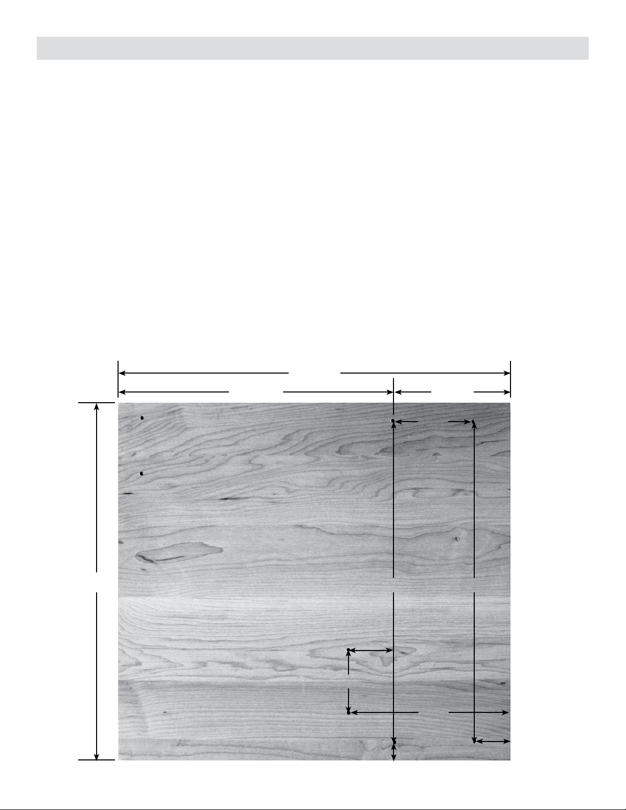
13-1/2”
12-1/2” 11”
2-3/4”
1-5/16”
3/4”
1-9/16”
2-3/16”
11”
9-7/16” 4-1/16”
5-5/8”
Figure A
2
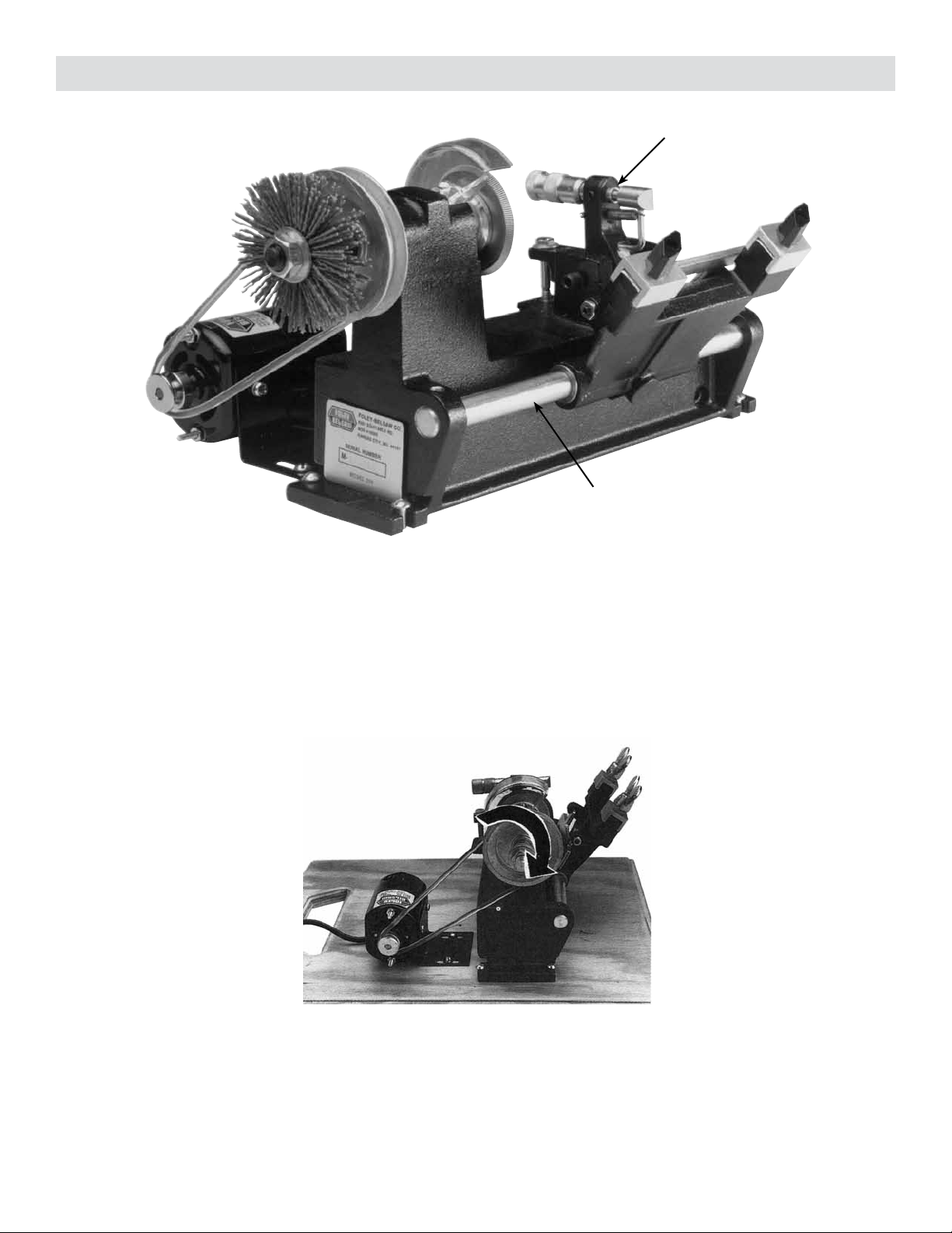
There are two ways of mounting your key machine: directly to your work bench or on a piece of wood, for use
as a portable machine. A portable machine is great to take to a job site or for use in a mobile shop with a power
inverter or the optional 12 volt motor. This setup makes your machine much more versatile.
If you mount the machine on a bench, it should be approximately 36” from the oor. This height will give
the average person a good view of the working parts of the machine without having to stoop over. The actual
dimensions for the board should be approximately 13” x 12-1/2” x 3/4” plywood or hardwood. Figure A shows
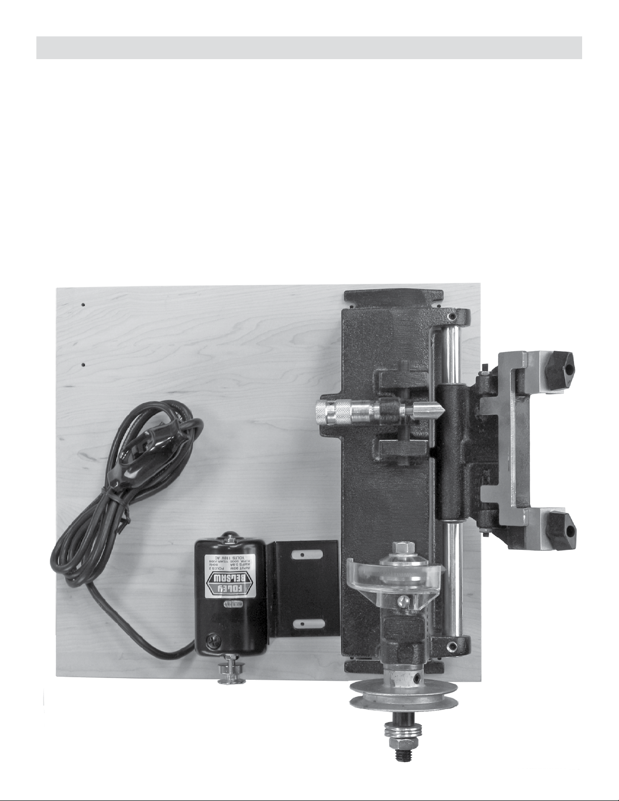
an example of a mounting board. Figure A-2 shows the machine mounted on the board and the six mounting
holes. You can also cut a hole in the handle to carry the machine and mount rubber feet on each bottom corner
for stability on uneven surfaces. Foley-Belsaw also sells a board with rubber feet and a tool box (5749829), a
lamp (5749784), or both together (5749790).
Figure A-2
MOUNTING BOARD

3
Figure # Description
B-1 Motor
B-2 Motor Pulley
B-3 Drive Belt
B-4 Machine Pulley
B-5 Key Cutter
B-6 Initial Depth Adjustment Setting Screws
B-7 Micrometer
B-8 Key Guide
B-9 Right Hand Key Vise Clamping Handle
Figure # Description
B-10 Right Hand Key Vise
B-11 Left Hand Key Vise Clamping Handle
B-12 Left Hand Key Vise
B-13 Carriage
B-14 Lateral Adjustment Screw
B-15 Carriage Guide Bar
B-16 Base Casting
B-17 Key Guide Spring
B-18 Shoulder Gauge
B-7 B-8
B-17
B-3
B-13
B-9
B-15
B-5
B-10
B-2
B-18
B-1
B-6
Figure B
B-4
B-12
B-11
B-14
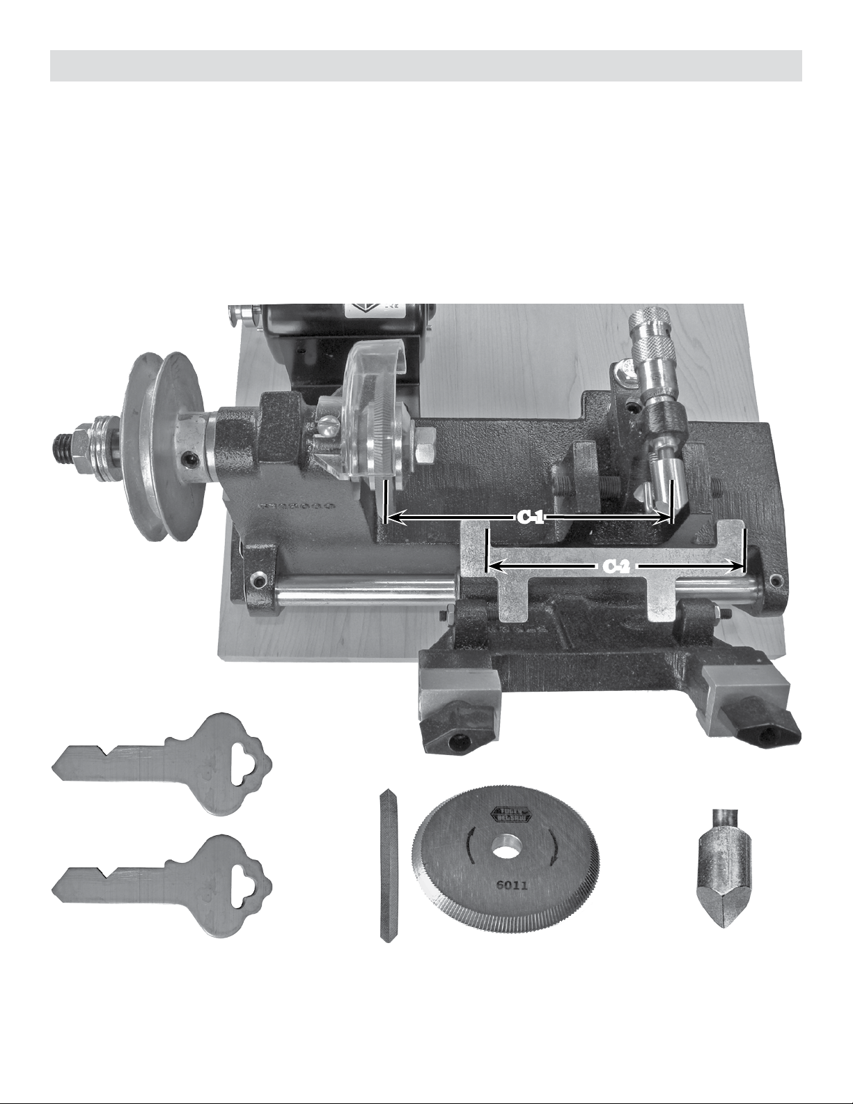
Figure B shows the major parts of your key machine. Study these carefully as we will be referring to them quite
frequently.
PARTS OF THE MACHINE
4
INITIAL ADJUSTMENTS
Your machine has been set at the factory, however, a slight adjustment may be necessary. You must have the
Code Key Cutter (5726011) and the Code Tracer Guide (5726013) installed to make these adjustments. These
have been installed at the factory and are recognizable by their V-shape designs. The rst adjustment you
should check on your machine is the lateral adjustment. The distance between the CODE KEY CUTTER and
the CODE KEY GUIDE must be the same as the distance between the faces of the B-18 SHOULDER GAUGE.
See Figure C. THE DISTANCE BETWEEN THE CUTTER AND GUIDE, AS SHOWN AT C-1, MUST BE
THE SAME AS THE DISTANCE BETWEEN THE FACES OF THE SHOULDER GAUGE AS SHOWN AT
C-2. There is a SPECIAL SET OF ADJUSTMENT KEYS in your parts bag that you will use to set up your
machine. Notice these two keys are identical and each has a large V-shaped groove.
C-2
C-1
SPECIAL SET OF ADJUSTMENT KEYS
Figure C
CODE CUTTER CODE GUIDE
5
INITIAL ADJUSTMENTS
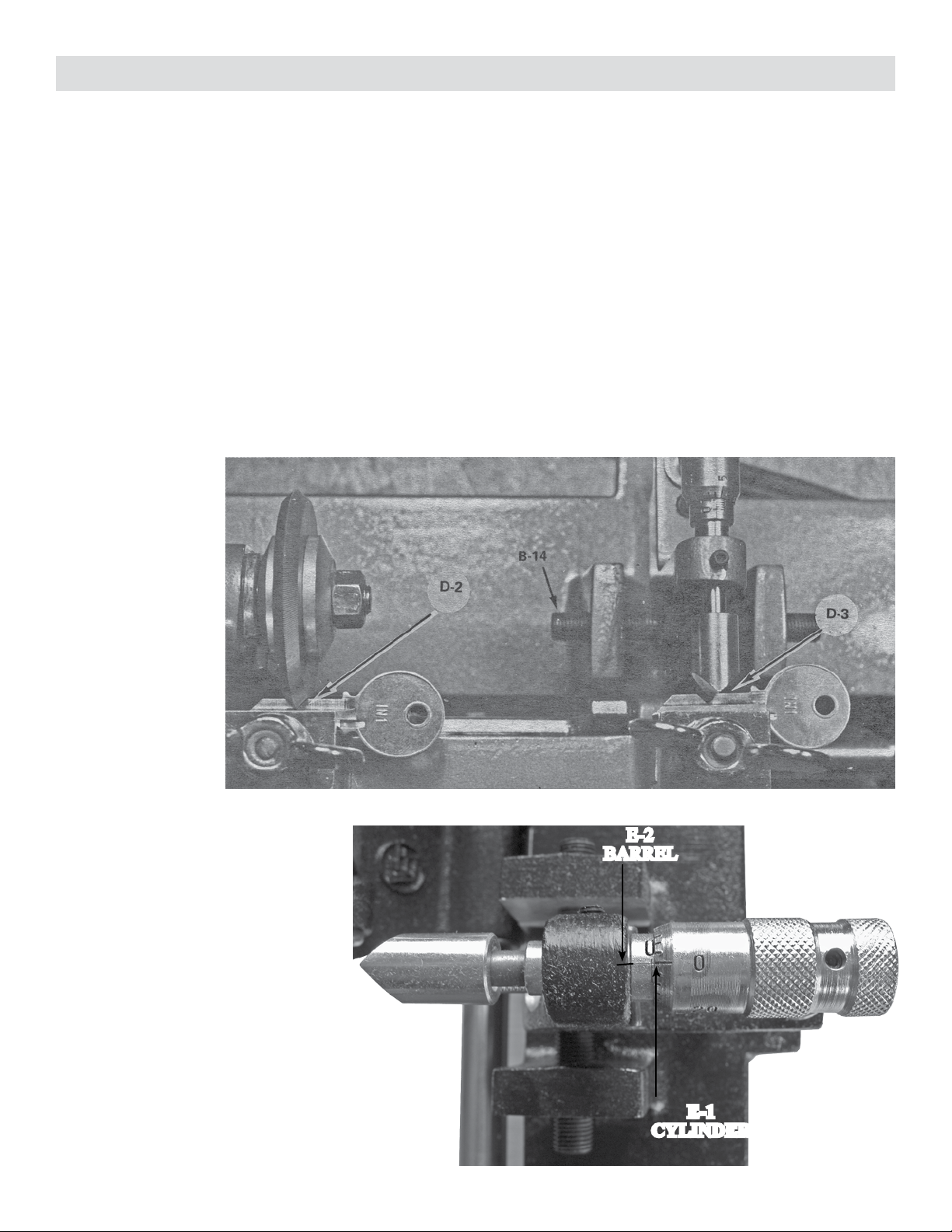
1. MAKE THE LATERAL (SIDE-TO-SIDE) ADJUSTMENT
First, raise the B-18 shoulder gauge up against the key vises. Now insert both adjustment keys in the vises
and line up the front shoulder of both keys as they touch the faces of the shouldering gauge.... tighten both
keys in the vises and lower the shouldering gauge. Raise the carriage so the “V” in the adjustment key in the
LEFT hand vise contacts the key cutter as shown at D-2, Figure D. Notice where the guide contacts the adjust-
ment key in the RIGHT hand vise. It may be off to one side or another as shown at D-3. As this gure shows,
it would be necessary to move the key vise to the RIGHT to make it line up, or move the guide to the LEFT.
Since the key vise cannot be moved, it will be necessary to move the guide to the left until the point is in the
bottom of the “V” of the adjustment key.
To move the guide to the left, rst loosen the lateral adjustment screw shown at point B-14. On the right side is
another adjustment screw. Tighten the screw on the right to move the guide to the LEFT. If you need to move
the guide to the RIGHT, you will need to loosen the right screw and tighten the left screw. Make small adjust-
ments, always loosening one side and tightening the other. DO NOT OVERTIGHTEN. Continue doing this
until you have the point of the guide directly in line with the bottom of the “V” of the adjustment key. Don’t
worry if the guide
doesn’t touch the
bottom of the “V”,
as you will make this
adjustment in the next
step. Once, the guide
is centered in the
adjustment key blank
groove, tighten both
left and right screws
evenly.
Figure D
2. ZERO THE MICROMETER
The next step is to adjust the guide
until it touches the edge of the adjust-
ment key, while at the same time, the
cutter touches the edge of the adjust-
ment key in the left hand vise. First,
set the micrometer to 0 degree. See
Figure E. There are two basic parts
to your micrometer: the CYLINDER,
as shown at E-1, and the BARREL,
as shown at E-2. There is a 0 degree
setting on the cylinder at E-1 and a
0 degree setting on the barrel at E-2.
Turn the barrel until you line up the
two 0 degree settings as shown.
E-1
CYLINDER
E-2
BARREL
Figure E

6
3. MAKE THE LONGITUDINAL (FRONT-TO-BACK) ADJUSTMENT
Now, with the cutter rmly against the edge of the adjustment key, check to see where the key guide is in rela-
tionship to the adjustment key in the right hand vise (see note below). Does the guide have to go in or out? The
adjustment screws shown at B-6 will allow you to move the guide either forward or backward, as necessary.
There is one Allen screw and one hex head screw shown at B-6. The one at the back is the actual adjustment
screw. The one in the front, nearest to the guide, is the lock screw.
INITIAL ADJUSTMENTS
Figure E-1
To move the guide forward, turn the rear screw counter-clockwise and then turn the front screw clockwise to
lock the tilting segment in place. To move the guide back, you would rst have to loosen the front locking
screw, then turn the back adjusting screw clockwise. Then lock the front lock screw.
As you make the adjustment, hold the guide against the edge of the key and turn the cutter BY HAND. When it
just scrapes the key in the left hand vise, your machine will be in proper adjustment.
Note: It is recommended that you use two identical uncut key blanks for setting the key machine for proper
depth. The reason is so you will not ruin your special “V” keys used for lateral adjustment. Your depth adjust-
ments should be made at the center of the key blank, NOT at the tip or shoulder of the blade.
7
LUBRICATION AND CUTTER ROTATION
LIGHT OIL ON
MICROMETER SHAFT
Figure E-2
LIGHT OIL
ON SHAFT
• Use a light machine oil for the B-15 carriage guide bar
• Use medium grease on the key machine cutter shaft if tted with a grease zerk. Note: new current produc-
tion does not have a grease tting, because there is no lubrication needed on the main cutter shaft.
• Oil the carriage bar as needed to insure ease of operation. Be sure to keep this guide bar and the rest of the
machine clear of metal chips and shavings at all times.
• The motor does not require any lubrication.
The cutter rotation is very important. The le type cutter was installed on your machine at the factory with the
teeth pointing DOWN. All cutters have teeth pointing in the same direction. ALWAYS install the cutters as
shown in Figure F with teeth pointing DOWN. Installation of a cutter with the teeth pointing UP would make
the cutter work in the wrong direction and damage it. Also, the motor rotates in a direction so that the cutter
throws the chips and shavings down and away from your face, making it safer to operate.
Figure F

8
There are three types of cutters used on your machine. The “V” type le cutter was installed at the factory.
This cutter is for cylinder keys only. This “V” type le cutter can be used for both duplicating and cutting keys
by code. The other le cutter in the parts bag is the one you will be using most of the time. It is primarily for
duplicating cylinder keys. Steel keys should not be cut with these cutters. Only use the at steel cutter for cut-
ting steel keys.
CUTTERS AND GUIDES
CODE CUTTER
DUPLICATING CUTTER
STEEL CUTTER
CODE
GUIDE
DUPLICATING
GUIDE
STEEL
GUIDE
Since most of your cutting on the key machine will be duplicating keys, we’ll change over to the duplicating
cutter. You will be using the “V” type cutter more for code work, however, it can also be used for duplicating
cylinder keys.
In your parts bag, you will nd a le type duplicating cutter and matching guide. Notice that these guides are
made with the same angle as the cutter.

9
CHANGING CUTTERS AND GUIDES
First, remove the nut and the outside collar on the cutter shaft. Turn the nut counter-clockwise to remove.
Then, install the duplicating cutter as shown at G-1. Be sure the at side of the cutter is to your right as you
face the machine.
G-2
Figure G
G-2
Next, change the guide (see Figure G-1). Pull out the pin, shown at G-3, to release the spring. Pull the guide
G-2 straight forward and remove the spring. In the parts bag, there is another guide for duplicating. Slip the
spring on this guide and install it the same as the other guide. Put the pin back in to hold the spring in place.
Figure G-1
10
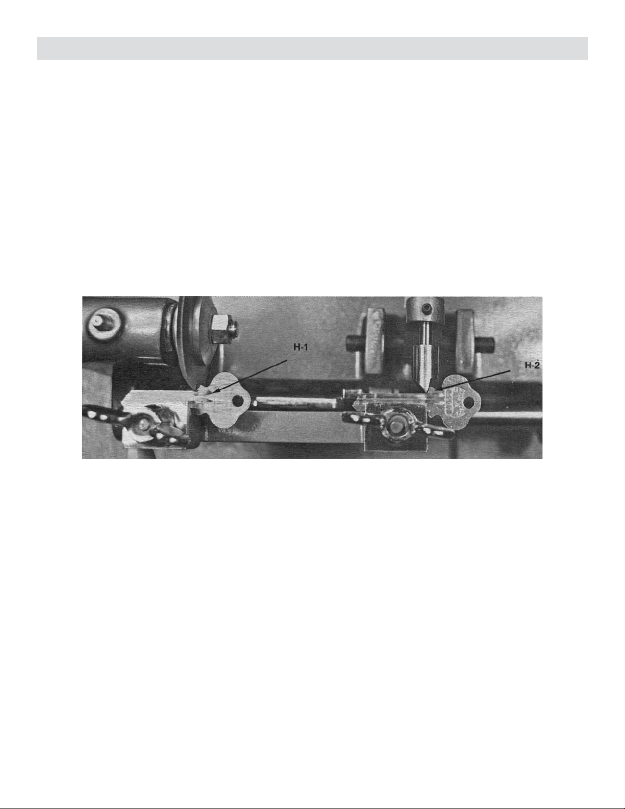
Your starting point for duplicating keys should always be at the shoulder. You should work toward the tip of the
key. Line up the shoulder of the key with the edge of the guide as shown at H-2. Then, line up the shoulder of
the blank with the edge of the cutter as shown at H-1.
Now, push the carriage toward the cutter and, with a forward pressure, SLOWLY move the carriage to the right.
Watch the key and the guide to see that the guide follows the cuts in the key. DO NOT WATCH THE KEY
THAT IS BEING CUT. On some keys, it may be necessary to make more than one pass across if there is a
series of very deep cuts. After the key is cut from the bow to the tip, recut it again from the tip to the bow. Now
take out the key you have just cut and scrape off all the burrs. The optional nylon (5787427) and wire brushes
(5786696 and 5786697) work perfect for deburring. Match your cut key with the original, the same as you did
in an earlier lesson on matching keys.
Placing the key and blank in the vise clamps properly, as well as using an even amount of pressure when cutting
is very important. As long as the starting point of your cutter (H-1) is the same as the starting point of the guide
(H-2), your key should be cut correctly.
DUPLICATING CYLINDER KEYS
If the key doesn’t work, check to make sure the cuts are not too deep or too shallow. If this is the case, you need
to make an adjustment with the adjustment screws at B-6 on page 7. Remember, these cutters may have high
spots on them and you will have to adjust the depth to the highest spot for accurate results. Determine the high
spots by turning the cutter a full revolution by hand until it just scrapes the adjustment key.
If your depth adjustment is correct and you have checked the spacing and found it okay, then you could be using
an uneven amount of pressure when forcing the key into the cutter. Try a lighter touch with your next key. You
will learn to use an even and proper amount of pressure with practice on the machine.
After reading the complete instruction manual, you should test your key machine for proper adjustment. The
best way to do this is to make a key. We suggest that you duplicate a key for your car or house, or maybe for a
padlock you have available. This way, you can check your nished product in the lock, making sure it works
properly.
Figure H
11
DUPLICATING FLAT KEYS
Now, we will cover the duplication of at keys and how to change over from making cylinder keys to making
at keys.
When changing from one cutter to another, it is always necessary to recheck the depth adjustment since every
cutter varies slightly in diameter. There are very few cutters that will be the same diameter down to two or three
thousandths of an inch. We can compensate for this difference in diameter by using the micrometer instead of
going to the trouble of resetting the depth adjustment. If the new slotting cutter for steel keys is larger than your
current cutter, turn the micrometer to move the guide farther out towards you. If the cutter is smaller, turn the
micrometer to move the guide in away from you.
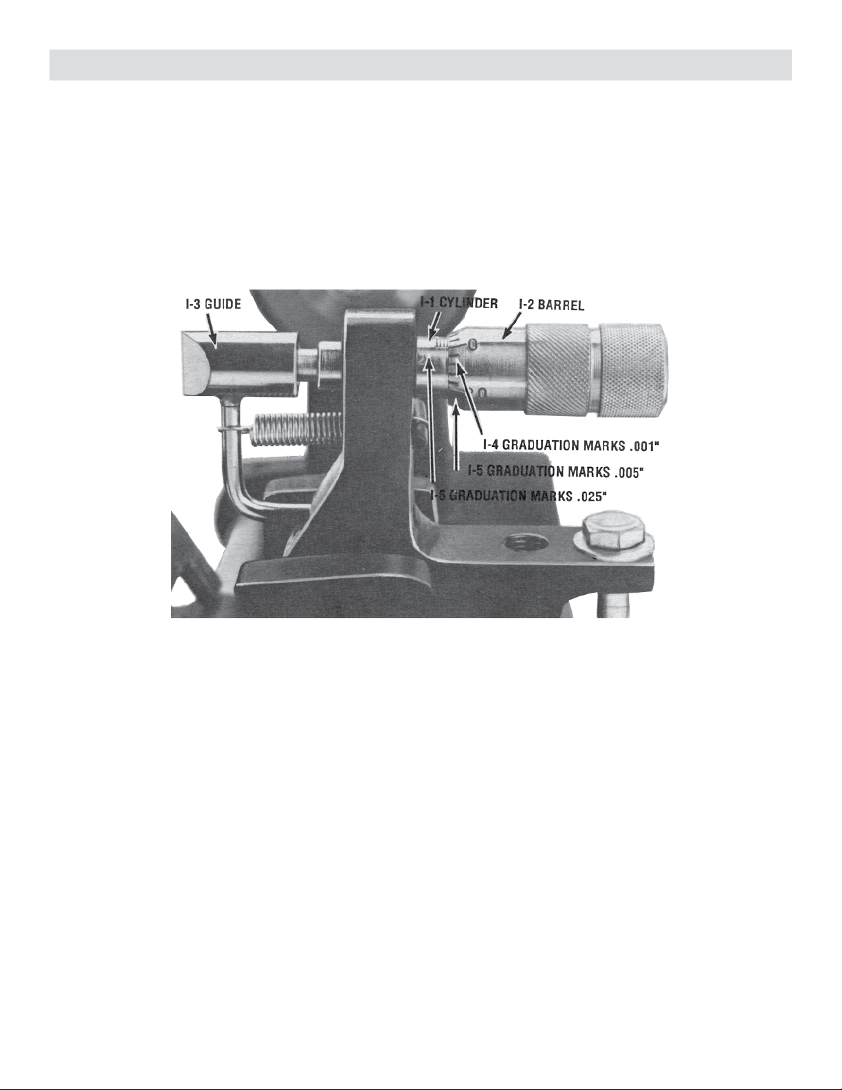
First, let’s study the construction of the micrometer again and look at how it works. Figure I shows how to read
a micrometer. I-1 is the CYLINDER, I-2 is the BARREL, and I-3 is the GUIDE. The small graduation marks
shown at I-4 on the barrel represent one thousandths of an inch (read .001”). Each time the barrel is turned from
one of these marks to the next, it moves the I-3 guide back or forward one thousandth of an inch (.001”).
Figure I
12
Figure I
DUPLICATING FLAT KEYS
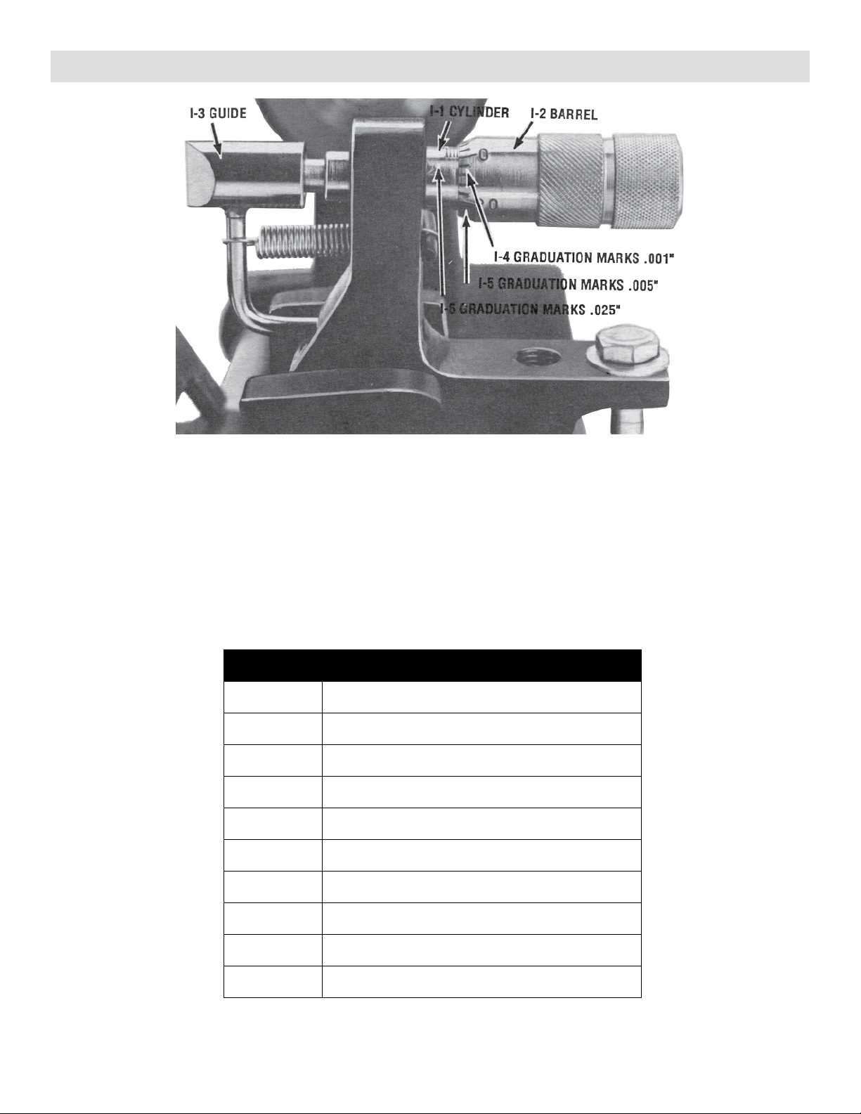
There are 25 of these graduation marks around the barrel which would equal twenty-ve thousandths of an inch
(.025”). If you turn the barrel one complete circle, you would move the I-3 guide .025”. The second graduation
marks on the barrel are shown at I-5. These are longer marks and represent ve thousandths of an inch (.005”).
By turning the barrel from one mark to another, such as from 0 degree to ve degrees, would move the guide
.005”. All you have to remember for the barrel graduation marks is that the short ones represent .001”, the long
ones represent .005”, and one complete circle represents .025”. Use the following chart below that shows the
decimal equivalents of the inch and how to read them on your micrometer:
Micrometer Equivalent in inches
.001” One thousandths of an inch
.005” Five thousandths
.025” Twenty-ve thousandths
.050” Fifty thousandths
.075” Seventy-ve thousandths
.100” One hundred thousandths
.125” One hundred and twenty-ve thousandths
.150” One hundred and fty thousandths
.175” One hundred and seventy-ve thousandths
.200” Two hundred thousandths

13
Figure I
DUPLICATING FLAT KEYS
Each graduation mark on the cylinder as shown at I-6 represents twenty-ve thousandths of an inch (.025”).
Now, with your micrometer setting on 0, turn it with your right hand to your RIGHT, one full turn. This repre-
sents .025” on the barrel markings. Notice that the barrel lines up with the second mark on the cylinder. Turn
it two more full turns and it now reads .075”. If you turn the barrel ve more points to the right, the reading
would be .080”. Now, turn the micrometer back to 0 and we will reset the machine to cut at steel keys.
It will be necessary to use a special guide to cut the steel keys since they have narrow slots and the guide used
for cylinder keys cannot be used. The guide must always have the same shape as the cutter. First, we’ll remove
the le cutter by rst removing the nut and outside collar. Install the slotting cutter for the steel keys on the
arbor. This cutter is packed in the parts bag. Be sure the teeth are pointing down toward you. Install the collar
and tighten the nut.
14
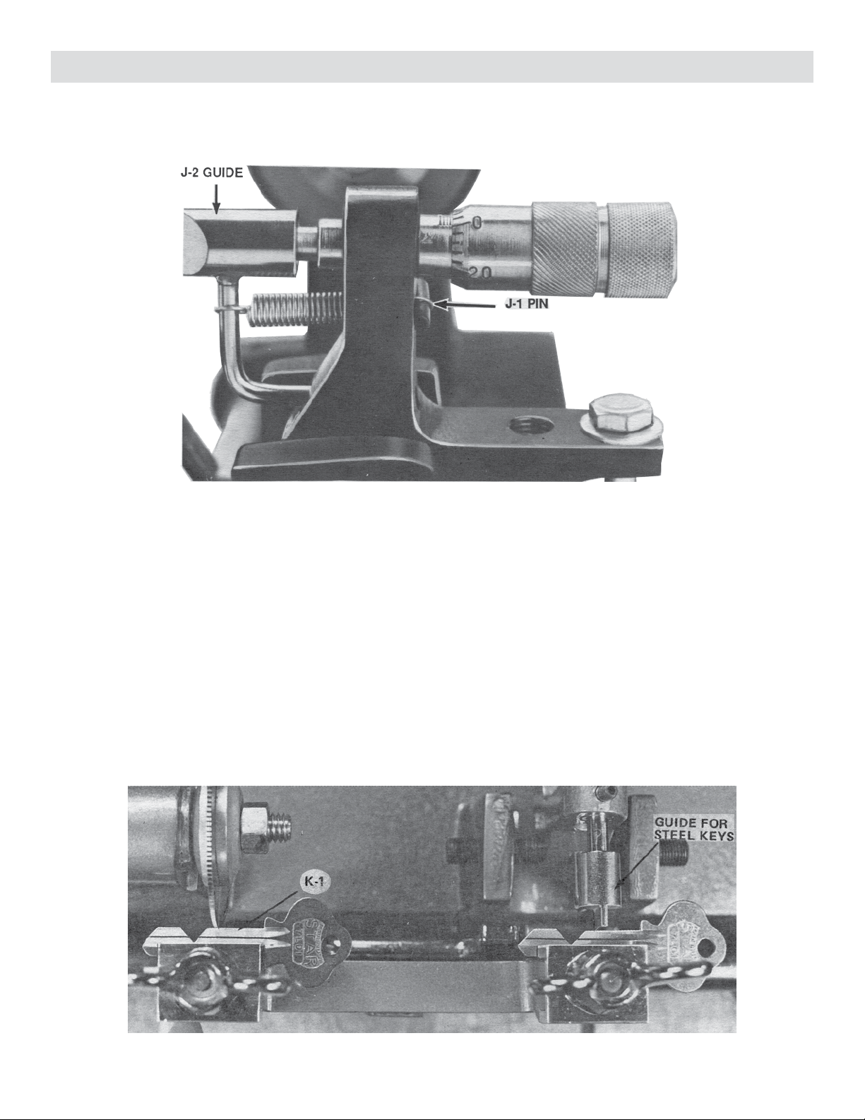
Next, change the guide. See Figure J. Pull out the pin, shown at J-1, to release the spring. Pull the guide J-2
straight out and remove the spring. In the parts bag there is another guide for the at steel keys. Slip the spring
on this guide and install it the same as the other guide. Put the pin back in to hold the spring.
DUPLICATING FLAT STEEL KEYS
Figure J
Clamp the two adjustment keys in the vises and raise the carriage to touch the cutter. See Figure K. Point K-1
shows the cutter touching the adjustment key. If the cutter does NOT touch the key, turn the micrometer to
the RIGHT SLOWLY until the key just touches the cutter. If the cutter touches the key and the right hand key
does NOT touch the guide, turn the micrometer to the LEFT SLOWLY until both touch as shown in Figure K.
Now, rotate the cutter slowly by hand. If it scrapes the key hard, turn the micrometer forward slowly until it
just scrapes the key. Next, read the micrometer setting. It may be almost the same as the other cutter or it may
be several thousandths low or high. Remember, each small mark on the barrel represents one thousandths of an
inch.
Record this reading. It may be ve or ten thousandths, either low or high. In the future, anytime you change
from the le cutter to the slotting cutter, all you have to do is to change the micrometer setting to the reading
you recorded and you are ready to duplicate at steel keys.
Figure K
15
DUPLICATING FLAT STEEL KEYS
The spacing will not be the same when using the slotting cutter since it is narrower, but we will not have to
change the lateral adjustment. STEEL KEYS CAN BE GAUGED OR MEASURED FROM THE TIP IN-
STEAD OF FROM THE SHOULDER.
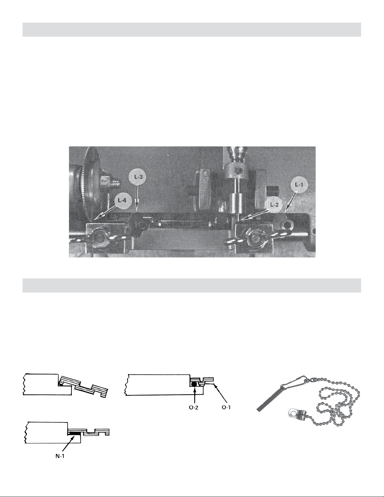
Figure L shows how to set up for cutting steel keys. First, clamp the key L-1 in the right hand vise and then line
up the tip of the key with the guide as shown at L-2. The blank L-3 goes in the left hand vise. Line up the tip
with the edge of the cutter, as shown at L-4. Tighten the clamp. Check to be sure that the key is touching the
guide at L-2 and that the blank is touching the cutter at L-4. Now, duplicate the cuts in the key. Make the cuts
straight in. DO NOT put side pressure on this cutter. If the slot must be wider that the cutter, make two cuts.
Make the rst cut straight in, all the way to the bottom. After you have all the cuts made, turn the key over and
make any additional cuts on the other side.
Figure L
Occasionally, you will run into a key that has grooves made in such a manner that it will be difcult to clamp
in the vise. When this occurs, it will be necessary to improvise a small shim in order to squarely clamp the
key. Figure M shows a blank with very little on the bottom side. If this blank were clamped in a vise, it would
have a tendency to tilt down as shown in Figure M. By the addition of a small shim, as shown in Figure N at
Point N-1, this blank could be clamped in the vise straight and square. These shims are usually made of scrap
metal or wire. Figure O shows another type of blank that may cause trouble in clamping. The rib shown at O-1
causes it to tilt either up or down. O-2 shows a small piece of wire inserted between the key and the vise to hold
the blank squarely. Foley-Belsaw sells a Brass Key Shim (5749644) that works well for many applications.
Figure M
Figure N
Figure O
SPECIAL HOLDING DEVICES
Brass Key Shim (5749644)

16
CODE CUTTING KEYS
To cut a key by code, it is necessary to change to your “V” type cutter and guide. Set the micrometer on 0-0
degree, and re-check your lateral and depth adjustments before cutting a key.
You rst have to determine the correct code or cuts on the key to cut a key by code. This information is pub-
lished in code books and available on special locksmith software. These are available from most locksmith
suppliers, including Foley-Belsaw.
It is also necessary to have a pre-cut spacer key for the lock you are working on. There is a special code spac-
ing attachment (5729728) for your Model 200 Key Machine that will eliminate the need for a pre-cut spacer
key or you can make your own spacer key from the empty lock plug. This is done by putting a key blank in the
empty plug and marking on the key through the empty pin chambers. You can use a sharp pointed tool like a
Locksmith’s Awl (5747543) or a Cylinder Plug Pin Marker (5747275). After making these marks, cut the key at
each mark, making each cut the same depth, approximately .025”.
Code books furnish you with the information on the depth and spacing of each cut. The depth given in code
books is measured from the root of the key to the bottom of the cut. In order to use these codes with your
Foley-Belsaw Key Machine, it will be necessary to subtract this distance from the width of an uncut blank. This
gives you the setting for your micrometer.
Example: If you wish to cut a key by code for an automobile, you would refer to your code book to nd the
correct cuts, looking at the depth chart for the depth of each cut. If the blank you are using is .250” wide and
you want to make a cut with a depth of .175”, you would subtract .175” from .250”, giving you .075”. You
would then back off your micrometer to .075” and make the cut.
After making this cut, you can check it by measuring from the bottom of the cut to the back of the key. It
should be .175”.
In your course, you will have practice lessons and supplies to cut keys by code with this machine.
Other manuals for 200
1
Table of contents
Popular Cutter manuals by other brands


SW-Stahl
SW-Stahl 40015L instruction manual

Pace Technologies
Pace Technologies MEGA-T400 instruction manual

Lincoln Electric
Lincoln Electric OPTITOME II Series Safety instruction for use and maintenance

infaco
infaco ELECTROCOUP MEDIUM KIT F3010 Assembly instructions

Makita
Makita 4101RH instruction manual

GÜDE
GÜDE GHF 800 Translation of the original instructions


