Foley Belsaw 200 User manual
FOLEY-BELSAW
MODEL
200
KEY
MACHINE
ADJUSTMENT
&
OPERATION
INSTRUCTIONS
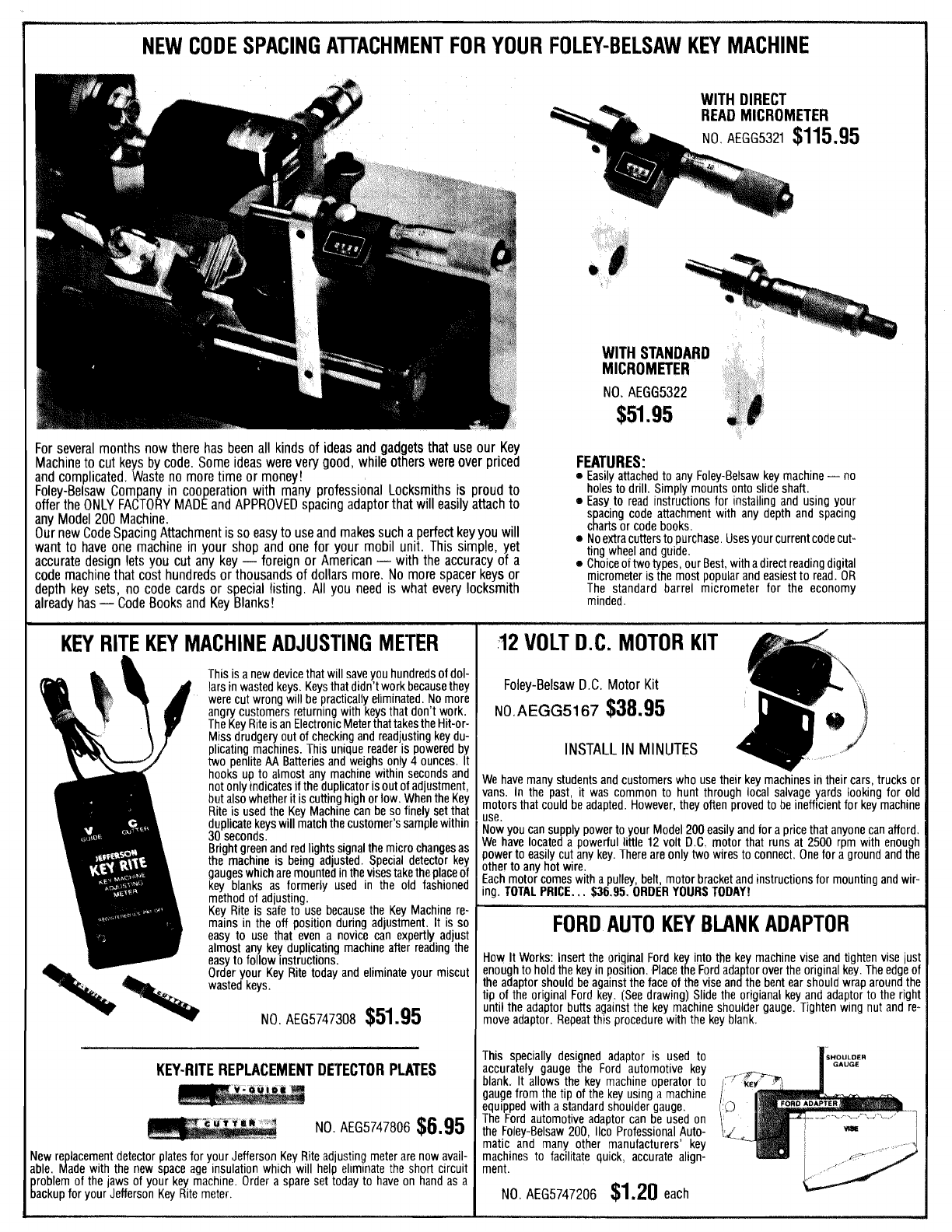
and complicated. Waste no more time or money!
Foley-Belsaw Compan in cooperation with many professional Locksmiths
is
proud to
offer the ONLY FACTO~YMADE and APPROVED spacing adaptorthat will easily attach to
0
Noextracuttersto purchase. Usesyour currentcodecut-
INSTALL IN MINUTES
NO. AEG5747308
$51.95
until the adaptor butts against the key machine shoulder gauge. Tighten wing nut and re-
move adaptor. Repeat this procedure with the key blank.

MODEL
200
KEY
MACHINE
PARTS
LIST
ORDER
NO.
AEG5726003
AEG5726005
AEG57260W
AEG5726007
AEG5726008
AEG5726009
AEG5726013
AEG5726014
AEG5726015
AEG5726016
AEG5726017
AEG5726018
AEG5726019
AEG572600
1
Base
Slide Casting
Clamp
Spring
Tracer Guide (Steel)
Tracer Guide (Duplicating)
Tracer Guide (Code)
Guide Arm Casting
Retainer
Stud
Shaft
Slide Shaft
Pulley (Motor)
Motor
ORDER
NO.
AEG5726029
AEG5726021
AEG5726022
AEG5726023
AEG5726020
AEG572602A
AEG5726002
AEG5726025
AEG5726010
AEG5726012
AEG5726011
AEG5726026
AEG5726027
AEG5726028
Bearing
Wing Nut
Micrometer
Pulley (Cutter Shaft)
Bearing
Alemite Fitting
Belt
Spring
Slotting Cutter
Duplicating Cutter
Code Cutter
Gauge
Motor Mount
Chip Guard
KEY
MACHINE
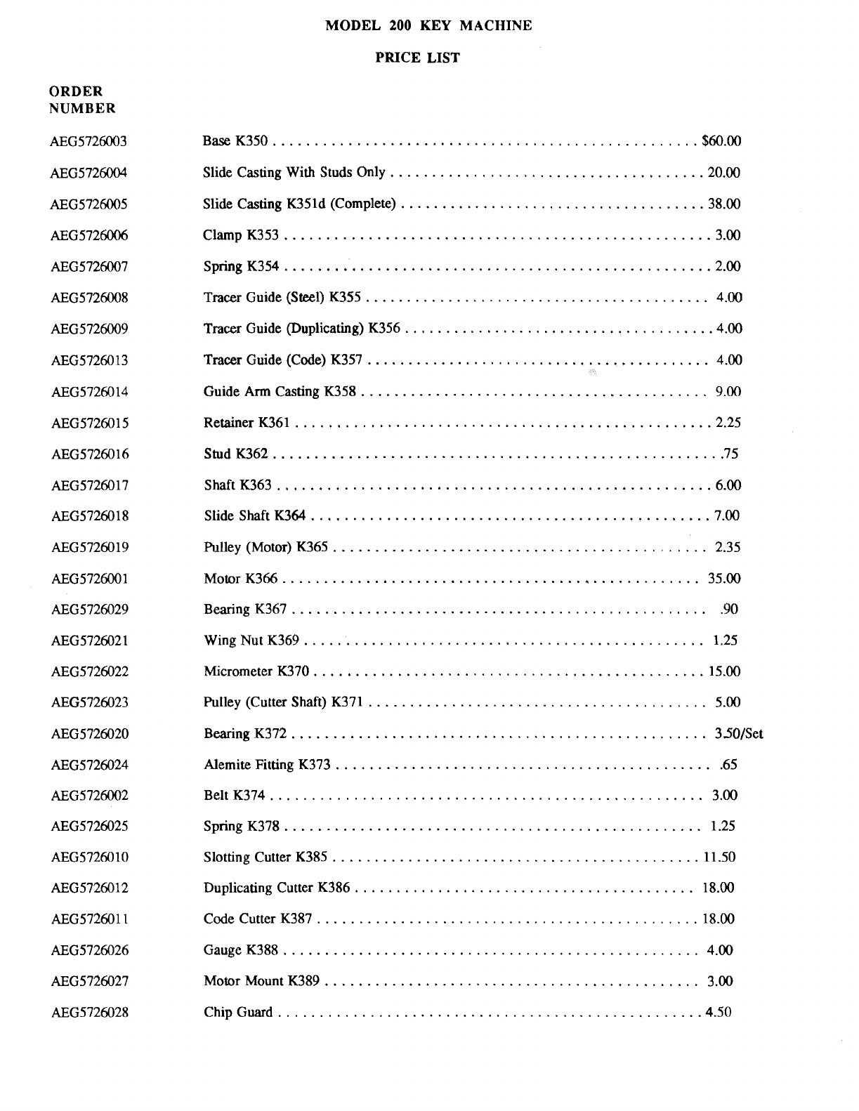
MODEL
200
KEY MACHINE
PRICE LIST
ORDER
NUMBER
BaseK350
...................................................
$60.00
Slide CastingWith Studs Only
.....................................
'20.00
Slide Casting K35ld (Complete)
....................................
.38.00
...................................................
ClampK353 3.00
SpringK354
...................................................
2.00
..........................................
Tracer Guide (Steel) K355 4.00
......................................
Tracer Guide (Duplicating) K356 4.00
Tracer Guide (Code) K357
..........................................
4.00
..........................................
Guide
Arm
Casting K358 9.00
RetainerK361
..................................................
2.25
......................................................
StudK362 75
ShaftK363
....................................................
6.00
SlideShaftK364
................................................
7.00
Rmlley (Motor) K365
.............................................
2.35
MotorK366 .................................................. 35.00
BearingK367 ...................................................90
Wing Nut K369
................................................
1.25
Micrometer K370
...............................................
15.00
.........................................
Pulley (Cutter Shaft) K371 5.00
Bearing K372
..................................................
3501Set
Alemite Fitting K373
..............................................
65
BeltK374
....................................................
3.00
SpringK378
..................................................
1.25
SlottingCutter K385
............................................
11.50
Duplicating Cutter K386
.........................................
18.00
Code Cutter K387
..............................................
18.00
..................................................
GaugeK388 4.00
Motor Mount K389 .............................................3.00
ChipGuard
...................................................
4.50

LOCKSMITHSUPPLIERS
LOCKSMlTH
SUPPLIES
(CANADA)
Agencies W. Pelletier1980, Inc.
651 Motre Dame QuestSte. 375
Montreal, PQ H3C
1H9
Southernlockand Supply Go.
+&It0
EndeavorWay
Pinellas Park, FL33565
Acme Lock and Key
Co.
8020 Olive St.
New Orleans,
LA
70125
Armstrong's Lock
8
Supply, Inc.
1440DutchValley Place. N.E.
Atlanta,
GA
30324
Capitol Lockand Hdwe. Co., Inc.
3730 Georgia Ave., N.W.
Washington, D.C. 20010
Clark Security Products, Inc.
7140 Engineer Rd.
San Diego,
CA
92117
Dire Locksmith Supply Co.
2201 Broadway
Denver, CO 80205
DiversifiedMfg.
8
Marketing
Co., Inc.
P.O. Box 2260
Burlington, NC 27215
Dixie Lock and Key Supplies
2025 N.W.167th St.
Miami, FL 33056
DoorClosers and L.S. Supplies
Pimlico Key Senrice, Inc.
5254 ReisterstownRoad
Baltimore. MD 21215
Doyle Lock
Co.
2211W. River Rd., N.
Minneapolis, MN 5541
1
Dugmoreand Duncan, Inc.
30 Pond Park Rd.
Hingham,
MA
02043
Ewert Wholesale Hardware
4709 W. 120thSt.
Alsip, IL60656
Fairmy Supply, Inc.
2631 Lombardy Lane
Dallas, TX 75220
Foley-BelsawCo.
6301 EquitableRd.
Kansas City, MO 64120
H. Hoffman Co.
7330 W. Montrose Ave.
Chicago, IL60634
IntermountainLock
8
SupplyCo.
3106 S. Main St.
Salt Lake City, UT 84115
Island PacificDistributors, Inc.
1668 King St.
Honolulu, HI 96822
Hans Johnson
Co.
8901 Chancellar Row
Dallas, TX 75247
A.T. Jones and Son
449 W. Congress St.
Detroit, MI48226
(Serving MI Only)
Key HardwareCo.
2400 San Fernando Rd,
Los Angeles, CA 90065
Key Supply
149 Gough St.
San Francisco, CA 94102
M,
Ta lor and Co., Inc.
5645
f
u~ip
st.
Philadelphia, PA 19124 Benton Ltd.J.W.
1271Hornby St,
Vancouver, BC V6A 1
W4
Blander. P.
Locksmith SupplyCo.
28 Mt. RoyalW.
Montreal, PQ
Craig Co. Ltd., C.C.
1500
King Edward St.
Winnipm, MB R3HOR5
HardwareAgencies Ltd.
1220Dundas St,
E.
Toronto. ON
M4M
IS3
.
'The InternationalKey Co.
28 Mount Royal West
Montreal, PQ
Serrubec Inc.
2069 Ave. Chartier
Dorval, PQ H9P 1H3
The
LockwareCo.
1613W. PrattSt.
Baltimore,
MD
21223
Lawrence Locksmith Supply
300Long Beach Rd.
Oceanside, NY 11572
Locks Company
2050 N.E. 151St
Miami, FL 13204
Tweeds Locksmiths, Inc.
601 ElmAve.
Portsmouth,UA 23704
McDonaldLocksmithSupplyCo. Veehoff Supply Co.
P.O. Box 16907 Box 361,908 LakeAve.
Memphis, TN 38116 Storm Lake, IA50588
H.E. Mitchell Co. Wacker Hardware Co.
118 S.E. 8th St. 560
W.
Randolph
Portland. OR 97214 Chicago, IL60606
Mountain West AlanSu
P.O. Box 10780
Pheonix. AZ 85064
Independent Hardware,
I
14 S. Front St.
Ph~ladelphia,PA 19106
Safemasters Co.. Inc.
Shield Su ly
8
Services Ltd.
Unit 17-1!11 St.James St.
Winnipeg, MB R3HOZ1
Judy's Locksmith, Inc.
534 Burlew Dr.
Charleston,W.V. 25302
Stearman Ltd.. Jack
Vancouver, BC V5Y 7L2
Assoc. LS of America, Inc.
3003 Live Oak St.
Dallas, TX 57204
2700 GarfieldAve.
Silver Spring, MO 20910 Locksmith Ledger
850 Busse
Hwy.
M. Shepse Co. Park Ridge, IL60068
1506FifthAvenue 31
2-693-5940
Pittsburgh, PA 15219 NationalLocksmith
K.D.L. Hardware Supply
1621-8th Avenue
Seattle, WA 98101
Kenton LocksmithSupplies, Inc.
10 Lincoln St.
Kansas City, KS 66103
D. Silver Hardware Co., Inc.
I
I
1533 Burgundy Parkway
145 LafayetteAve. Streamwood, IL60107
NorthWhite Plains, NY 10603 31
2-837-2044
MANUFACTURERS
Ideal Security Hardware Gorp.
The
Masler
Sate
Company
45 E. MarylandAve. 1561Grand Bkd.
St. Paul, MN55107 Hamilton, OH 46013
612-488-0202 513-867-4000
Diebld, Inc.
1035 Industrial Parkway
Medina, OH 44256
216-725-0811
All-Lock
P.O. Box 3042
North Brunswick,NJ 08092
201-545-7000
Star Key
8
LockMfg.
1274 FlushingAve.
Brooklyn, NY 11237
21-821-8300
Best Lock Corp.
P.O. Box 50444
Indianapolis. IN46250
317-849-2250
Ilco/Unican Coro. NationalCabinet Lock
Dominion LockCompany, Ltd.
7301 Decarie Blvd.
Montreal, Quebec
CANADAH4P267
514-735-5411
Taylor Lock Company
(See IlcoNnican)
400 Jefferies ~d,
-
P.O.
Box
200
Rockv Mount. NC 27801 Mauldin, SC
29662
919-446-3321 803-297-6655
JunkuncBros./Amer~canLockCo. Norton
Door
Controls
Exchange Rd.
8
Kedtie P.O. Box 25288
Crete, IL 60417 Charlotte, NC 28212
312-534-2000 704-283-2103
VSI HardwareInd.
P.O. Box 4445
Sylmar, CA 91342
213-367-2131
Briggs
8
Stratton
P.O. Box 702
Milwaukee. WI 53201
414-259-5218 ESP Corp.
Enaineered Securih, Products
373 HarvardSt.
.
Leominster, MA 01453
617-534-6121
Weiser Lock
5555 McFaddenAve.
Chicago Lock Company
4311W. Belmont Ave.
Chicago. lL60641
312-282-7177
Kwikset Sargent
&
Company
516 E. Santa Ana St. 100 Sargent Drive
Anaheim, CA 92805 New Haven. CT 06509
714-535-8111 203-562-2151
Huntington Beach, CA 92649
714-898-081
1
Fort Lock Corp.
3000 N. River Rd. Weslock Company
13344 S. Main Street
Los Angeles, CA 90061
213-327-2770
Lab Secur~tySystemsCorp. SargentY Greenleaf, Inc.
P.O. Box
54
1 Sercurity Drive
Terlyville. CT 06786 Nicholasville,
KY
40356
203-5896037 606-885-941
1
Corbin Cabinet Lock
225 EpiscopalRd.
Berlin, CT 06037
203-255-241
1
River Grove, IL 60171
312-456-1100
Gil-Ray Tool
1306 McGrawStreet
Box 801
Bay City, MI48706
517-892-6870
Wright Prod., Inc.
2515 Wabash
St. Paul,MN 55114
612-642-2800
Lori Corp. Schlage LockCompany
Old Turnp~ke P.O.
Box
3324
Southington, CT 06786 San Francisco, CA 94119
203-621-3601 415-467-1
100
Corkey ControlSystems, Inc.
207050 S. Western Ave. $108
Torrance, CA 90501
213-533-1425 Yale Security Prod.
P.O. Box 25288
Charlotte, NC 28212
740-283-2101
Lucky Line Prod Scotsman Securily Prod., Inc.
P0. Box 17397 P.O. Box 1250
San Diego, CA 92117 Pine Grove, CA $5665
619-270-0153 209-295-5498
Curtis Industries,Inc.
34999 Curtis Blvd.
Eastlake,
OH
44094
216-951-2400
H.PC., Inc.
3999 N. 25th Ave.
Schiller Park, IL60176
312-671-6280
Dexter Locks
Sub. of Master Lock
300 Webster Rd.
Auburn, AL 36830
205-826-330
Master Lock Company Simplex Access Controls, Corp
2600 North
32nd
St. 2941 lrldiana A*.
Milwaukee,WI 53210 Winston Salem, NC 27115
414-444-2800 919-725-1331
Harloc Product CorD.
135 Wood Street
West Haven, CT 06516
203-934-2683
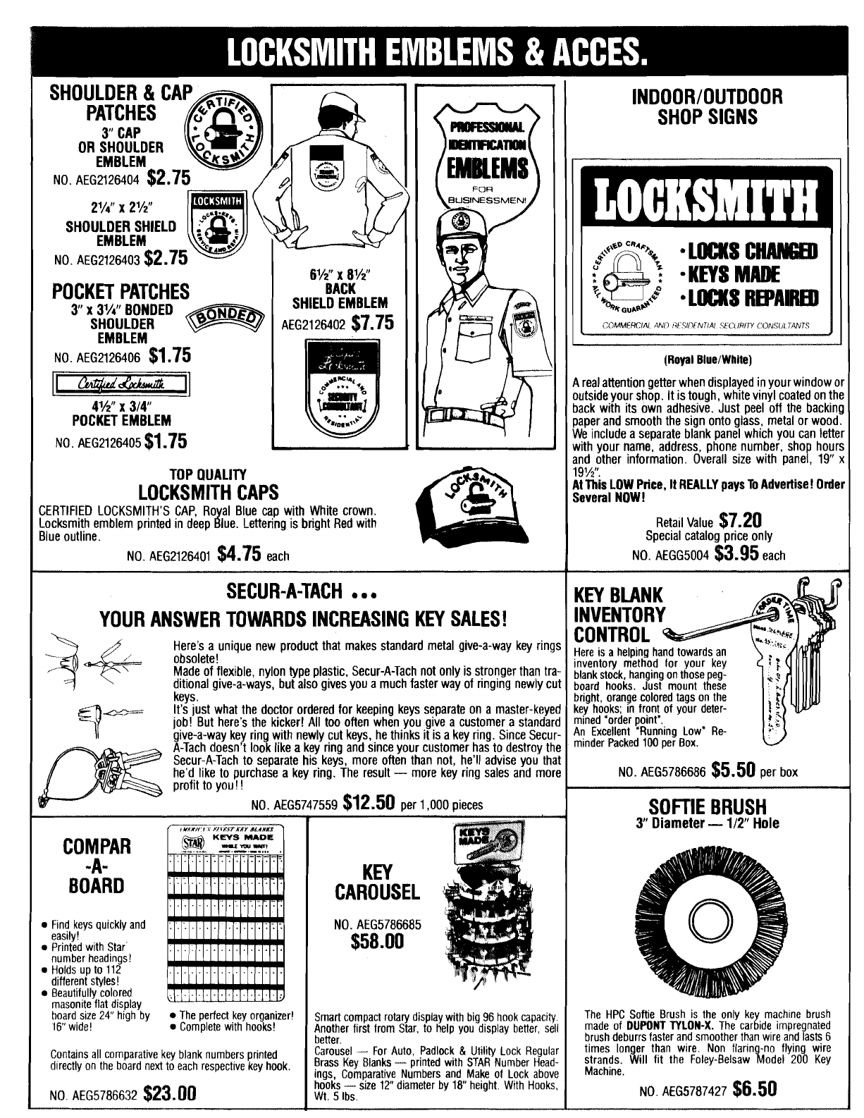
POCKET PATCHES
3
x
3'/4"
BONDED
(Royal
BluetWhite)
realattention getterwhen displayedinyourwindow or
utsideyour shop. Itistough, white vinyl coated onthe
back with its own adhesive. Just peel off the backing
TOP
QUALITY
LOCKSMITH CAPS
YOUR ANSWER TOWARDS INCREASING KEY SALES!
ditional give-a-ways, but also givesyou a much faster way of ringing newlycut
SOFTIE BRUSH
3
Diameter
-
112"
Hole
Find keys
quickly
and

MODEL
200
KEY MACHINE INSTALLATION
ADJUSTMENT AND OPERATION
FOR
DUPLICATING CYLINDER KEYS
The key machine is the locksmith's primary tool and one of his best sources of income. The basic function
of a key machine is to duplicate keys accurately. It is a delicate piece of equipment and requires the
maintenance and care of a precision machine. It should be use
for general shop use. Once your key machine is set main that way if you
do not abuse it by misuse.
A
good key machine curately duplicate a
key to within one or two thousandths of an inch. This properly duplicate keys
that
will
work.
A
locksmith takes great pride in up for accurate duplication.
Many key machines in use today do not duplicate t adjusted or operated
properly. You have no doubt heard the complai
dime stores, or grocery stores, that the key did not wor
because of the quality of the key machine but d
in
settingthe machine in proper adjustment and keeping it that
way.
Your FOLEY-BELSAW Model
200
Key Machine has been designed with precision, accuracyand versatility
in mind. Specialfeatures have been incorporated into the design to make it a combination key duplicating
machine and a code cutting machine. These instructions
will
dealwith the installation and operation of the
machine for duplicating cylinder keys. Cuttingkeys by codeand cuttingflat steelkeyswill also be covered.
The location of your key machine is
very
important. Itshould be set up in a place in your shop that offers
natural light if at all possible.
A
bench tool light should also be used. You should have enough work area to
allow for a key display board to be hung on the wall beside or behind the machine for easy accessibility.
KEY
MACHINE
Page
1
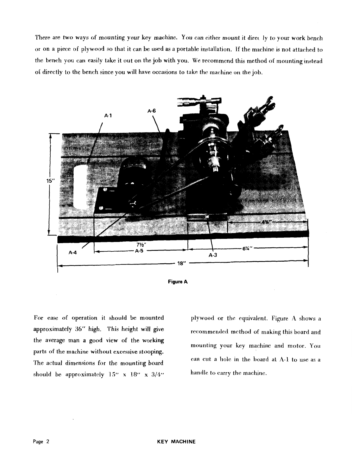
There
are
two ways of mounting your key machine. You can elther mount it direc ly
to
your work bench
or
on a piece of plywood
so
that it can
be
used as a portable installation.
If
the machine is not attached to
the
bench you can easily take it out on the job with
yea.
We rerommcnd this method
of
mounting instead
of directly
to
the bench since you
will
have occasions totake the machine or1 the job.
Figure
A
For ease of operation
it
should be mounted plywood or the equivalent.
Figure
i.1
shows
a
approximately
36"
high. This height
will
give recornmenJed method of making this hoard
and
the average man a good view of the working mounting your key machirle
ar~d
motor.
Yo11
parts of the machine without excessive stooping. can cut
il
hole in the board at
A-1
to
rise
as a
'I'he actual dimensions for
the
mounting board
should
he
approximately
15"
x
18"
x
3/411
handle
to
carry the machine.
KEY
MACHINE

shown in Figure
A.
Line up the front edge so be seton the shaft with the set screw toward the
that it is square with the mounting board. The motor and flush with the end of the motor shaft
front edge should be approximately
4%"
back as shown at
A-4.
Then attach the motor mount
from the frontedge of the board as shown. to the motor, with screws provided in the motor.
Line up the motor so that the belt
A-6,
will
run
straight between the motor and machine pulley.
Line up the side edges of the machine so there In the diagram shown above, at position
A-5,
is an equal distance on each side of the board. the distance from the back of the Key Machine
Use the mounting holes on the base of the base, to the back of the motor mount,
is
ap
machine as shown at
A-3
to mark the board for poximately
7%
inches. Next mark the holes in
the mounting screws which you will find in your the motor mount and using the screws you re-
parts bag. Tighten these screws down tight so ceived in the parts bag, fasten the motor to the
the machine
is
solid. Next unpack the motor mounting board. Install the drive belt,
A-6.
Cut
out hole
A-1
for handle.
KEY
MACHINE
Page
3
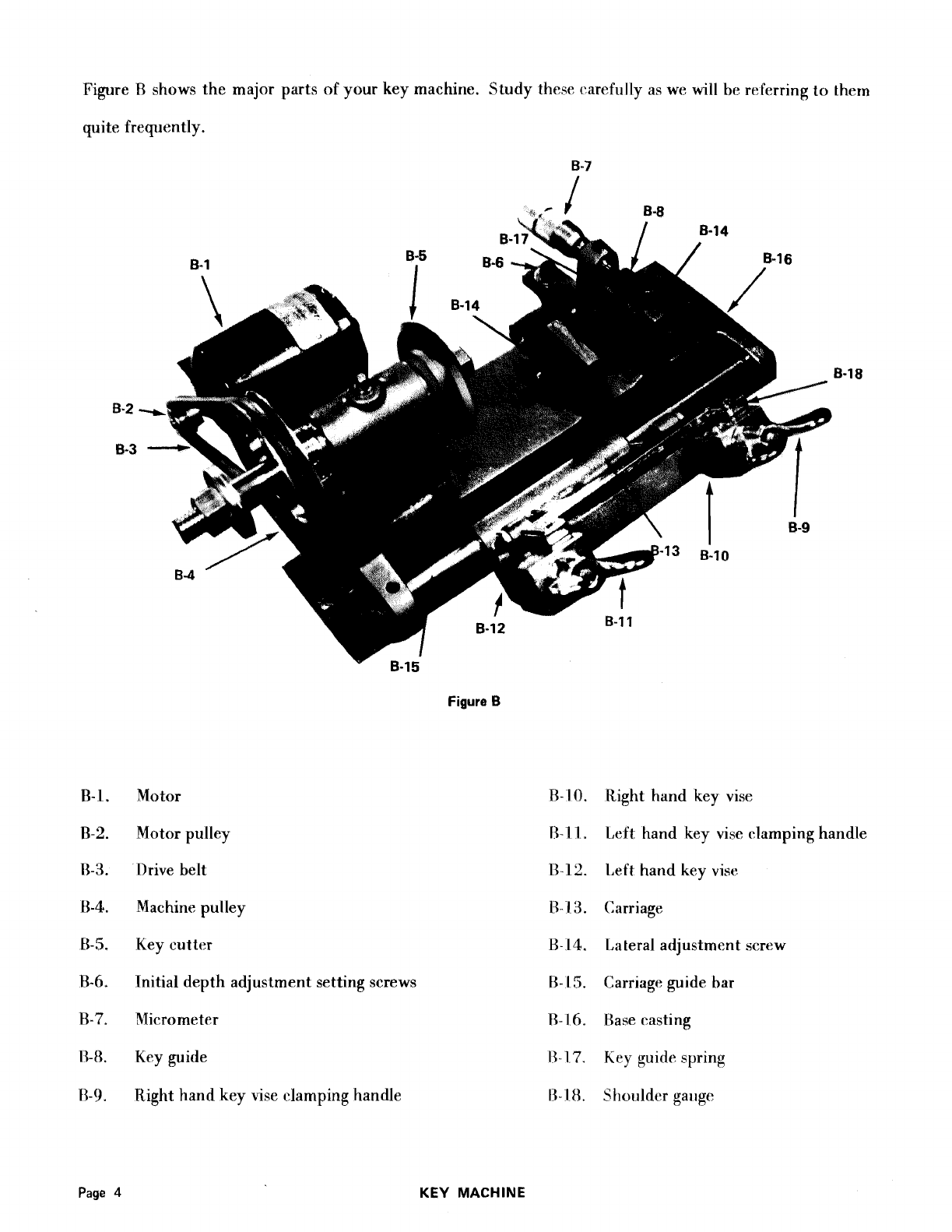
Figure
R
shows the major parts of your key machine. Study these carefully as we will be referring to thern
quite frequently.
B-7
Figure
B
Motor
Motor pulley
Drive belt
Machine pulley
Key cutter
Initial depth adjustment setting screws
Micrometer
Key guide
Right hand key vise clamping handle
Right hand key vise
1,eft hand key vise clamping handle
l,eft hartd key vise
Carriage
Lateral adjustment screw
Carriage guide bar
Base casting
Key
guide spring
Slioi~ldcrgallge
KEY
MACHINE
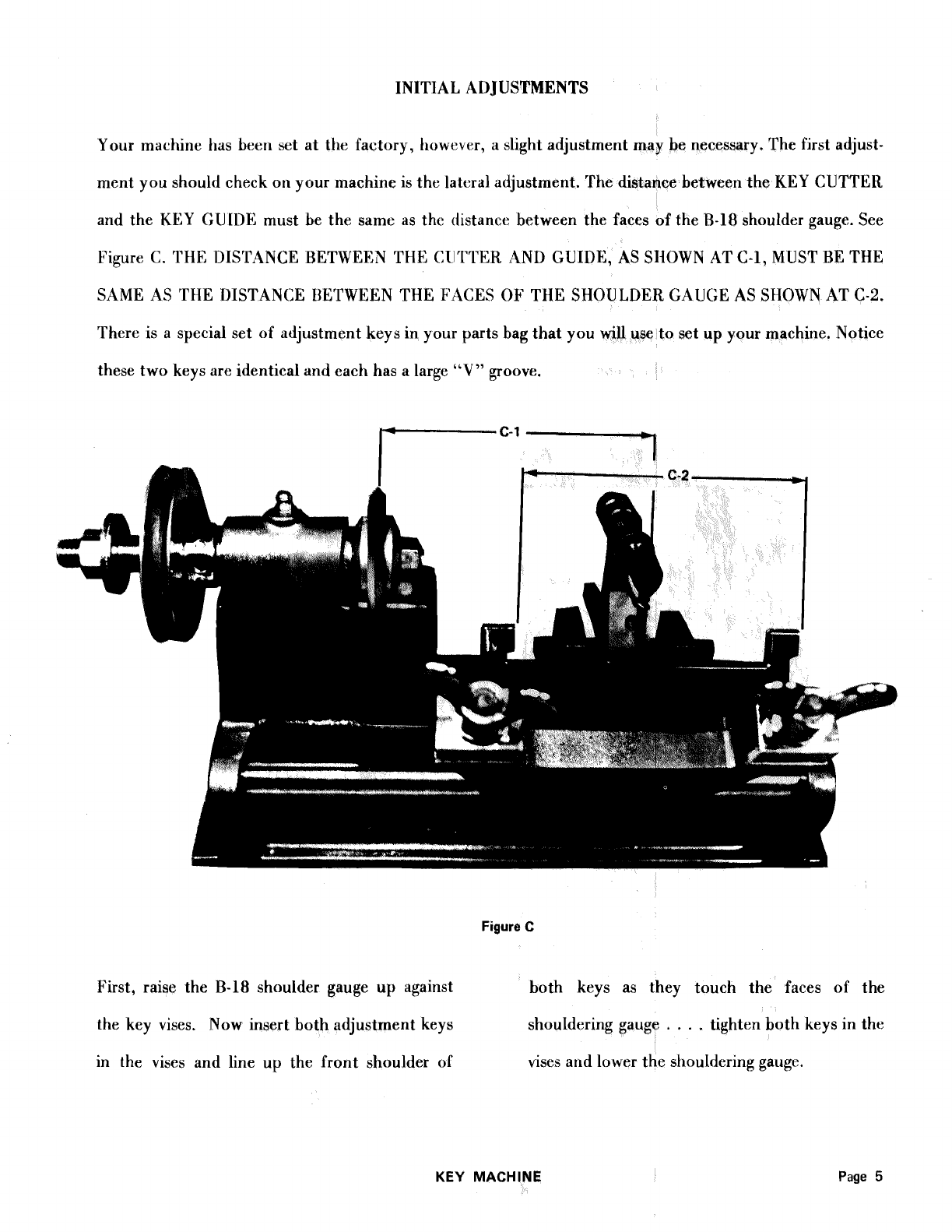
INITIAL AT) JUSTMENTS
Your machine has been set at the factory, however, a slight adjustment may be necessary. The first adjust-
ment you should check on your machine is the latc-raladjustment. The distance between the KEY CUTTER
and the KEY GUIDE must be the same as the distance between the faces of the
€3-18
shoulder gauge. See
Figure
C.
THE DISTANCE RETWEEN THE
CII'TTEK.
AND GUIDE, AS SHOWN AT C-1, MUST RE THE
SAME AS THE DISTANCE BETWEEN THE
FACES
OF THE SHOULDER GAUGE AS SHOWN AT C-2.
There is
a
special set of adjustment keysin your parts bag that you
HriU
use
to
set
up
your machine. Notice
these two keys are identical and each has a large
"V"
groove.
Figure
C
First, raise the
B-18
shoulder gauge
up
against both keys as they touch the faces of the
the key vises. Now insert both adjustment keys shouldering gauge
.
.
.
.
tighten both keys in the
in the vises and line up the front shoulder of vises and lower the shouldering gauge.
KEY
MACHINE
Page
5
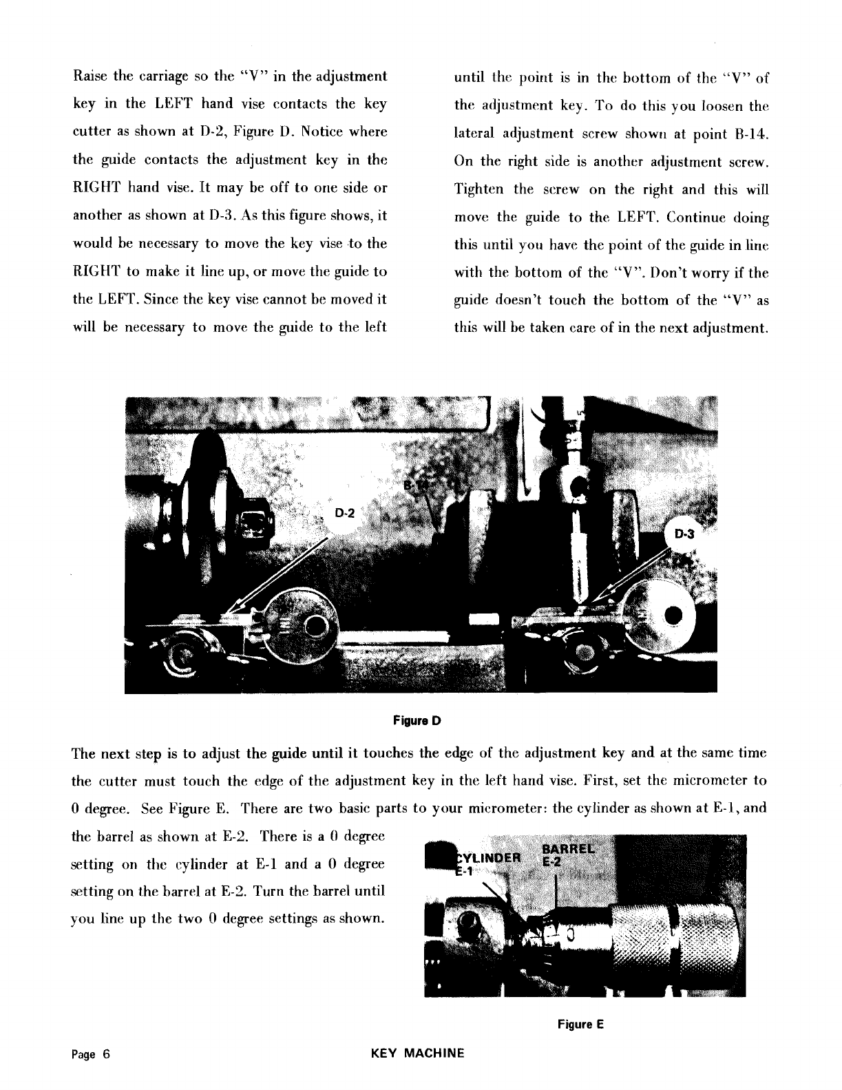
Raise the carriage so the
"V"
in the adjustment
key in the
LEFT
hand vise contacts the key
cutter as shown at
11-2,
Figure
I).
Notice where
the guide contacts the adjustment key in the
RIGHT hand vise. It may be off to one side or
another as shown at
11-3.
As this figure shows, it
would be necessary to move the key vise to the
RIGHT to make it line up, or move tht: guide to
the
LEFT.
Since the key vise cannot be moved it
will be necessary to move the guide to the left
until
the
point is in the bottom of
the
"V"
of
the adjustment key.
To
do
this you loosen the
lateral adjustment screw showti at point
W-14.
On the right side is another adjustment screw,
Tighten the screw on the right and this will
move the guide to the
L,EFfI'.
Continue doing
this until you have the point of the guide in line
with the bottom of the
"V".
Don't worry if the
guide doesn't touch the bottom of the
"V"
as
this will be taken care of in the next adjustment.
Figure
D
The next step is to adjust the guide until it touches the edge of the adjustment key and at the same time
the cutter must touch the edge of the adjustment key in the left hand vise. First, set the micrometer to
0
degree. See Figure
E.
There are two basic parts to your micrometer: the cylinder as shown at
E-1,
and
the barrel as shown at
E-2.
There is a
0
degree
setting
on
the cylinder at
E-l
and a
0
degree
setting on t.hebarrel at
E-2.
Turn the barrel until
you line up the two
0
degree settings as shown.
Figure
E
KEY
MACHINE
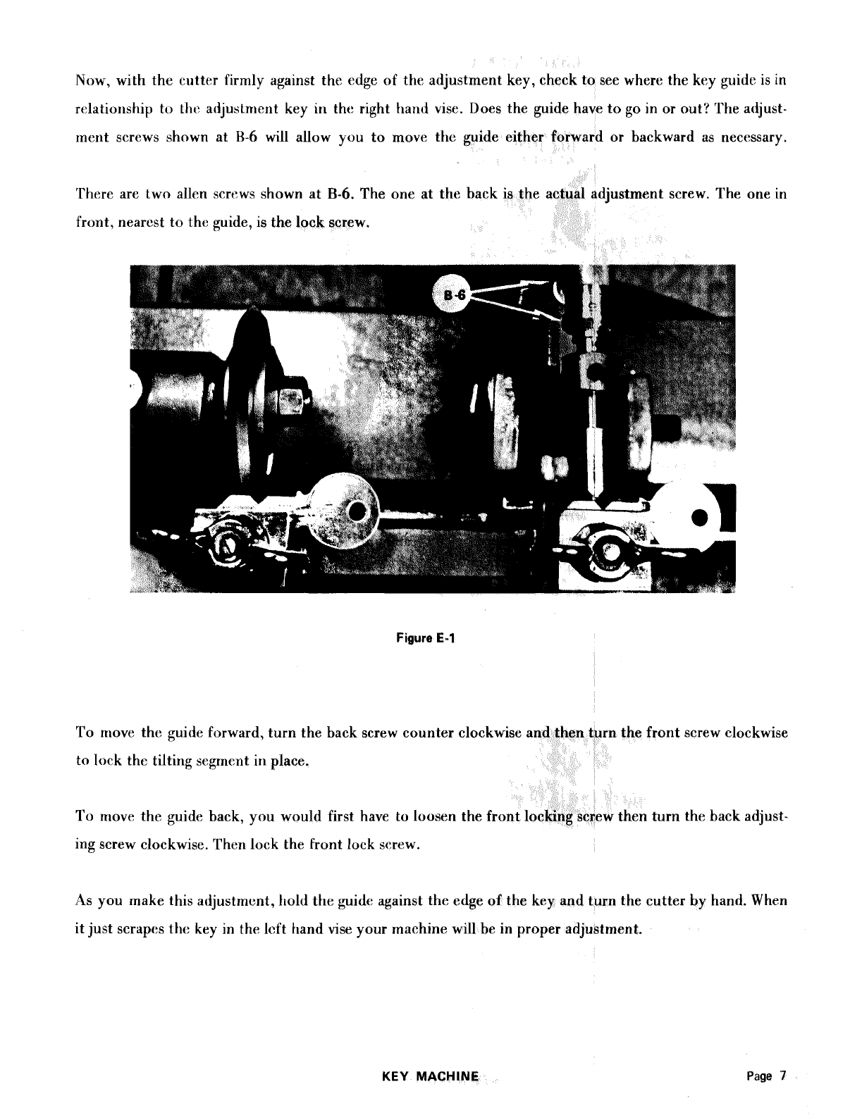
]Vow,
with the cutter firmly against the edge of the adjustment key, check to see where the key guide is in
relationship
tu
thc adjustment key in tht: right
hand
vise. Does the guide have togo in or out? The atijust-
rnerit screws shown at
H-6
will allow you to move the guide either forward or backward as necessary.
There are two allen screws shown at
B-6.
The one at the djustment screw. The one in
front, nearest tothe guide, is the lock screw.
Figure
E-1
To move the guide forward, turn the back screw counter clockwise n thefront screw clockwise
to lock the tilting segrnent in place.
To move the guide back, you would first have to loosen the fro turn the back adjust-
ing screw clockwise. Then lock the front lock screw.
As you rnake this acijustmcnt, hold the guide against the edge of the key and turn the cutter by hand. When
itjust scrapes the key in the lcft hand vise your machine will be in proper adjustment.
KEY
MACHINE
Page
7

1,UHRICATION AND CUTTER ROTATION
LIGHT
OIL
ON
MICROMETER
Figure
E-2
Use a light
#10
motor oil for-the
B-1
S
carriage machine clear of metal chips and shav
guide bar, use medium gun grease on the key times. The main shaft carrying the
machine cutter shaft. Oil the carriage guide bar factory lubricated and needs only
as needed to insure ease of operation. Be sure amount of gun grease once a year.
7
to keep this guide bar and the rest of the does not require
ANY
lubrication.
ings
cul
a
'he
I
at all
:ter is
small
motor
Figure
F
The cutter rotation is very important. The file type cutter was installed on your machine at the factory
and the teeth should he pointing DOWN. A11 cutters have teeth pointing in the same direction. AI,WAYS
install the cutters as shown in Figure
F
with the teeth pointing DOWN. lnstallatiori of a cutter with the
teeth pointing
11P
would make the cutter work in the wrong direction and damage it. The rotation of your
motor is so that the cutter revolves in the direction of Figure
I?.
This
throws the chips and shavings down
and away from your face.
Page
8
KEY
MACHINE

CODE
CUTTER
There are three types of cutters used onyour machine. Th
type file cutter was installed at the factory. 'This cutter i
cylinder keys only. This
"V"
type file cutter can be
both duplicating and cutting keys by code. The other file
in the parts hag is the one you will be using most of the time.
It is primarily for duplicating cylinder keys.
Steel
keys should
NOT be cut with these cutters. The third cutter in the parts bag
is used for cutting steel keys.
STEEL
CUTTER
Since most of your cutting on the key machine will be duplicating keys, we'll change over tothe duplicat-
ing cutter. You
will
be
using the
"V"
type cutter rnore
fo
ing cylinder keys.
In your parts bag you
will
find a file type dup
are made with the same angle
as
the cutter.
DUPLICATING STEEL
GUIDE GUIDE
CODE
GUIDE
KEY MACHINE
Page
9
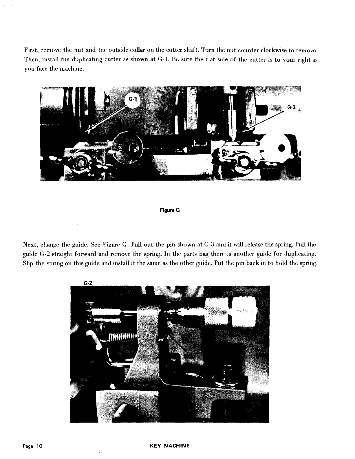
First, rrnlove the nut and tho outsido collar on the cutter shaft. l'urn the nut counter-clockwise to removo.
Then, install the duplicating cutter as shown at
G-1.
Be sure the flat side of the clatter is to your right as
you
Eacc
the machine.
Figure
G
Next, change the guide. See Figure
G.
Pull out the pin shown at
G-3
and it will release the spring. Pull the
guide
G-2
straight forward
and
rernove the spring. In the parts
bag
there is another guide for duplicating.
Slip thc spring on this guide
and
install it the sarne as the other guide. Put the pin back in to
hold
the spring.
Page
10
KEY
MACHINE
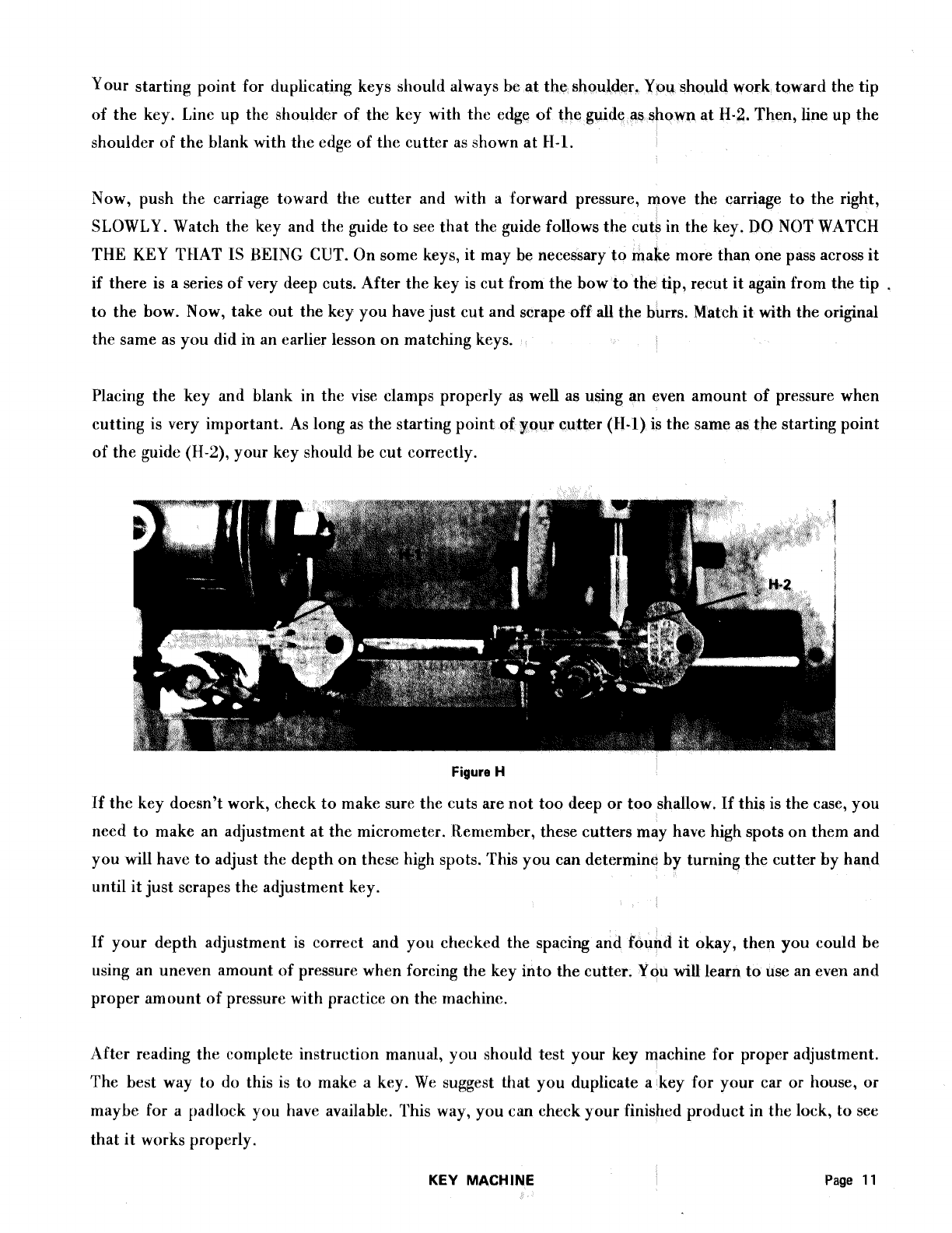
Your starting point for duplicating keys should always be at the shoulder, You should work toward the tip
of the key. Line up the shoulder of the key with the edge of the guide as shown at
H-2.
Then, line up the
shoulder of the blank with the edge of the cutter as shown at 11-1.
Now, push the carriage toward the cutter and with
a
forward pressure, move the carriage to the right,
SLOWLY. Watch the key and the guide to see that the guide follows the cuts in the key.
DO
NOT WATCH
THE KEY TI-IAT IS BEING CUT. On some keys, it may be necessary to make more than one pass across it
if there is a series of very deep cuts. After the key is cut from the bow tothe tip, recut it again from the tip
,
to the bow. Now, take out the key you have just cut and scrape off
all
the burrs. Match it with the original
the same as you did in an earlier lesson on matching keys.
Placing the key and blank in the vise clamps properly as well as using an even amount of pressure when
cutting is very irnportant. As long as the starting point of your cutter (11-1) is the same as the starting point
of the guide
(H-2),
your key should he cut correctly.
-
-
-
-
-
--
-
Figure
H
If the key doesn't work, check tomake sure the cuts arenot too deep or too shallow. If this is the case, you
need to make an adjustment at the micrometer. Remember, these cutters may have high spots on them and
you will have to adjust the depth on these high spots. 'I'his you can determine by turning the cutter by hand
until itjust scrapes the adjustment key.
If your depth adjustment is correct and you checked the spacing and found
it
okay, then you could be
using an uneven amount of pressure when forcing the key into the cutter. You will learn touse an even and
proper amount of pressure with practice on the machine.
After reading the complete instruction manual,
you
should test your key machine for proper adjustment.
The best way
to
do
this is to make
a
key. We suggest that you duplicate a key for your car or house, or
maybe for a patllock you have available. This way, you can check your finished product in the lock, to see
that it works propcrly.
KEY
MACHINE
Page
11
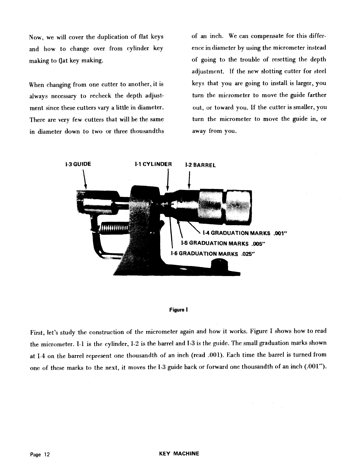
Now, we
will
cover the duplication of flat keys
and how to change over from cylinder key
making toQat key making.
When changing from one cutter to another, it is
always necessary to recheck the depth adjust-
ment since these cuttersvary a little in diameter.
There are very few cutters that will be the same
in diameter down to two or three thousandths
of
an
inch. We can compensate for this differ-
ence
in
diameter hy using the micrometer instead
of going to the trouble of resetting the depth
adjustment. [f the new slotting cutter for steel
keys that you are going to instdl is larger, you
turn the micrometer to move the guide farther
out, or toward you.
If
the cutter is smaller, you
turn the micrometer to move the guide in, or
away from you.
1-3
GUIDE
1-1
CYLINDER
1-2
BARREL
\
1-5
GRADUATIONMARKS
.W5
1-6
GRADUATIONMARKS
,025"
Figure
I
First, let's study the construction of the micrometer again and how it works. Figure
I
shows how toread
the micrometer.
1-1
is the cylinder,
1-2
is the barrel and
1-3
is the guide. The small graduation marks shown
at
1-4
on the barrel represent one thousandth of an inch (read .001). Each time the barrel is turned from
one of these marks to the next, it moves the
1-3
guide back or Forward one thousandth of an inch (.001").
Page
12
KEY MACHINE

1-3
GUIDE
1-1
CYLINDER
1-2
BARREL
-5
GRADUATION MARKS
.00W
There are
25
of these graduation marks around the barrel wh -five thousandthsof an
inch
(.025").
If
you turn the barrel one complete circle, ould move the
1-3
guide
.025**.
The second
graduation marks on the barrel are shawn
at
1-5.
The epresent five thousandths of
an
inch
(.005").
By turning the barrel from one mar
0
degree to
5
would move
the guide
.005".
All
you have toremember for the barrel graduation
marks
is
that the short ones represent
-001"
and the long onesrepresent
.005"
and one complete circle represents
.025".
To make these decimals
clear in your mind, the following shows the decimal equivalent of the inch and how toread it:
.001"
..........
One thousandths of an inch
.005"
..........
Five thousandths
.025"
..........
Twenty-five thousandths
.05Ou
..........
Fifty thousandths
.075"
..........
Seventy-five thousandths
.100"
..........
One hundred thousandths
..........
.125"
One hundred and twenty-five thousandths
.150"
..........
One hundred and fifty thousandths
.175"
..........
One hundred and seventy-fivethousandths
.200"
..........
Two hundred thousandths
KEY MACHINE
Page
13
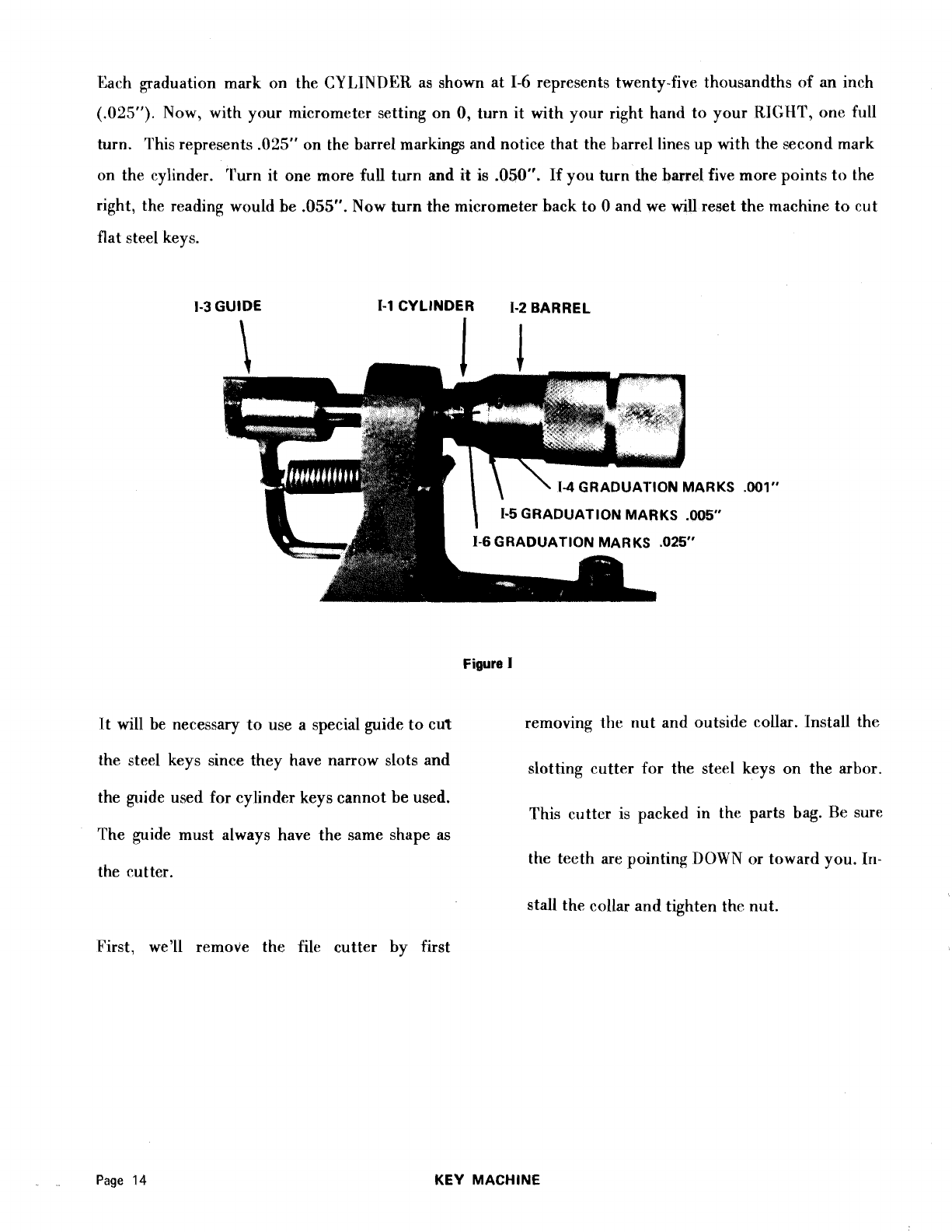
Rach graduation mark on the
CY1,INI)E:R
as shown at
1-6
represents twenty-five thousandths of an inch
(-025").
Now, with your micrometer setting on
0,
turn it with your right hard to your
RIGHT,
one f~ll
turn. This represents
.025"
on the barrel markings and notice that the barrel lines up with the second mark
on the cylinder. Turn it one more full turn and
it
is
.050".
If you turn the barrel five more points to the
right, the reading would be
.055".
Now turn the micrometer back to
0
and we will reset the machine to cut
flat steel keys.
1-3
GUIDE
1-1
CYLINDER 1-2 BARREL
-5GRADUATIONMARKS .005"
-6
GRADUATION MARKS .025"
Figure
I
It will be necessary to use a special guide tocut removing the nut and outside collar. Install the
the steel keys since they have narrow slots and slotting cutter for the steel keys on the arbor.
the guide used for cylinder keys cannot be used. This cuttcr is packed
in
the parts bag. Re sure
The guide must always have the same shape
as
the teeth are pointing
DOWN
or toward you.
111-
the cutter.
stall the collar and tighten the nut.
First, we'll remove the file cutter by first
Page
14
KEY MACHINE
Other manuals for 200
1
Popular Tools manuals by other brands


U-Line
U-Line H-3402 quick start guide

Rose electronics
Rose electronics ALL2GETHER owner's manual

MSW Motor Technics
MSW Motor Technics MSW-PTM-01 user manual

Berner
Berner X-Lux Wireless instruction manual

Max
Max TA551A/16-11 CE Operating and maintenance manual

Roller
Roller ROLLER'S King 1 instruction manual